check engine light ALFA ROMEO STELVIO 2021 User Guide
[x] Cancel search | Manufacturer: ALFA ROMEO, Model Year: 2021, Model line: STELVIO, Model: ALFA ROMEO STELVIO 2021Pages: 280, PDF Size: 10.02 MB
Page 82 of 280
GETTING TO KNOW YOUR INSTRUMENT PANEL
80
the oil level can be checked on the display
upon entering the vehicle and also by acti-
vating the “Oil level” function on the Informa -
tion and Entertainment System.
Contact an authorized dealer as soon as
possible.
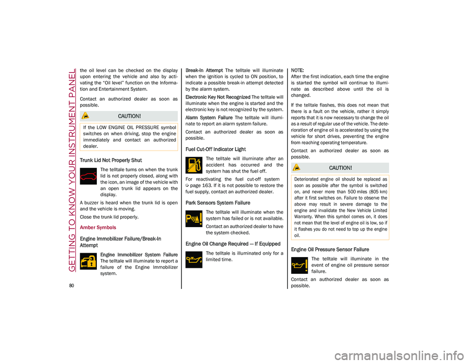
Trunk Lid Not Properly Shut
The telltale turns on when the trunk
lid is not properly closed, along with
the icon, an image of the vehicle with
an open trunk lid appears on the
display.
A buzzer is heard when the trunk lid is open
and the vehicle is moving.
Close the trunk lid properly.
Amber Symbols
Engine Immobilizer Failure/Break-In
Attempt
Engine Immobilizer System Failure
The telltale will illuminate to report a
failure of the Engine Immobilizer
system. Break-In Attempt
The telltale will illuminate
when the ignition is cycled to ON position, to
indicate a possible break-in attempt detected
by the alarm system.
Electronic Key Not Recognized The telltale will
illuminate when the engine is started and the
electronic key is not recognized by the system.
Alarm System Failure The telltale will illumi -
nate to report an alarm system failure.
Contact an authorized dealer as soon as
possible.
Fuel Cut-Off Indicator Light
The telltale will illuminate after an
accident has occurred and the
system has shut the fuel off.
For reactivating the fuel cut-off system
Ú
page 163. If it is not possible to restore the
fuel supply, contact an authorized dealer.
Park Sensors System Failure
The telltale will illuminate when the
system has failed or is not available.
Contact an authorized dealer to have
the system checked.
Engine Oil Change Required — If Equipped
The telltale is illuminated only for a
limited time.
NOTE:
After the first indication, each time the engine
is started the symbol will continue to illumi
-
nate as described above until the oil is
changed.
If the telltale flashes, this does not mean that
there is a fault on the vehicle, rather it simply
reports that it is now necessary to change the oil
as a result of regular use of the vehicle. The dete -
rioration of engine oil is accelerated by using the
vehicle for short drives, preventing the engine
from reaching operating temperature.
Contact an authorized dealer as soon as
possible.Engine Oil Pressure Sensor Failure
The telltale will illuminate in the
event of engine oil pressure sensor
failure.
Contact an authorized dealer as soon as
possible.
CAUTION!
If the LOW ENGINE OIL PRESSURE symbol
switches on when driving, stop the engine
immediately and contact an authorized
dealer.
CAUTION!
Deteriorated engine oil should be replaced as
soon as possible after the symbol is switched
on, and never more than 500 miles (805 km)
after it first switches on. Failure to observe the
above may result in severe damage to the
engine and invalidate the New Vehicle Limited
Warranty. When this symbol comes on, it does
not mean that the level of engine oil is low, so if
it flashes you do not need to top up the engine
oil.
21_GU_OM_EN_USC_t.book Page 80
Page 84 of 280
GETTING TO KNOW YOUR INSTRUMENT PANEL
82
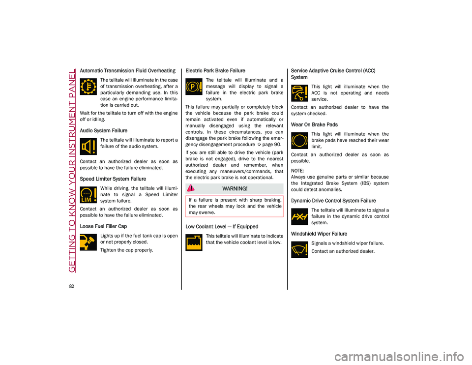
Automatic Transmission Fluid Overheating
The telltale will illuminate in the case
of transmission overheating, after a
particularly demanding use. In this
case an engine performance limita-
tion is carried out.
Wait for the telltale to turn off with the engine
off or idling.
Audio System Failure
The telltale will illuminate to report a
failure of the audio system.
Contact an authorized dealer as soon as
possible to have the failure eliminated.
Speed Limiter System Failure
While driving, the telltale will illumi -
nate to signal a Speed Limiter
system failure.
Contact an authorized dealer as soon as
possible to have the failure eliminated.
Loose Fuel Filler Cap
Lights up if the fuel tank cap is open
or not properly closed.
Tighten the cap properly.
Electric Park Brake Failure
The telltale will illuminate and a
message will display to signal a
failure in the electric park brake
system.
This failure may partially or completely block
the vehicle because the park brake could
remain activated even if automatically or
manually disengaged using the relevant
controls. In these circumstances, you can
disengage the park brake following the emer -
gency disengagement procedure
Ú
page 90.
If you are still able to drive the vehicle (park
brake is not engaged), drive to the nearest
authorized dealer and remember, when
executing any maneuvers/commands, that
the electric park brake is not operational.
Low Coolant Level — If Equipped
This telltale will illuminate to indicate
that the vehicle coolant level is low.
Service Adaptive Cruise Control (ACC)
System
This light will illuminate when the
ACC is not operating and needs
service.
Contact an authorized dealer to have the
system checked.
Wear On Brake Pads
This light will illuminate when the
brake pads have reached their wear
limit.
Contact an authorized dealer as soon as
possible.
NOTE:
Always use genuine parts or similar because
the Integrated Brake System (IBS) system
could detect anomalies.
Dynamic Drive Control System Failure
The telltale will illuminate to signal a
failure in the dynamic drive control
system.
Windshield Wiper Failure
Signals a windshield wiper failure.
Contact an authorized dealer.
WARNING!
If a failure is present with sharp braking,
the rear wheels may lock and the vehicle
may swerve.
21_GU_OM_EN_USC_t.book Page 82
Page 86 of 280
GETTING TO KNOW YOUR INSTRUMENT PANEL
84
Green Symbols
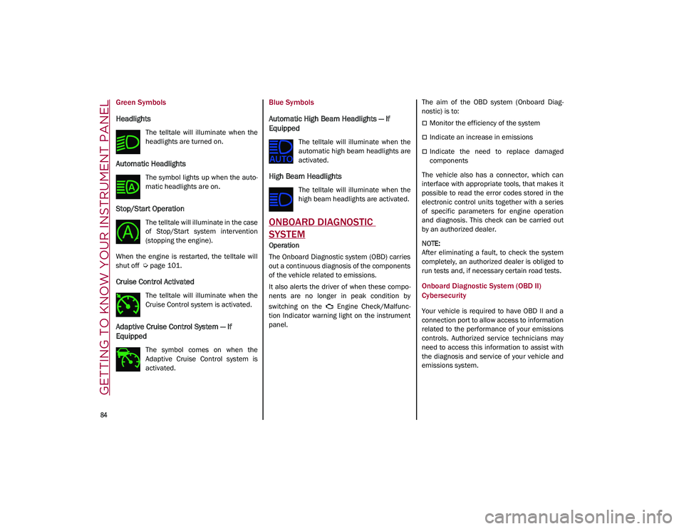
Headlights
The telltale will illuminate when the
headlights are turned on.
Automatic Headlights
The symbol lights up when the auto-
matic headlights are on.
Stop/Start Operation
The telltale will illuminate in the case
of Stop/Start system intervention
(stopping the engine).
When the engine is restarted, the telltale will
shut off
Ú
page 101.
Cruise Control Activated
The telltale will illuminate when the
Cruise Control system is activated.
Adaptive Cruise Control System — If
Equipped
The symbol comes on when the
Adaptive Cruise Control system is
activated.
Blue Symbols
Automatic High Beam Headlights — If
Equipped
The telltale will illuminate when the
automatic high beam headlights are
activated.
High Beam Headlights
The telltale will illuminate when the
high beam headlights are activated.
ONBOARD DIAGNOSTIC
SYSTEM
Operation
The Onboard Diagnostic system (OBD) carries
out a continuous diagnosis of the components
of the vehicle related to emissions.
It also alerts the driver of when these compo -
nents are no longer in peak condition by
switching on the Engine Check/Malfunc -
tion Indicator warning light on the instrument
panel. The aim of the OBD system (Onboard Diag
-
nostic) is to:
Monitor the efficiency of the system
Indicate an increase in emissions
Indicate the need to replace damaged
components
The vehicle also has a connector, which can
interface with appropriate tools, that makes it
possible to read the error codes stored in the
electronic control units together with a series
of specific parameters for engine operation
and diagnosis. This check can be carried out
by an authorized dealer.
NOTE:
After eliminating a fault, to check the system
completely, an authorized dealer is obliged to
run tests and, if necessary certain road tests.
Onboard Diagnostic System (OBD II)
Cybersecurity
Your vehicle is required to have OBD II and a
connection port to allow access to information
related to the performance of your emissions
controls. Authorized service technicians may
need to access this information to assist with
the diagnosis and service of your vehicle and
emissions system.
21_GU_OM_EN_USC_t.book Page 84
Page 87 of 280
85
EMISSIONS INSPECTION AND
MAINTENANCE PROGRAM
In some localities, it may be a legal require-
ment to pass an inspection of your vehicle's
emissions control system. Failure to pass
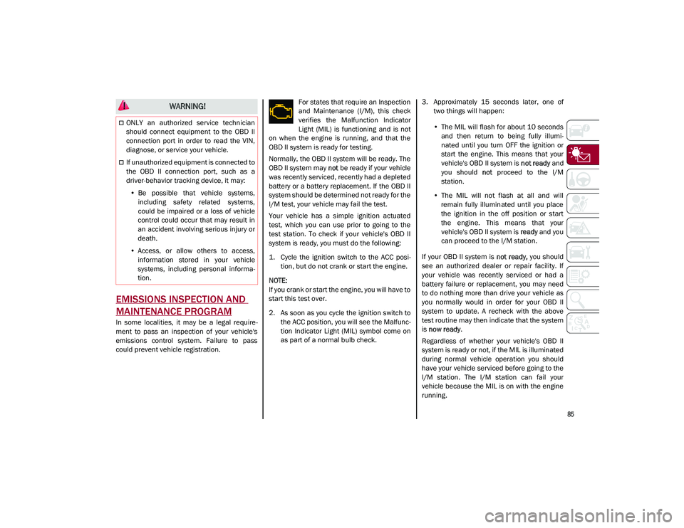
could prevent vehicle registration. For states that require an Inspection
and Maintenance (I/M), this check
verifies the Malfunction Indicator
Light (MIL) is functioning and is not
on when the engine is running, and that the
OBD II system is ready for testing.
Normally, the OBD II system will be ready. The
OBD II system may not be ready if your vehicle
was recently serviced, recently had a depleted
battery or a battery replacement. If the OBD II
system should be determined not ready for the
I/M test, your vehicle may fail the test.
Your vehicle has a simple ignition actuated
test, which you can use prior to going to the
test station. To check if your vehicle's OBD II
system is ready, you must do the following:
1. Cycle the ignition switch to the ACC posi -
tion, but do not crank or start the engine.
NOTE:
If you crank or start the engine, you will have to
start this test over.
2. As soon as you cycle the ignition switch to the ACC position, you will see the Malfunc -
tion Indicator Light (MIL) symbol come on
as part of a normal bulb check. 3. Approximately 15 seconds later, one of
two things will happen:
• The MIL will flash for about 10 seconds
and then return to being fully illumi-
nated until you turn OFF the ignition or
start the engine. This means that your
vehicle's OBD II system is not ready and
you should not proceed to the I/M
station.
• The MIL will not flash at all and will
remain fully illuminated until you place the ignition in the off position or start
the engine. This means that your
vehicle's OBD II system is ready and you
can proceed to the I/M station.
If y o
ur OBD II system is not ready, you should
see an authorized dealer or repair facility. If
your vehicle was recently serviced or had a
battery failure or replacement, you may need
to do nothing more than drive your vehicle as
you normally would in order for your OBD II
system to update. A recheck with the above
test routine may then indicate that the system
is now ready .
Regardless of whether your vehicle's OBD II
system is ready or not, if the MIL is illuminated
during normal vehicle operation you should
have your vehicle serviced before going to the
I/M station. The I/M station can fail your
vehicle because the MIL is on with the engine
running.
WARNING!
ONLY an authorized service technician
should connect equipment to the OBD II
connection port in order to read the VIN,
diagnose, or service your vehicle.
If unauthorized equipment is connected to
the OBD II connection port, such as a
driver-behavior tracking device, it may:
• Be possible that vehicle systems,
including safety related systems,
could be impaired or a loss of vehicle
control could occur that may result in an accident involving serious injury or
death.
• Access, or allow others to access,
information stored in your vehicle
systems, including personal informa-
tion.
21_GU_OM_EN_USC_t.book Page 85
Page 127 of 280
125
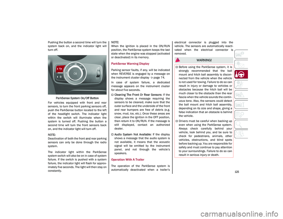
Pushing the button a second time will turn the
system back on, and the indicator light will
turn off.ParkSense System On/Off Button
For vehicles equipped with front and rear
sensors, to turn the front parking sensors off,
push the ParkSense button located to the left
of the headlight switch. The indicator light
within the switch will illuminate when the
system is turned off. Pushing the button a
second time will turn the front sensors back
on, and the indicator light will turn off.
NOTE:
Deactivation of both the front and rear parking
sensors can only be done through the radio
system.
The indicator light within the ParkSense
system switch will also be on in case of system
failure. If the switch is pushed with a system
failure, the indicator light will flash for approx -
imately five seconds. The light will then stay on
constantly.
NOTE:
When the ignition is placed in the ON/RUN
position, the ParkSense system keeps the last
state when the engine was stopped (activated
or deactivated) in its memory.
ParkSense Warning Display
Parking sensor faults, if any, will be indicated
when REVERSE is engaged by a message on
the instrument cluster display
Ú
page 74.
In case of system failure, a dedicated
message appears on the instrument cluster
for about five seconds.
Cleaning The Front Or Rear Sensors : If the
display shows a message requiring the
sensors to be cleaned, make sure that the
outer surface and the underside of the front
and rear bumpers are free of debris (e.g.
snow, mud, ice, etc.). Once these areas are
clear, place the ignition in the OFF position,
then return it to ON/RUN. If the message is
still displayed, contact an authorized
dealer.
Audio System Not Available : If the display
shows a message that the audio system is
not available, it means that the acoustic
signal will be emitted by the instrument
panel, and not through the vehicle’s
speakers.
Operation With A Trailer
The operation of the ParkSense system is
automatically deactivated when a trailer’s electrical connector is plugged into the
vehicle. The sensors are automatically reacti
-
vated when the electrical connector is
removed.
WARNING!
Before using the ParkSense system, it is
strongly recommended that the ball
mount and hitch ball assembly is discon -
nected from the vehicle when the vehicle
is not used for towing. Failure to do so can
result in injury or damage to vehicles or
obstacles because the hitch ball will be
much closer to the obstacle than the rear
fascia when the vehicle sounds the contin -
uous tone. Also, the sensors could detect
the ball mount and hitch ball assembly,
depending on its size and shape, giving a
false indication that an obstacle is behind
the vehicle.
Drivers must be careful when backing up
even when using the ParkSense system.
Always check carefully behind your
vehicle, look behind you, and be sure to
check for pedestrians, animals, other
vehicles, obstructions, and blind spots
before backing up. You are responsible for
safety and must continue to pay attention
to your surroundings. Failure to do so can
result in serious injury or death.
21_GU_OM_EN_USC_t.book Page 125
Page 144 of 280
STARTING AND OPERATING
142
Removing The Receiver
When the receiver is no longer needed, discon-
nect the electrical connections and remove it
from its position using the directions below:
1. Remove the safety split ring from the locking pin.
2. Pull the locking pin out of the trailer hitch.
3. Remove the receiver from the trailer hitch.
SUGGESTIONS FOR DRIVING
Saving Fuel
Below are some suggestions which may help
you save fuel and lower the amount of harmful
emissions released into the atmosphere.
Vehicle Maintenance
Checks and operations should be carried out
in accordance with the Maintenance Plan
Ú
page 208.
Tires
Check the tire pressures at least once every
four weeks: if the pressure is too low,
consumption levels increase as resistance to
rolling is higher.
NOTE:
Tire pressure that is too high can cause
premature tire wear, reduced control, etc. Unnecessary Loads
Do not travel with an overloaded liftgate. The
weight of the vehicle and its arrangement
greatly affect fuel consumption and stability.
Electric Devices
Use electrical systems only for the amount of
time needed. The rear window defroster, addi
-
tional headlights, windshield wipers and
heater blower fan require a considerable
amount of energy; increasing the current
uptake increases fuel consumption (by up to
+25% when city driving).
Climate Control System
Using the climate control system will increase
consumption: use standard ventilation when
the temperature outside permits.
Devices For Aerodynamic Control
The use of non-certified devices for aerody -
namic control may adversely affect air drag
and consumption levels.
Driving Style
Starting
Do not warm up the engine at low or high revs
when the vehicle is stationary; this causes the
engine to warm up more slowly, thereby
increasing fuel consumption and emissions. It
is therefore advisable to drive off immediately,
slowly, avoiding high speeds: by doing this the
engine will warm up more quickly. Unnecessary Actions
Avoid revving up when starting at traffic lights
or before stopping the engine. This action is
unnecessary and causes increased fuel
consumption and pollution.
Gear Selection
Use a high gear when traffic and road condi
-
tions allow it. Using a low gear for faster accel -
eration will increase fuel consumption.
Improper use of a high gear increases
consumption, emissions and engine wear.
Max. Speed
Fuel consumption considerably increases as
speed increases. Maintain a constant speed,
avoiding unnecessary braking and accelera -
tion, which cost in terms of both fuel consump -
tion and emissions.
Acceleration
Accelerating violently severely affects
consumption and emissions: acceleration
should be gradual and should not exceed the
maximum torque.Conditions Of Use
Cold Starting
Short trips and frequent cold starts will not
allow the engine to reach optimum operating
temperature. This results in a significant
increase in consumption levels (from +15 to
+30% in city driving) and emissions.
21_GU_OM_EN_USC_t.book Page 142
Page 145 of 280
143
Traffic And Road Conditions
High fuel consumption is caused by heavy
traffic, for instance when traveling in traffic
with frequent use of low gears or in cities with
many traffic lights. Winding mountain roads
and rough road surfaces also adversely affect
consumption.
Stops In Traffic
During prolonged stops (e.g. railway cross-
ings), turn off the engine.
Performance — Quadrifoglio
This vehicle is equipped with an engine
capable of delivering exceptionally fast accel -
eration and speed:
Peak power: 505 HP at 6,500 RPM.
Peak torque: 443 ft-lbs at 2,500–5,000 RPM.
Top speed: 176 mph (283 km/h).
Acceleration from 0 to 60 mph (0 to 100 km/h):
3.6 seconds.
For safe driving, it is essential, particularly
during the first days of use, to get to know the
car by driving carefully and gradually discov -
ering its performance.
Brakes
The car braking system may be available with
four carbon-ceramic material brake discs, one
on each wheel. In order to guarantee the maximum braking
capacity for the first use, Alfa Romeo performs
a "run-in" procedure for discs and pads directly
at the factory.
The use of carbon-ceramic material brake
discs guarantees braking features (better
deceleration/pedal load ratio, braking
distances, fading resistance) proportional to
the dynamic features of the car in addition to
considerably decreasing the unsprung compo
-
nent weight.
The materials used and the structural features
of the system could generate unusual noises
which have absolutely no adverse effect on
correct operation and reliability of the braking
system.
Greater pressure may need to be applied to
the brake pedal the first time to keep the same
braking capacities in presence of condensa -
tion or salt on the braking surfaces, for
example after washing or if the car is not used
for a long time.
NOTE:
Given the high technological level of this
system, any servicing on it must be performed
by an authorized dealer which exclusively has
the skills needed for the repair and mainte -
nance operations. In case of intensive, high-performance use of
the car, have the efficiency of the
carbon-ceramic material braking system
inspected as shown on the Maintenance Plan
at an authorized dealer.
Driving On Race Tracks
Before driving on a track using a racing style, it
is necessary to:
Attend a race track driving course.
Check the liquid levels in the engine
compartment
Ú
page 208.
Have the car inspected at an authorized
dealer.
Remember that the car was not designed to be
driven exclusively on the race track and that
this use increases stress and component
wear.
NOTE:
Quadrifoglio front brakes are equipped with
Non-Asbestos Organic (NAO) type pads. These
pads are NOT suitable for high thermal loads
(for example track use). If you want to use
vehicle on a track it is recommended to use
the optional CCM Brakes (Carbon Ceramic
Brake disc).
21_GU_OM_EN_USC_t.book Page 143
Page 152 of 280
SAFETY
150
For the operation of the DAA, LDW, LKA, HAS,
TJA, ACC, ISC, or TSR systems, see
Ú
page 86.
NOTE:
When driving on two-way roads where there is
no lane dividing center line (e.g. on unpaved
roads), the use of the ABSA, HAS, TJA, and LKA
systems is strongly discouraged as the system
could detect the entire road as single-lane
dividing lines.
NOTE:
The driving assistance systems are designed
to aid in driving the car. The driver must always
maintain a sufficient level of attention to the
traffic and road conditions and control the
trajectory of the car.
Blind Spot Monitoring (BSM) System — If
Equipped
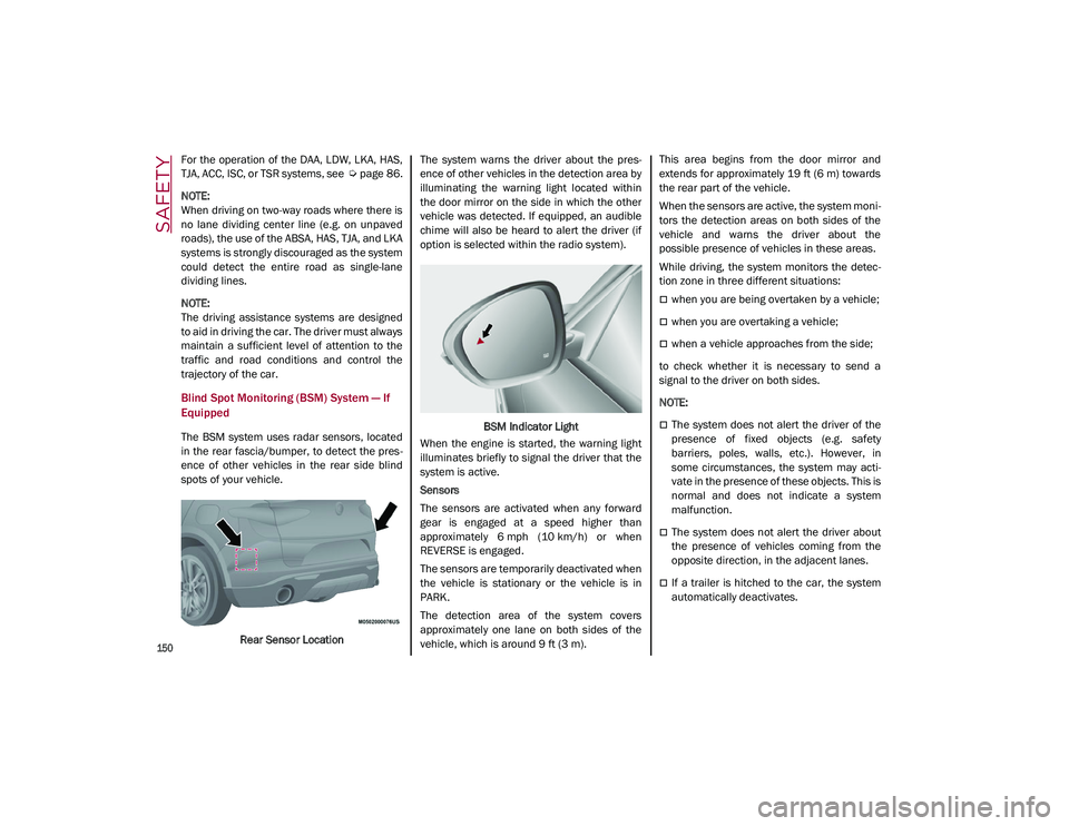
The BSM system uses radar sensors, located
in the rear fascia/bumper, to detect the pres -
ence of other vehicles in the rear side blind
spots of your vehicle.
Rear Sensor Location The system warns the driver about the pres
-
ence of other vehicles in the detection area by
illuminating the warning light located within
the door mirror on the side in which the other
vehicle was detected. If equipped, an audible
chime will also be heard to alert the driver (if
option is selected within the radio system).
BSM Indicator Light
When the engine is started, the warning light
illuminates briefly to signal the driver that the
system is active.
Sensors
The sensors are activated when any forward
gear is engaged at a speed higher than
approximately 6 mph (10 km/h) or when
REVERSE is engaged.
The sensors are temporarily deactivated when
the vehicle is stationary or the vehicle is in
PARK.
The detection area of the system covers
approximately one lane on both sides of the
vehicle, which is around 9 ft (3 m). This area begins from the door mirror and
extends for approximately 19 ft (6 m) towards
the rear part of the vehicle.
When the sensors are active, the system moni
-
tors the detection areas on both sides of the
vehicle and warns the driver about the
possible presence of vehicles in these areas.
While driving, the system monitors the detec -
tion zone in three different situations:
when you are being overtaken by a vehicle;
when you are overtaking a vehicle;
when a vehicle approaches from the side;
to check whether it is necessary to send a
signal to the driver on both sides.
NOTE:
The system does not alert the driver of the
presence of fixed objects (e.g. safety
barriers, poles, walls, etc.). However, in
some circumstances, the system may acti -
vate in the presence of these objects. This is
normal and does not indicate a system
malfunction.
The system does not alert the driver about
the presence of vehicles coming from the
opposite direction, in the adjacent lanes.
If a trailer is hitched to the car, the system
automatically deactivates.
21_GU_OM_EN_USC_t.book Page 150
Page 171 of 280
169
Supplemental Restraint Systems (SRS)
Some of the safety features described in this
section may be standard equipment on some
models, or may be optional equipment on
others. If you are not sure, ask an authorized
dealer.
The air bag system must be ready to protect
you in a collision. The Occupant Restraint
Controller (ORC) monitors the internal circuits
and interconnecting wiring associated with the
electrical Air Bag System Components. Your
vehicle may be equipped with the following Air
Bag System Components:
Air Bag System Components
Occupant Restraint Controller (ORC)
Air Bag Warning Light
Steering Wheel and Column
Instrument Panel
Knee Impact Bolsters
Driver and Front Passenger Air Bags
Seat Belt Buckle Switch
Supplemental Side Air Bags
Supplemental Knee Air Bags
Front and Side Impact Sensors
Seat Belt Pretensioners
Seat Track Position Sensors
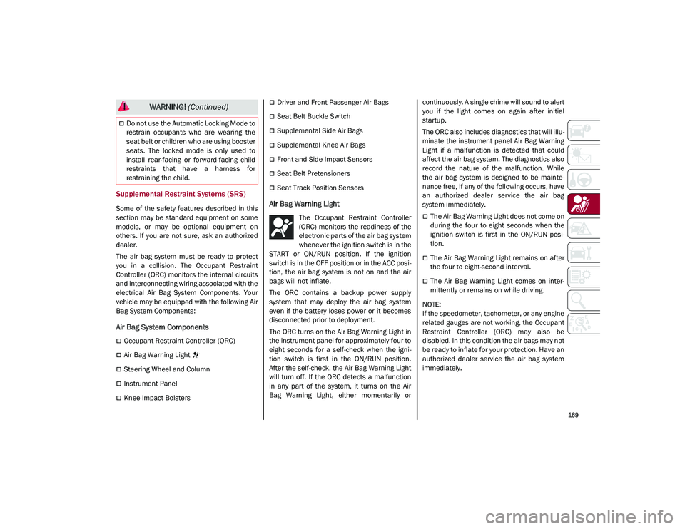
Air Bag Warning Light
The Occupant Restraint Controller
(ORC) monitors the readiness of the
electronic parts of the air bag system
whenever the ignition switch is in the
START or ON/RUN position. If the ignition
switch is in the OFF position or in the ACC posi -
tion, the air bag system is not on and the air
bags will not inflate.
The ORC contains a backup power supply
system that may deploy the air bag system
even if the battery loses power or it becomes
disconnected prior to deployment.
The ORC turns on the Air Bag Warning Light in
the instrument panel for approximately four to
eight seconds for a self-check when the igni -
tion switch is first in the ON/RUN position.
After the self-check, the Air Bag Warning Light
will turn off. If the ORC detects a malfunction
in any part of the system, it turns on the Air
Bag Warning Light, either momentarily or continuously. A single chime will sound to alert
you if the light comes on again after initial
startup.
The ORC also includes diagnostics that will illu
-
minate the instrument panel Air Bag Warning
Light if a malfunction is detected that could
affect the air bag system. The diagnostics also
record the nature of the malfunction. While
the air bag system is designed to be mainte -
nance free, if any of the following occurs, have
an authorized dealer service the air bag
system immediately.The Air Bag Warning Light does not come on
during the four to eight seconds when the
ignition switch is first in the ON/RUN posi -
tion.
The Air Bag Warning Light remains on after
the four to eight-second interval.
The Air Bag Warning Light comes on inter-
mittently or remains on while driving.
NOTE:
If the speedometer, tachometer, or any engine
related gauges are not working, the Occupant
Restraint Controller (ORC) may also be
disabled. In this condition the air bags may not
be ready to inflate for your protection. Have an
authorized dealer service the air bag system
immediately.
Do not use the Automatic Locking Mode to
restrain occupants who are wearing the
seat belt or children who are using booster
seats. The locked mode is only used to
install rear-facing or forward-facing child
restraints that have a harness for
restraining the child.
WARNING! (Continued)
21_GU_OM_EN_USC_t.book Page 169
Page 178 of 280
SAFETY
176
NOTE:
After an accident, remember to cycle the igni-
tion to the OFF position and remove the key
from the ignition switch to avoid draining the
battery. Carefully check the vehicle for fuel
leaks in the engine compartment and on the
ground near the engine compartment and fuel
tank before resetting the system and starting
the engine. If there are no fuel leaks or
damage to the vehicle electrical devices (e.g.
headlights) after an accident, reset the system by following the procedure described below. If
you have any doubt, contact an authorized
dealer.
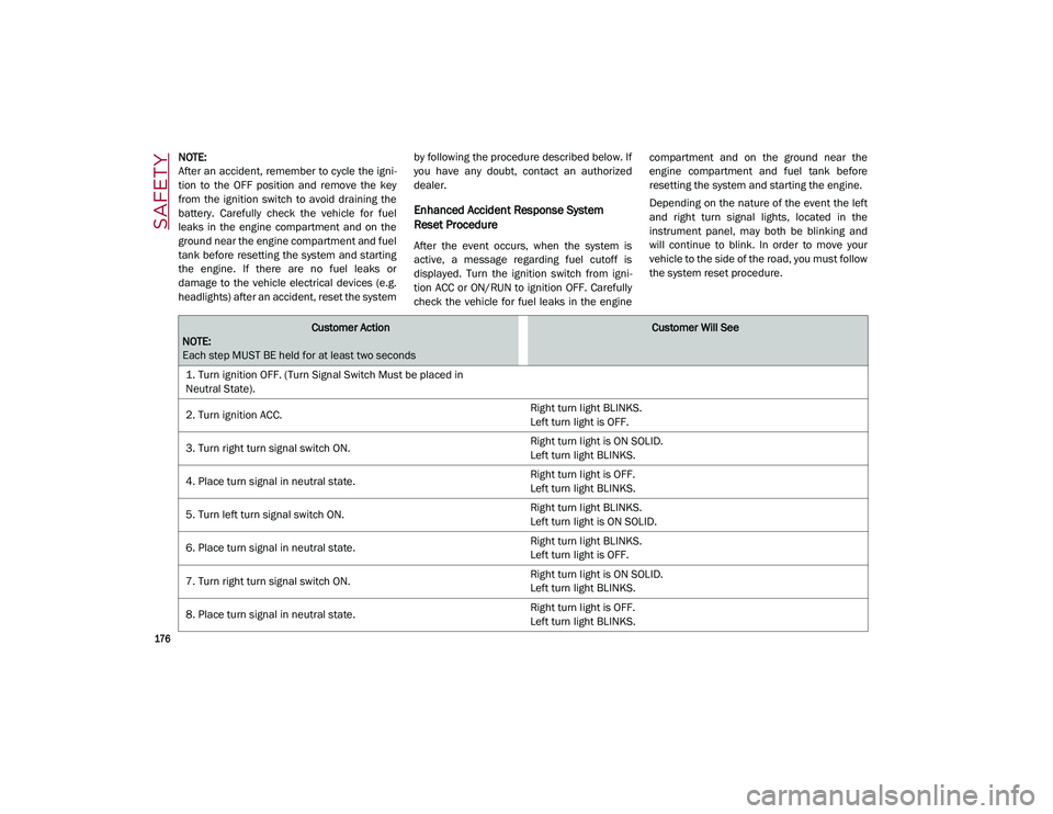
Enhanced Accident Response System
Reset Procedure
After the event occurs, when the system is
active, a message regarding fuel cutoff is
displayed. Turn the ignition switch from igni
-
tion ACC or ON/RUN to ignition OFF. Carefully
check the vehicle for fuel leaks in the engine compartment and on the ground near the
engine compartment and fuel tank before
resetting the system and starting the engine.
Depending on the nature of the event the left
and right turn signal lights, located in the
instrument panel, may both be blinking and
will continue to blink. In order to move your
vehicle to the side of the road, you must follow
the system reset procedure.
Customer Action
NOTE:
Each step MUST BE held for at least two secondsCustomer Will See
1. Turn ignition OFF. (Turn Signal Switch Must be placed in
Neutral State).
2. Turn ignition ACC. Right turn light BLINKS.
Left turn light is OFF.
3. Turn right turn signal switch ON. Right turn light is ON SOLID.
Left turn light BLINKS.
4. Place turn signal in neutral state. Right turn light is OFF.
Left turn light BLINKS.
5. Turn left turn signal switch ON. Right turn light BLINKS.
Left turn light is ON SOLID.
6. Place turn signal in neutral state. Right turn light BLINKS.
Left turn light is OFF.
7. Turn right turn signal switch ON. Right turn light is ON SOLID.
Left turn light BLINKS.
8. Place turn signal in neutral state. Right turn light is OFF.
Left turn light BLINKS.
21_GU_OM_EN_USC_t.book Page 176