ABS ALFA ROMEO STELVIO 2021 Owner's Manual
[x] Cancel search | Manufacturer: ALFA ROMEO, Model Year: 2021, Model line: STELVIO, Model: ALFA ROMEO STELVIO 2021Pages: 280, PDF Size: 10.02 MB
Page 156 of 280
SAFETY
154
The application of torque, as well as of the
vibration, is suppressed/inhibited if:
The torque given by the driver of the
steering wheel is high
Lateral acceleration is high
The trailer is connected to the correct
control module
At least one hand is not detected on the
steering wheel for longer than a specific
time
The turn signal is turned off
NOTE:
The steering wheel torque is not applied if the
system is unable to detect a lane and if the
direction indicator for the appropriate side has
not been switched on.
The steering wheel detects the presence of
the driver’s hands by a capacitive sensor
installed in the steering wheel and by the
applied torque measured on the steering
column.
System availability
Aggressive driving of the car, or driving on the
median lines, will prevent the correct opera -
tion of the system. In case of intervention of the stability and
braking systems (FCW, ESC, ABS) they will
prevent the system from operating.
Lane change will disable the system for a
certain period of time.
The road must also comply with some specific
characteristics, such as:
Maximum/minimum lane width.
Clearly identified and defined double yellow
lines and, for a limited period of time, a lane
with a single demarcation line.
NOTE:
In some cases, for a limited period of time, the
system may be activated by a lane with a
single median line.
In cases of good road surface conditions, the
system could correctly recognize other types
of valid lane markings (e.g. road edges, side -
walks, etc.).
Hands Presence On The Steering Wheel
Detection
The system is able to detect the presence of
the driver’s hands on the steering wheel.
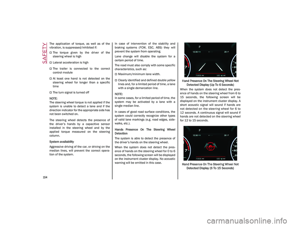
When the system does not detect the pres -
ence of hands on the steering wheel for 0 to 6
seconds, the following screen will be displayed
on the instrument cluster display. No acoustic
warning will be emitted in this case. Hand Presence On The Steering Wheel Not
Detected Display (Up To 6 Seconds)
When the system does not detect the pres -
ence of hands on the steering wheel from 6 to
15 seconds, the following screen will be
displayed on the instrument cluster display. A
short acoustic signal will sound if hands are
not detected on the steering wheel for 6 to
12 seconds. A continuous signal will sound if
hands are not detected on the steering wheel
for 12 to 15 seconds.
Hand Presence On The Steering Wheel Not Detected Display (6 To 15 Seconds)
21_GU_OM_EN_USC_t.book Page 154
Page 157 of 280
155
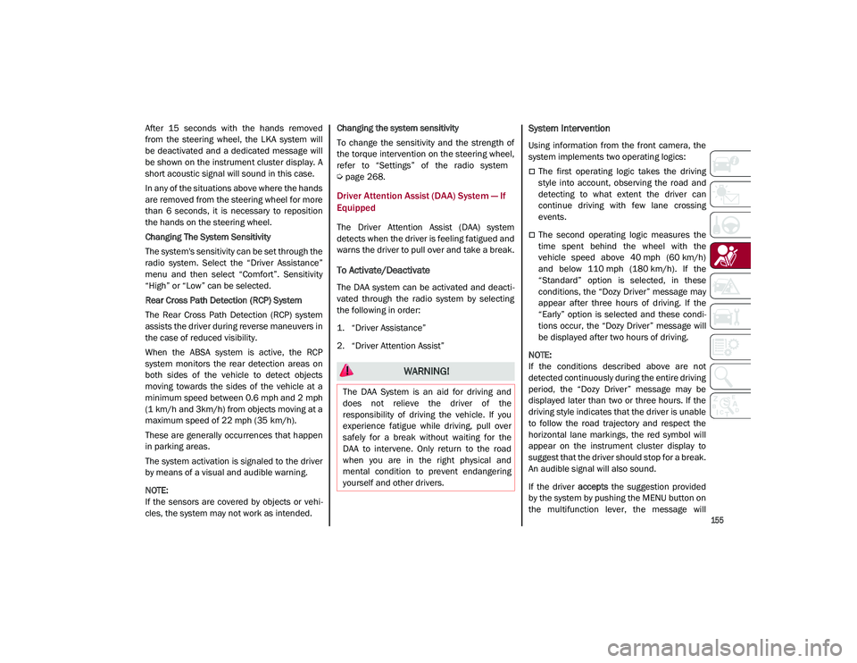
After 15 seconds with the hands removed
from the steering wheel, the LKA system will
be deactivated and a dedicated message will
be shown on the instrument cluster display. A
short acoustic signal will sound in this case.
In any of the situations above where the hands
are removed from the steering wheel for more
than 6 seconds, it is necessary to reposition
the hands on the steering wheel.
Changing The System Sensitivity
The system's sensitivity can be set through the
radio system. Select the “Driver Assistance”
menu and then select “Comfort”. Sensitivity
“High” or “Low” can be selected.
Rear Cross Path Detection (RCP) System
The Rear Cross Path Detection (RCP) system
assists the driver during reverse maneuvers in
the case of reduced visibility.
When the ABSA system is active, the RCP
system monitors the rear detection areas on
both sides of the vehicle to detect objects
moving towards the sides of the vehicle at a
minimum speed between 0.6 mph and 2 mph
(1 km/h and 3km/h) from objects moving at a
maximum speed of 22 mph (35 km/h).
These are generally occurrences that happen
in parking areas.
The system activation is signaled to the driver
by means of a visual and audible warning.
NOTE:
If the sensors are covered by objects or vehi-
cles, the system may not work as intended. Changing the system sensitivity
To change the sensitivity and the strength of
the torque intervention on the steering wheel,
refer to “Settings” of the radio system
Ú
page 268.
Driver Attention Assist (DAA) System — If
Equipped
The Driver Attention Assist (DAA) system
detects when the driver is feeling fatigued and
warns the driver to pull over and take a break.
To Activate/Deactivate
The DAA system can be activated and deacti -
vated through the radio system by selecting
the following in order:
1. “Driver Assistance”
2. “Driver Attention Assist”
System Intervention
Using information from the front camera, the
system implements two operating logics:
The first operating logic takes the driving
style into account, observing the road and
detecting to what extent the driver can
continue driving with few lane crossing
events.
The second operating logic measures the
time spent behind the wheel with the
vehicle speed above 40 mph (60 km/h) and below 110 mph (180 km/h). If the“Standard” option is selected, in these
conditions, the “Dozy Driver” message may
appear after three hours of driving. If the
“Early” option is selected and these condi -
tions occur, the “Dozy Driver” message will
be displayed after two hours of driving.
NOTE:
If the conditions described above are not
detected continuously during the entire driving
period, the “Dozy Driver” message may be
displayed later than two or three hours. If the
driving style indicates that the driver is unable
to follow the road trajectory and respect the
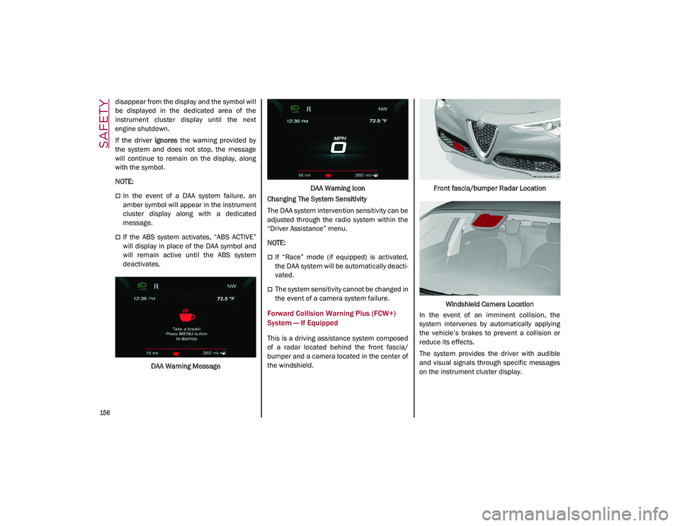
horizontal lane markings, the red symbol will
appear on the instrument cluster display to
suggest that the driver should stop for a break.
An audible signal will also sound.
If the driver accepts the suggestion provided
by the system by pushing the MENU button on
the multifunction lever, the message will
WARNING!
The DAA System is an aid for driving and
does not relieve the driver of the
responsibility of driving the vehicle. If you
experience fatigue while driving, pull over
safely for a break without waiting for the
DAA to intervene. Only return to the road
when you are in the right physical and
mental condition to prevent endangering
yourself and other drivers.
21_GU_OM_EN_USC_t.book Page 155
Page 158 of 280
SAFETY
156
disappear from the display and the symbol will
be displayed in the dedicated area of the
instrument cluster display until the next
engine shutdown.
If the driver ignores the warning provided by
the system and does not stop, the message
will continue to remain on the display, along
with the symbol.
NOTE:
In the event of a DAA system failure, an
amber symbol will appear in the instrument
cluster display along with a dedicated
message.
If the ABS system activates, “ABS ACTIVE”
will display in place of the DAA symbol and
will remain active until the ABS system
deactivates.
DAA Warning Message DAA Warning Icon
Changing The System Sensitivity
The DAA system intervention sensitivity can be
adjusted through the radio system within the
“Driver Assistance” menu.
NOTE:
If “Race” mode (if equipped) is activated,
the DAA system will be automatically deacti -
vated.
The system sensitivity cannot be changed in
the event of a camera system failure.
Forward Collision Warning Plus (FCW+)
System — If Equipped
This is a driving assistance system composed
of a radar located behind the front fascia/
bumper and a camera located in the center of
the windshield. Front fascia/bumper Radar Location
Windshield Camera Location
In the event of an imminent collision, the
system intervenes by automatically applying
the vehicle’s brakes to prevent a collision or
reduce its effects.
The system provides the driver with audible
and visual signals through specific messages
on the instrument cluster display.
21_GU_OM_EN_USC_t.book Page 156
Page 161 of 280
159
The function of this system can also be tempo-
rarily reduced due to obstructions such as
mud, dirt or ice on the fascia/bumper. In such
cases, a dedicated message will be shown on
the display and the system will be deactivated.
This message can sometimes appear in condi -
tions of high reflectivity (e.g. tunnels with
reflective tiles or ice or snow). When the condi -
tions limiting the system functions end, it will
go back to normal and complete operation.
In certain cases, this dedicated message
could be displayed when the radar is not
detecting any vehicles or objects within its
view range.
If atmospheric conditions are not the reason
behind this message, check if the sensor is
dirty. It could be necessary to clean or remove
any obstructions in the area.
If the message appears frequently, even in the
absence of atmospheric conditions such as
snow, rain, mud or other obstructions, contact
an authorized dealer for a sensor alignment
check.
In the absence of visible obstructions, manu -
ally removing the decorative cover trim and
cleaning the radar surface could be required.
Have this operation performed at an autho -
rized dealer.
NOTE:
It is recommended that you do not install
devices, accessories or aerodynamic attach
-
ments in front of the sensor or darken it in any
way, as this can compromise the correct func -
tioning of the system.
Frontal Collision Alarm With Active Braking — If
Equipped
If this function is selected, the brakes are
operated to reduce the speed of the vehicle in
the event of potential frontal impact.
This function applies an additional braking
pressure if the braking pressure applied by the
driver does not suffice to prevent potential
frontal impact.
The function is active with speed above 2 mph
(4 km/h).
NOTE:
When using an automatic car wash it is recom -
mended to deactivate the system through the
settings of the radio system. The system may
detect the presence of a car, a wall or another
obstacle and activate.
Driving In Special Conditions
In certain driving conditions, system interven -
tion might be unexpected or delayed. The
driver must therefore be very careful, keeping
control of the vehicle to drive in complete
safety.Driving close to a bend.
The vehicle ahead is leaving a roundabout.
Vehicles with small dimensions and/or not
aligned in the driving lane.
Lane change by other vehicles.
Vehicles traveling at right angles to the
vehicle.
NOTE:
In particularly complex traffic conditions,
the driver can deactivate the system manu -
ally through the Information and Entertain -
ment system.
If the driver depresses the brake pedal fully
or makes an excessive steering maneuver
during system operation, the automatic
braking function may deactivate (e.g. to
allow a possible maneuver to avoid the
obstacle).
The FCW system is automatically deacti -
vated when operating in race mode and a
warning message will be displayed on the
instrument cluster.
21_GU_OM_EN_USC_t.book Page 159
Page 174 of 280
SAFETY
172
damage by themselves are not good indicators
of whether or not an air bag should have
deployed.
Seat belts are necessary for your protection in
all collisions, and also are needed to help keep
you in position, away from an inflating air bag.
When the Occupant Restraint Controller (ORC)
detects a collision requiring the front air bags,
it signals the inflator units. A large quantity of
non-toxic gas is generated to inflate the front
air bags.
The steering wheel hub trim cover and the
upper passenger side of the instrument panel
separate and fold out of the way as the air
bags inflate to their full size. The front air bags
fully inflate in less time than it takes to blink
your eyes. The front air bags then quickly
deflate while helping to restrain the driver and
front passenger.
Knee Impact Bolsters
The Knee Impact Bolsters help protect the
knees of the driver and front passenger, and
position the front occupants for improved
interaction with the front air bags.
Supplemental Driver And Front Passenger
Knee Air Bags
This vehicle is equipped with a Supplemental
Driver Knee Air Bag mounted in the instrument
panel below the steering column and a
Supplemental Passenger Knee Air Bag
mounted in the instrument panel below the
glove compartment. The Supplemental Knee
Air Bags provide enhanced protection during a
frontal impact by working together with the
seat belts, pretensioners, and front air bags.
Supplemental Side Air Bags
Supplemental Seat-Mounted Side Air Bags
(SABs)
This vehicle is equipped with Supplemental
Seat-Mounted Side Air Bags (SABs).
Supplemental Seat-Mounted Side Air Bags
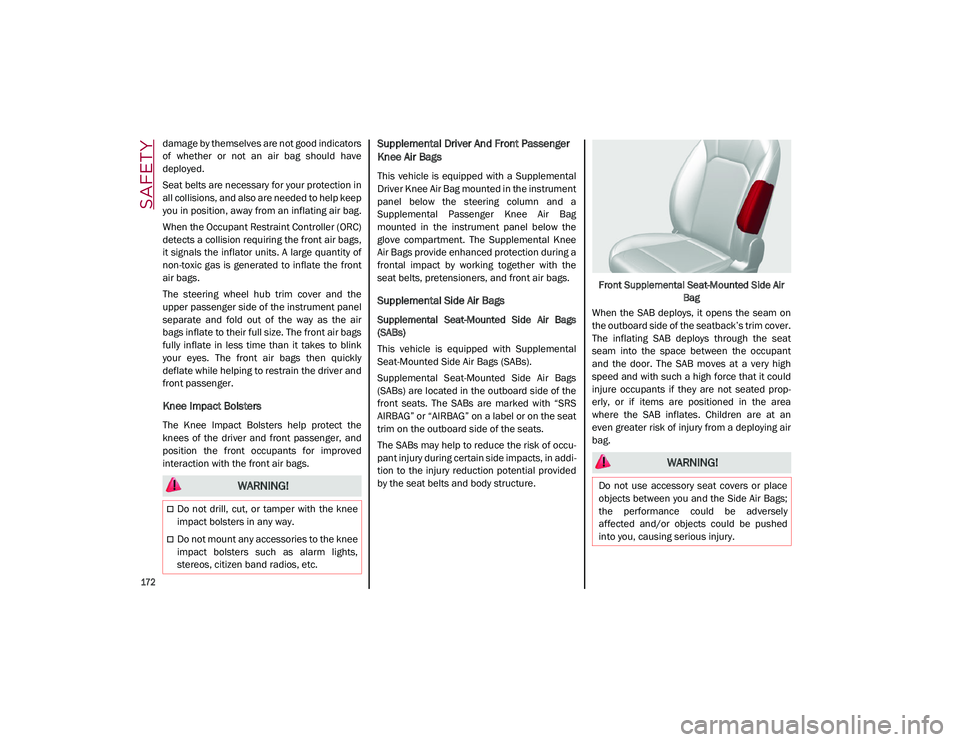
(SABs) are located in the outboard side of the
front seats. The SABs are marked with “SRS
AIRBAG” or “AIRBAG” on a label or on the seat
trim on the outboard side of the seats.
The SABs may help to reduce the risk of occu-
pant injury during certain side impacts, in addi-
tion to the injury reduction potential provided
by the seat belts and body structure. Front Supplemental Seat-Mounted Side Air
Bag
When the SAB deploys, it opens the seam on
the outboard side of the seatback’s trim cover.
The inflating SAB deploys through the seat
seam into the space between the occupant
and the door. The SAB moves at a very high
speed and with such a high force that it could
injure occupants if they are not seated prop -
erly, or if items are positioned in the area
where the SAB inflates. Children are at an
even greater risk of injury from a deploying air
bag.
WARNING!
Do not drill, cut, or tamper with the knee
impact bolsters in any way.
Do not mount any accessories to the knee
impact bolsters such as alarm lights,
stereos, citizen band radios, etc.
WARNING!
Do not use accessory seat covers or place
objects between you and the Side Air Bags;
the performance could be adversely
affected and/or objects could be pushed
into you, causing serious injury.
21_GU_OM_EN_USC_t.book Page 172
Page 201 of 280
199
(Continued)
An instruction pamphlet for reference in
prompt and correct use of the Tire Service
Kit, which must be then given to the
personnel dealing with the sealant-treated
tire
A pair of protective gloves
Some adapters, for inflating different
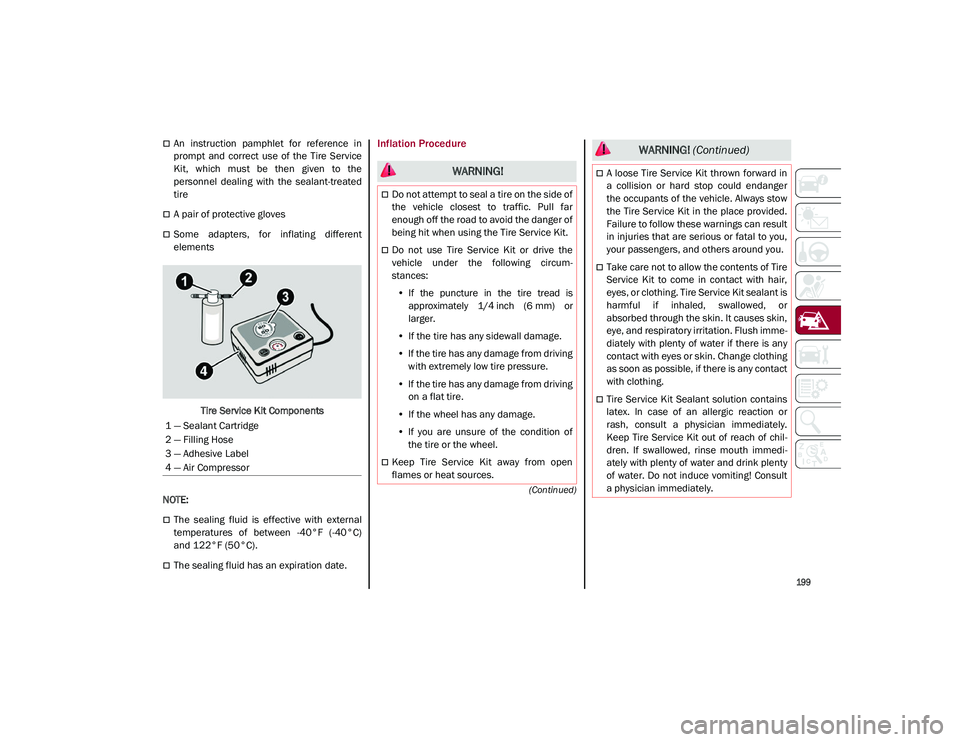
elementsTire Service Kit Components
NOTE:
The sealing fluid is effective with external
temperatures of between -40°F (-40°C)
and 122°F (50°C).
The sealing fluid has an expiration date.
Inflation Procedure
1 — Sealant Cartridge
2 — Filling Hose
3 — Adhesive Label
4 — Air Compressor
WARNING!
Do not attempt to seal a tire on the side of
the vehicle closest to traffic. Pull far
enough off the road to avoid the danger of
being hit when using the Tire Service Kit.
Do not use Tire Service Kit or drive the
vehicle under the following circum -
stances:
• If the puncture in the tire tread is
approximately 1/4 inch (6 mm) or
larger.
• If the tire has any sidewall damage.
• If the tire has any damage from driving
with extremely low tire pressure.
• If the tire has any damage from driving
on a flat tire.
• If the wheel has any damage.
• If you are unsure of the condition of
the tire or the wheel.
Keep Tire Service Kit away from open
flames or heat sources.
A loose Tire Service Kit thrown forward in
a collision or hard stop could endanger
the occupants of the vehicle. Always stow
the Tire Service Kit in the place provided.
Failure to follow these warnings can result
in injuries that are serious or fatal to you,
your passengers, and others around you.
Take care not to allow the contents of Tire
Service Kit to come in contact with hair,
eyes, or clothing. Tire Service Kit sealant is
harmful if inhaled, swallowed, or
absorbed through the skin. It causes skin,
eye, and respiratory irritation. Flush imme -
diately with plenty of water if there is any
contact with eyes or skin. Change clothing
as soon as possible, if there is any contact
with clothing.
Tire Service Kit Sealant solution contains
latex. In case of an allergic reaction or
rash, consult a physician immediately.
Keep Tire Service Kit out of reach of chil -
dren. If swallowed, rinse mouth immedi -
ately with plenty of water and drink plenty
of water. Do not induce vomiting! Consult
a physician immediately.
WARNING! (Continued)
21_GU_OM_EN_USC_t.book Page 199
Page 227 of 280
225
Automatic Transmission
Use only a transmission oil with the character-
istics indicated
Ú
page 263.
Special Additives
Do not use any type of additive with the auto -
matic transmission oil. The automatic trans -
mission oil is a product designed specially for this vehicle and its performance may be
compromised through the use of further addi
-
tives.
Frequency of Oil Changes
In normal vehicle operating conditions, it is not
necessary to change the transmission oil.
Replacing The Battery
If necessary, replace the battery with another
battery with the same specifications. It is
advised to contact an authorized dealer for
replacement.
Follow the battery manufacturer's instructions
for maintenance.
Fuses
General Information
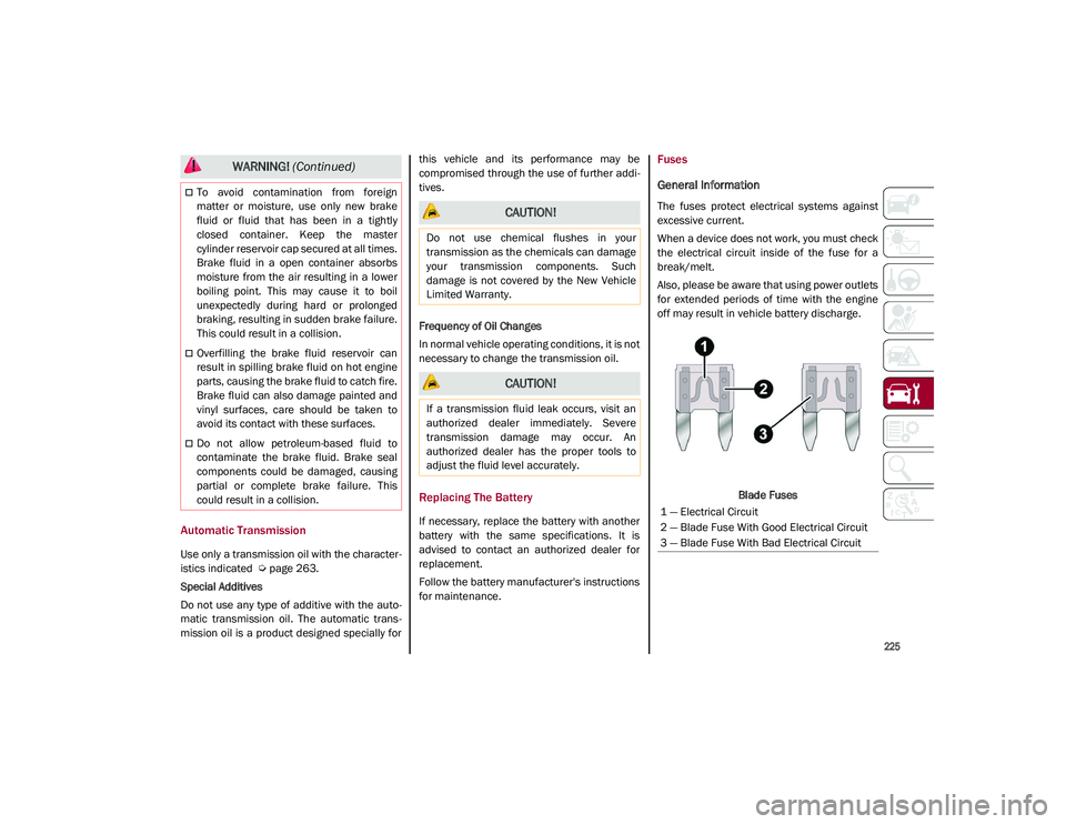
The fuses protect electrical systems against
excessive current.
When a device does not work, you must check
the electrical circuit inside of the fuse for a
break/melt.
Also, please be aware that using power outlets
for extended periods of time with the engine
off may result in vehicle battery discharge.
Blade Fuses
To avoid contamination from foreign
matter or moisture, use only new brake
fluid or fluid that has been in a tightly
closed container. Keep the master
cylinder reservoir cap secured at all times.
Brake fluid in a open container absorbs
moisture from the air resulting in a lower
boiling point. This may cause it to boil
unexpectedly during hard or prolonged
braking, resulting in sudden brake failure.
This could result in a collision.
Overfilling the brake fluid reservoir can
result in spilling brake fluid on hot engine
parts, causing the brake fluid to catch fire.
Brake fluid can also damage painted and
vinyl surfaces, care should be taken to
avoid its contact with these surfaces.
Do not allow petroleum-based fluid to
contaminate the brake fluid. Brake seal
components could be damaged, causing
partial or complete brake failure. This
could result in a collision.
WARNING! (Continued)
CAUTION!
Do not use chemical flushes in your
transmission as the chemicals can damage
your transmission components. Such
damage is not covered by the New Vehicle
Limited Warranty.
CAUTION!
If a transmission fluid leak occurs, visit an
authorized dealer immediately. Severe
transmission damage may occur. An
authorized dealer has the proper tools to
adjust the fluid level accurately.
1 — Electrical Circuit
2 — Blade Fuse With Good Electrical Circuit
3 — Blade Fuse With Bad Electrical Circuit
21_GU_OM_EN_USC_t.book Page 225
Page 228 of 280
SERVICING AND MAINTENANCE
226
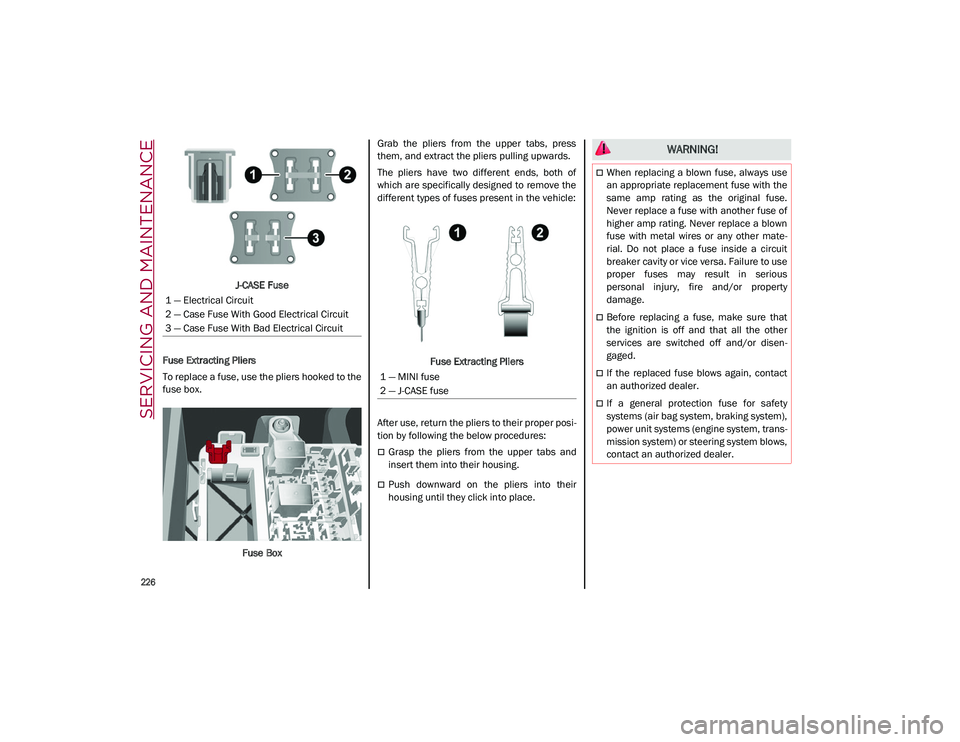
J-CASE Fuse
Fuse Extracting Pliers
To replace a fuse, use the pliers hooked to the
fuse box.
Fuse Box Grab the pliers from the upper tabs, press
them, and extract the pliers pulling upwards.
The pliers have two different ends, both of
which are specifically designed to remove the
different types of fuses present in the vehicle:
Fuse Extracting Pliers
After use, return the pliers to their proper posi -
tion by following the below procedures:
Grasp the pliers from the upper tabs and
insert them into their housing.
Push downward on the pliers into their
housing until they click into place.
1 — Electrical Circuit
2 — Case Fuse With Good Electrical Circuit
3 — Case Fuse With Bad Electrical Circuit
1 — MINI fuse
2 — J-CASE fuse
WARNING!
When replacing a blown fuse, always use
an appropriate replacement fuse with the
same amp rating as the original fuse.
Never replace a fuse with another fuse of
higher amp rating. Never replace a blown
fuse with metal wires or any other mate
-
rial. Do not place a fuse inside a circuit
breaker cavity or vice versa. Failure to use
proper fuses may result in serious
personal injury, fire and/or property
damage.
Before replacing a fuse, make sure that
the ignition is off and that all the other
services are switched off and/or disen -
gaged.
If the replaced fuse blows again, contact
an authorized dealer.
If a general protection fuse for safety
systems (air bag system, braking system),
power unit systems (engine system, trans -
mission system) or steering system blows,
contact an authorized dealer.
21_GU_OM_EN_USC_t.book Page 226
Page 236 of 280
SERVICING AND MAINTENANCE
234
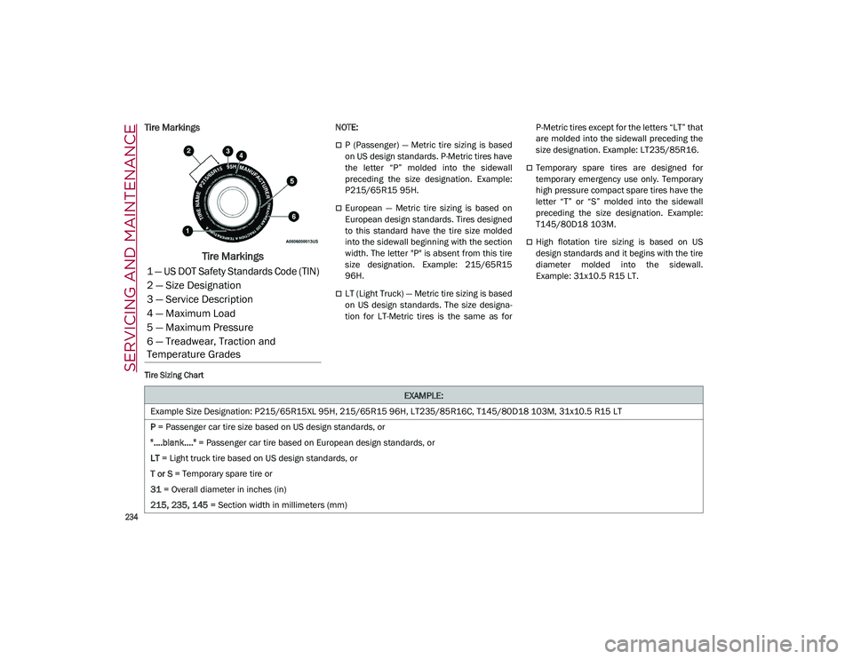
Tire Markings
Tire Markings
NOTE:
P (Passenger) — Metric tire sizing is based
on US design standards. P-Metric tires have
the letter “P” molded into the sidewall
preceding the size designation. Example:
P215/65R15 95H.
European — Metric tire sizing is based on
European design standards. Tires designed
to this standard have the tire size molded
into the sidewall beginning with the section
width. The letter "P" is absent from this tire
size designation. Example: 215/65R15
96H.
LT (Light Truck) — Metric tire sizing is based
on US design standards. The size designa-
tion for LT-Metric tires is the same as for P-Metric tires except for the letters “LT” that
are molded into the sidewall preceding the
size designation. Example: LT235/85R16.
Temporary spare tires are designed for
temporary emergency use only. Temporary
high pressure compact spare tires have the
letter “T” or “S” molded into the sidewall
preceding the size designation. Example:
T145/80D18 103M.
High flotation tire sizing is based on US
design standards and it begins with the tire
diameter molded into the sidewall.
Example: 31x10.5 R15 LT.
Tire Sizing Chart
1 — US DOT Safety Standards Code (TIN)
2 — Size Designation
3 — Service Description
4 — Maximum Load
5 — Maximum Pressure
6 — Treadwear, Traction and
Temperature Grades
EXAMPLE:
Example Size Designation: P215/65R15XL 95H, 215/65R15 96H, LT235/85R16C, T145/80D18 103M, 31x10.5 R15 LT
P = Passenger car tire size based on US design standards, or
"....blank...." = Passenger car tire based on European design standards, or
LT = Light truck tire based on US design standards, or
T or S = Temporary spare tire or
31 = Overall diameter in inches (in)
215, 235, 145 = Section width in millimeters (mm)
21_GU_OM_EN_USC_t.book Page 234
Page 237 of 280
235
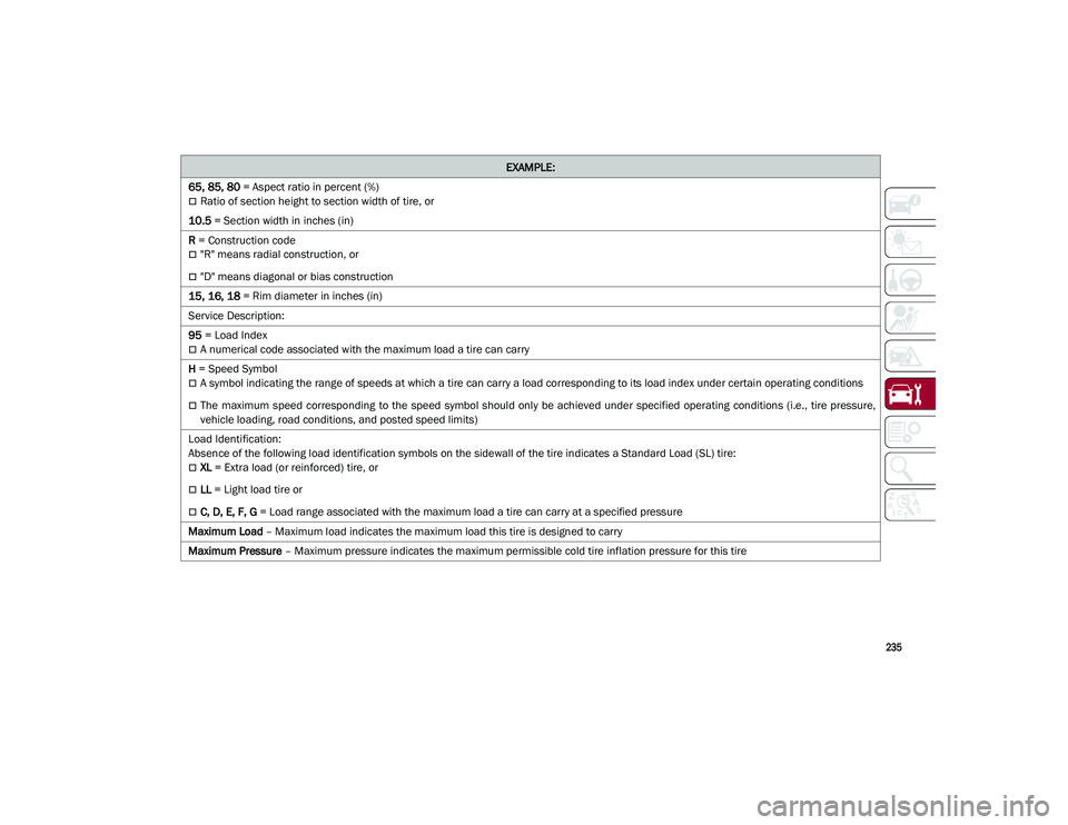
65, 85, 80 = Aspect ratio in percent (%)
Ratio of section height to section width of tire, or
10.5 = Section width in inches (in)
R = Construction code
"R" means radial construction, or
"D" means diagonal or bias construction
15, 16, 18 = Rim diameter in inches (in)
Service Description:
95 = Load Index
A numerical code associated with the maximum load a tire can carry
H = Speed Symbol
A symbol indicating the range of speeds at which a tire can carry a load corresponding to its load index under certain operating conditions
The maximum speed corresponding to the speed symbol should only be achieved under specified operating conditions (i.e., tire pressure,
vehicle loading, road conditions, and posted speed limits)
Load Identification:
Absence of the following load identification symbols on the sidewall of the tire indicates a Standard Load (SL) tire:
XL = Extra load (or reinforced) tire, or
LL = Light load tire or
C, D, E, F, G = Load range associated with the maximum load a tire can carry at a specified pressure
Maximum Load – Maximum load indicates the maximum load this tire is designed to carry
Maximum Pressure – Maximum pressure indicates the maximum permissible cold tire inflation pressure for this tire
EXAMPLE:
21_GU_OM_EN_USC_t.book Page 235