air condition ALFA ROMEO STELVIO 2021 Owners Manual
[x] Cancel search | Manufacturer: ALFA ROMEO, Model Year: 2021, Model line: STELVIO, Model: ALFA ROMEO STELVIO 2021Pages: 280, PDF Size: 10.02 MB
Page 14 of 280
12
JUMP STARTING .................................... 201
Remote Battery Connection Posts......202
Jump Starting Procedure.....................203
Bump Starting ..................................204
ENGINE OVERHEATING ......................... 204 MANUAL PARK RELEASE ...................... 205TOWING A DISABLED VEHICLE ............. 205
Four-Wheel Drive (AWD) Models .........206
TOW EYES .............................................. 206
ENHANCED ACCIDENT RESPONSE
SYSTEM (EARS) ..................................... 207EVENT DATA RECORDER (EDR) ............ 207
SERVICING AND MAINTENANCE
SCHEDULED SERVICING ....................... 208
Periodic Checks ...................................208
Heavy Usage Of The Vehicle ...............208
Maintenance Plan (2.0L Engine) ........209
Maintenance Plan (2.9L Engine) ........212
ENGINE COMPARTMENT....................... 214
Checking Levels — 2.0L Engine .......... 214
Checking Levels — 2.9L Engine .......... 215
Engine Oil ............................................. 215
Engine Coolant Fluid............................216
Washer Fluid For Windshield/
Headlights ............................................ 217 Brake Fluid ...........................................217
Automatic Transmission Activation
System Oil ............................................ 217 Useful Advice For Extending The Life Of
Your Battery..........................................217 Battery ..................................................217
Pressure Washing ................................ 218
BATTERY RECHARGING ......................... 218
Important Notes .................................. 218
VEHICLE MAINTENANCE ........................ 219
Engine Oil ............................................. 219
Engine Oil Filter ................................... 220
Engine Air Cleaner Filter ..................... 220
Air Conditioning System
Maintenance........................................ 220 Lubricating Moving Parts Of The
Bodywork ............................................. 220 Windshield Wiper................................. 221
Exhaust System ................................... 222
Cooling System .................................... 223
Braking System.................................... 224
Automatic Transmission ..................... 225
Replacing The Battery ......................... 225
Fuses .................................................... 225
Bulb Replacement ............................... 229
TIRES ...................................................... 233
Tire Safety Information .................... 233
Tires — General Information .............. 239
Spare Tires — If Equipped .................. 244
Wheel And Wheel Trim Care ............ 245
Tire Types ............................................. 246
Tire Chains and Traction Devices ....... 247
Tire Rotation Recommendations........ 247
DEPARTMENT OF TRANSPORTATION
UNIFORM TIRE QUALITY GRADES ......... 248
Treadwear ............................................ 248
Traction Grades ................................... 248
Temperature Grades ........................... 248
STORING THE VEHICLE ......................... 249 BODYWORK ........................................... 249
Protection Against Atmospheric
Agents .................................................. 249 Corrosion Warranty ............................. 250
Preserving The Bodywork .................. 250
INTERIORS ............................................. 251
Seats And Fabric Parts ....................... 251
Leather Seats ...................................... 251
Plastic And Coated Parts .................... 251
Alcantara Parts — If Equipped ............ 251
Genuine Leather Parts........................ 251
Carbon Fiber Parts .............................. 252
TECHNICAL SPECIFICATIONS
VEHICLE IDENTIFICATION
NUMBER (VIN) ....................................... 253
Vehicle Identification Number............ 253
Vehicle Identification Number
(VIN) Plate ............................................ 253
ENGINE .................................................. 254
POWER SUPPLY ..................................... 255 TRANSMISSION ..................................... 255BRAKES.................................................. 255
SUSPENSION ......................................... 256
STEERING .............................................. 256
DIMENSIONS ......................................... 257
Luggage Compartment Volume ......... 259
WEIGHTS ................................................ 259
21_GU_OM_EN_USC_t.book Page 12
Page 50 of 280
GETTING TO KNOW YOUR VEHICLE
48
If the windshield washer is used with the rain
sensor activated, the normal washing cycle is
performed, and then the rain sensor resumes
its normal automatic operation.
NOTE:
Keep the glass in the sensor area clean.
Deactivation
To turn off the Rain Sensing Wipers, use the
wiper switch or place the ignition in the OFF
position.
In the event of malfunction of the rain sensor
while it is active, the windshield wiper oper-
ates intermittently at a speed consistent with
the sensitivity setting of the rain sensor,
whether or not there is rain on the glass for as
long as the sensor failure is indicated on the
display.
The sensor continues to operate and it is
possible to set the windshield wiper to contin -
uous mode (1 or 2). The failure indication
remains on for as long as the sensor is active. The rain sensor is able to recognize and auto
-
matically adjust itself in the presence of the
following conditions:
Presence of dirt on the controlled surface
(e.g. salt, dirt, etc.).
Presence of streaks of water caused by the
worn window wiper blades.
Difference between day and night.
Rear Window Wiper/Washer
Push the windshield wiper lever downward to
activate/deactivate continuous rear wiper
operation.
Push the windshield wiper lever towards the
instrument panel to activate the rear window
washer (a brief push activates one washing
cycle, keeping the stalk pushed washes
continuously until the stalk is released).
Shifting the vehicle into REVERSE with the
windshield wiper operating activates a single
cycle of the rear window wiper.
Headlamp Washers — If Equipped
The windshield wiper lever operates the head -
light washers when the ignition is in the ON
position and the headlights are turned on. To
use the headlight washers, pull the lever
toward you and release it. The headlight
washers will spray a timed high-pressure spray
of washer fluid onto each headlight lens. In
addition, the windshield washers will spray the
windshield and the windshield wipers will
cycle.
NOTE:
The headlight washers work on every tenth
wash cycle request.
CLIMATE CONTROLS
The Climate Control system allows you to regu -
late the temperature, air flow, and direction of
air circulating throughout the vehicle. The
controls are located on the touchscreen and
on the instrument panel below the radio.
21_GU_OM_EN_USC_t.book Page 48
Page 51 of 280
49
Automatic Dual-Zone Climate Control System
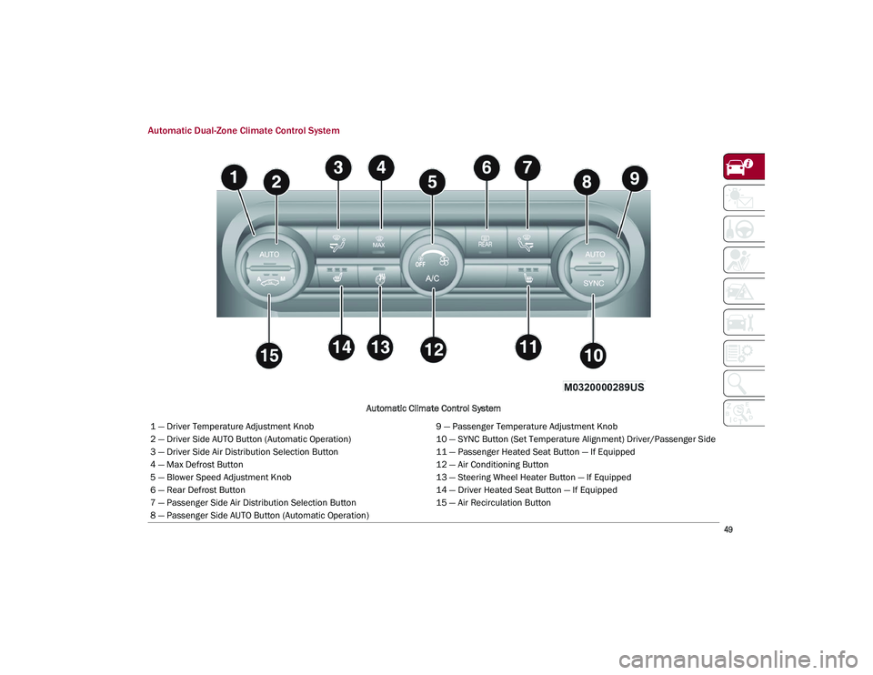
Automatic Climate Control System
1 — Driver Temperature Adjustment Knob 9 — Passenger Temperature Adjustment Knob
2 — Driver Side AUTO Button (Automatic Operation) 10 — SYNC Button (Set Temperature Alignment) Driver/Passenger Side
3 — Driver Side Air Distribution Selection Button 11 — Passenger Heated Seat Button — If Equipped
4 — Max Defrost Button 12 — Air Conditioning Button
5 — Blower Speed Adjustment Knob 13 — Steering Wheel Heater Button — If Equipped
6 — Rear Defrost Button 14 — Driver Heated Seat Button — If Equipped
7 — Passenger Side Air Distribution Selection Button 15 — Air Recirculation Button
8 — Passenger Side AUTO Button (Automatic Operation)
21_GU_OM_EN_USC_t.book Page 49
Page 54 of 280
GETTING TO KNOW YOUR VEHICLE
52
NOTE:
When the A/C is off, the Climate Control
system can not produce air that is colder than
the current outside temperature. Under
certain environmental conditions, windows
could fog up rapidly since the air is not dehu-
midified.
Air Recirculation And Air Quality System (AQS)
Air Recirculation is managed
according to the following operating
mode:
Automatic engagement: indicator is illumi -
nated above the “A” on the Air Recirculation
Button
Forced activation (air circulation always
activated): indicator illuminated above the
icon on the Air Recirculation Button
Forced deactivation (air recirculation
always off with intake of outside air): both
indicators not illuminated on the Air Recir-
culation Button
The three operating conditions are obtained by
pushing the Air Recirculation Button in
sequence.
Enabling The Air Quality System (AQS) Func -
tion — If Equipped
When the automatic recirculation function is
selected, the AQS function automatically acti -
vates internal air recirculation when the
outside air is polluted (e.g. in heavy traffic and
tunnels). At low external temperatures or in high
humidity, the automatic function turns off to
avoid fogging up the windows. The user can
select the function again by pushing the Air
Recirculation Button.
In automatic operation, air recirculation will be
controlled by the system according to outside
environmental conditions.
NOTE:
With the AQS function active and after the
internal air recirculation system has been
functioning for a set amount of time, the
Climate Control System enables air intake
to cycle the air in the passenger compart
-
ment for a set time. The AQS function is
disabled during the air changes.
The engagement of the recirculation system
makes it possible to reach the required
heating or cooling conditions faster. It is,
however, inadvisable to use it on rainy/cold
days as it can increase the possibility of the
windows fogging. When the outside
temperature is low, recirculation is forced
off to prevent the windows from fogging up.
Front Defrost
Air comes from the windshield and
side window demist outlets. Use
Defrost mode with maximum
temperature settings for best wind -
shield and side window defrosting and defog -
ging.
Rear Defrost
Push the Rear Defrost button to acti -
vate (indicators illuminated) the
Rear Defroster.
The Rear Defrost will turn off after 20 minutes
or once the engine is turned off.
NOTE:
To avoid damage, do not apply stickers over
the interior heating filaments of the Rear
Defroster.
Front Defrost And MAX-DEF Function
Push the MAX-DEF button (indicator
illuminated) to defrost the wind -
shield and side windows.
While in MAX-DEF function, the air conditioner
will:
Activate the air conditioner compressor
when the weather allows
Turn air recirculation off
Set the maximum air temperature (HI) on
both the driver and passenger side
Activate a blower speed based on the
temperature of the engine coolant
Adjust the air flow towards the windshield
and front side windows
Activate the Rear Window Defrost
Display the fan speed (indicators illumi -
nated) and current air distribution setting
21_GU_OM_EN_USC_t.book Page 52
Page 55 of 280
53
NOTE:
The MAX-DEF function remains active for
approximately three minutes once the engine
coolant reaches the proper temperature.
When the function is on, AUTO mode will deac-
tivate. The only manual operations possible
are adjusting blower speed and turning off the
Rear Window Defrost.
Pushing the button switches off the
MAX-DEF function.
Air Temperature Adjustment
Rotate the driver or passenger Temperature
Adjustment Knob clockwise for warmer
temperatures or counterclockwise for cooler
temperatures. The set temperatures are
shown on the radio system.
Push the SYNC button to sync the driver and
passenger air temperatures.
Rotate the passenger Temperature Adjust -
ment Knob to cancel the SYNC function. This
will set a new passenger side temperature.
Rotate the Temperature Adjustment Knob fully
clockwise to engage the HI (maximum heating)
setting or fully counterclockwise to engage the
LO (maximum cooling) setting. To deactivate
these functions, rotate the Temperature
Adjustment Knob to the desired temperature.
Rear passengers’ temperature is linked to
driver side selection.
AUTO Button
When the AUTO button is pushed (indicator
illuminated), the Climate Control system auto -
matically adjusts the following settings:
Quantity and distribution of air flow in the
passenger compartment
The air conditioner
Air recirculation
Cancels any manual settings
Selecting the AUTO function illuminates the
indicator on the A/C button.
If air distribution or the fan speed is manually
adjusted, the AUTO button indicator will turn
off to indicate that the Climate Control system
is no longer in AUTO mode.
After a manual adjustment, push the AUTO
button to resume the automatic system.
SYNC Button
Push the SYNC button (indicator illuminated)
to sync the passenger side air temperature
with the driver side air temperature.
This function makes temperature regulation
easier when the driver is traveling alone.
Turn the passenger Temperature Adjustment
Knob or push the passenger side Air Distribu-
tion Selection Button to change the passenger
side air temperature and return to separate air
temperature management.
Blower Speed
Turn the Blower Speed Knob to increase or
decrease the blower speed. The speed is
displayed with lighted indicators in the radio
system display.
Maximum fan speed = all indicators illumi -
nated on the radio system display
Minimum fan speed = one indicator illumi -
nated on the radio system display
The fan can be turned off by rotating the
Blower Speed Knob counterclockwise to the
off position (all segments on the radio system
display are turned off).
NOTE:
To restore automatic control of the fan speed,
push the AUTO button.
Air Distribution Selection
Push the Air Distribution Selection button on
the faceplate to change the mode of air distri -
bution.
NOTE:
In AUTO mode, the Climate Controls automati -
cally manage the air distribution. When set
manually, the respective symbols on the radio
system indicate the air distribution setting.
Panel Mode
Air comes from the outlets in the
instrument panel to ventilate the
chest and face. Each of these outlets
can be individually adjusted to direct
21_GU_OM_EN_USC_t.book Page 53
Page 56 of 280
GETTING TO KNOW YOUR VEHICLE
54
the flow of air. The air vanes of the center
outlets and outboard outlets can be moved up
and down or side to side to regulate airflow
direction. There is a shut off wheel located
below the air vanes to shut off or adjust the
amount of airflow from these outlets.
Bi-Level Mode
Air comes from the instrument panel
outlets and floor outlets. A slight
amount of air is directed through the
defrost and side window demister
outlets.
NOTE:
Bi-Level mode is designed under comfort
conditions to provide cooler air out of the
panel outlets and warmer air from the floor
outlets.
Floor Mode
Air comes from the floor outlets. A
slight amount of air is directed
through the defrost and side window
demister outlets. This setting heats
the passenger compartment the quickest.
Mix Mode
Air is directed through the floor,
defrost, and side window demister
outlets. This setting works best in
cold or snowy conditions that require
extra heat to the windshield. This setting is
good for maintaining comfort while reducing
moisture on the windshield.
Front Defrost And Panel Mode
Air flow is distributed between the
windshield demisting/defrosting
vents and side/central dashboard
vents. This setting allows air to flow
to the windshield on sunny days.
Front Defrost And Bi-Level Mode
Air flow is distributed to all vents.
Switching The Climate Control System On/
Off
To Turn Off The Climate Control System
Rotate the Air Speed Adjustment Knob
completely counterclockwise to turn off the
Climate Control system.
With the air conditioner is off:
Air recirculation is on
The A/C compressor is off
The fan is off
The heated rear window can be activated/
deactivated
NOTE:
The Climate Control system stores the previ -
ously set temperatures and resumes opera -
tion when any button on the system is pushed. To Turn On The Climate Control System
To switch the Climate Control system on in
automatic mode, push the AUTO button.
Operating Mode
The Climate Control system can be activated
in different ways. It is recommended to use the
automatic function. Push the AUTO button and
set the desired temperatures.
The automatic system adjusts the tempera
-
ture, quantity, and distribution of air intro -
duced into the passenger compartment. It
also controls air recirculation and the activa -
tion of the air conditioner.
At any time during automatic operation, you
can change the temperature, activate or deac -
tivate the Rear Defrost, activate SYNC, acti -
vate or deactivate the air conditioner, and
activate or deactivate air recirculation. The
system will automatically adjust to the new
settings.
Climate Control Display Settings
The Climate Control settings are visible on the
radio screen.
The display on the radio system is a pop up
window, which is activated by pushing the
buttons or turning the knobs on the Climate
Control system. The indicator lights located on
the buttons and knobs indicate that the
selected feature is on/off. If no operation is
performed for a predetermined time, the
pop-up will close on the display.
21_GU_OM_EN_USC_t.book Page 54
Page 57 of 280
55
Humidity Sensor
The Humidity Sensor helps prevent the
windows from fogging up. The AUTO function
(indicator illuminated) must be on for the
Humidity Sensor to function.
When outside temperature is low, the system
may turn the compressor on and turn air recir-
culation off for safer driving.
Stop/Start
The Stop/Start system shuts off the engine
when the vehicle speed is 0 mph (0 km/h), as
a fuel conservation measure.
In order to maintain comfort in the cabin, the
Stop/Start feature will not activate if any of the
following conditions exist:
The Climate Control system is in AUTO mode
(indicator illuminated), and the vehicle has
yet to reach the set temperature
The Climate Control system is in LO
maximum cooling
The Climate Control system is in HI
maximum heating
The Climate Control system is in the
MAX-DEF status
When the Stop/Start system is active, the
engine will restart if the inside temperature
changes significantly, or if the LO setting, or
MAX-DEF setting, is activated. With Stop/Start system on (engine is OFF), air
flow is reduced to keep the compartment
comfort conditions for longer.
Until the temperature drastically changes
within the cabin, the climate control system
will continue to maintain the temperature
while the engine is off. By deactivating the
Stop/Start system with the button (located
by the headlight switch), the climate control
system operates normally according to the
settings.
NOTE:
In harsh climate conditions, limit the use of
the Stop/Start system to prevent the
compressor from continuously switching on
and off. This will cause rapid misting of the
windows and the accumulation of humidity
in the passenger compartment.
When the Stop/Start system is on, the
climate control system will always take air in
from outside, reducing the probability of the
windows fogging up.
System Maintenance
In winter months, the Climate Control system
must be turned on at least once a month for
approximately 10 minutes.
Have the system inspected at an authorized
dealer before the summer.
INTERIOR STORAGE AND
EQUIPMENT
Glove Compartment
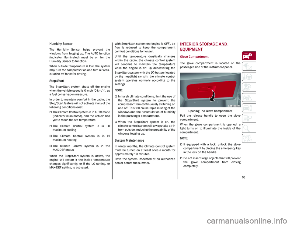
The glove compartment is located on the
passenger side of the instrument panel.
Opening The Glove Compartment
Pull the release handle to open the glove
compartment.
When the glove compartment is opened, a
light turns on to illuminate the inside of the
compartment.
NOTE:
If equipped with a lock, unlock the glove
compartment by placing the emergency key
in the lock on the handle.
Do not insert large objects that will prevent
the glove compartment from closing
completely.
21_GU_OM_EN_USC_t.book Page 55
Page 71 of 280
69
3. Instrument Cluster Display•The instrument cluster display features
a driver interactive display
Ú
page 69.
4. Fuel Gauge •The digital bar gauge shows the amount
of fuel in the tank.
• The fuel reserve/limited range
warning light turns on, a message is
displayed and there is an acoustic
signal when about 2.4 gallons (9 liters)
of fuel are left in the tank.
• The fuel pump symbol points to the
side of the vehicle where the fuel door is
located.
• P
roceeding further, the second white
notch will go off and the last one will become red, together with the indica-
tion "E" present at the bottom of the
tank. Fuel
Level Gauge
NOTE:
If the low fuel warning light switches on, refuel
at the earliest opportunity.
5. Speedometer •Indicates vehicle speed.
NOTE:
The hard telltales will illuminate for a bulb
check when the ignition is first cycled.
INSTRUMENT CLUSTER
DISPLAY
Instrument Cluster Display Description
This vehicle is equipped with a driver interac -
tive display that is located in the instrument
cluster.
When one or more of the doors have been
opened or closed and the ignition is in the OFF
position, the instrument cluster will display the
vehicle mileage for a few seconds.
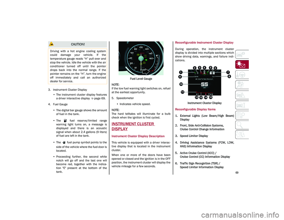
Reconfigurable Instrument Cluster Display
During operation, the instrument cluster
display is divided into multiple sections which
show driving data, warnings, and failure indi -
cations.
Instrument Cluster Display
Reconfigurable Display Items
1. External Lights (Low Beam/High Beam)Display
2. Front, Side Anti-Collision Systems, Cruise Control Change Information
3. Speed Limiter Display
4. Driving Assistance Systems (FCW, LDW, HAS) Information Display
5. Active Cruise Control (ACC) / Cruise Control (CC) Information Display
6. Traffic Sign Recognition (TSR) / Speed Limiter Information Display
CAUTION!
Driving with a hot engine cooling system
could damage your vehicle. If the
temperature gauge reads “H” pull over and
stop the vehicle. Idle the vehicle with the air
conditioner turned off until the pointer
drops back into the normal range. If the
pointer remains on the “H”, turn the engine
off immediately and call an authorized
dealer for service.
21_GU_OM_EN_USC_t.book Page 69
Page 76 of 280

GETTING TO KNOW YOUR INSTRUMENT PANEL
74
(Continued)
To access and the change the setting, turn and
push the Rotary Pad or press the desired
setting on the touchscreen.
WARNING LIGHTS AND
MESSAGES ON THE
INSTRUMENT PANEL
The following pages consist of warning lights
and messages.
NOTE:
The warning light turns on together with a
dedicated message and/or chime when
applicable. These indications are precau-
tionary and as such must not be considered
as exhaustive and/or alternative to the
information contained in the Owner’s
Manual, which you are advised to read care -
fully in all cases. Always refer to the informa -
tion in this section in the event of a failure
indication.
The failure indicators appearing on the
display are divided into two categories: very
serious and less serious faults. Serious
faults are indicated by a repeated and
prolonged warning cycle. Less serious faults
are indicated by a warning cycle with a
shorter duration. You can stop the warning
cycle in both cases by pushing the button
located on the windshield wiper stalk. The
instrument panel warning light will stay on
until the cause of the failure is eliminated.
Red Warning Lights
Air Bag Warning Light
This warning light will illuminate to
indicate a fault with the air bag, and
will turn on for four to eight seconds
as a bulb check when the ignition is
placed in the ON/RUN or ACC/ON/RUN posi -
tion. This light will illuminate with a single
chime when a fault with the air bag has been
detected, it will stay on until the fault is
cleared. If the light is either not on during
startup, stays on, or turns on while driving,
have the system inspected at an authorized
dealer as soon as possible.
Brake Warning Light
This warning light monitors various
brake functions, including brake
fluid level and parking brake applica -
tion. If the brake light turns on it may
indicate that the parking brake is applied, that
the brake fluid level is low, or that there is a
problem with the Anti-Lock Brake System
reservoir.
If the light remains on when the parking brake
has been disengaged, and the fluid level is at
the full mark on the master cylinder reservoir,
it indicates a possible brake hydraulic system
malfunction or that a problem with the Brake
Booster has been detected by the Anti-Lock
Brake System (ABS) / Electronic Stability
Control (ESC) system. In this case, the light will
remain on until the condition has been corrected. If the problem is related to the
brake booster, the ABS pump will run when
applying the brake, and a brake pedal pulsa
-
tion may be felt during each stop.
The dual brake system provides a reserve
braking capacity in the event of a failure to a
portion of the hydraulic system. A leak in either
half of the dual brake system is indicated by
the Brake Warning Light, which will turn on
when the brake fluid level in the master
cylinder has dropped below a specified level.
The light will remain on until the cause is
corrected.
NOTE:
The light may flash momentarily during sharp
cornering maneuvers, which change fluid level
conditions. The vehicle should have service
performed, and the brake fluid level checked.
If brake failure is indicated, immediate repair
is necessary.
WARNING!
The fault of the warning light is signaled by
the turning on of the icon on the instru -
ment panel. In this case, the warning light
may not indicate any faults with the
restraint systems. Before proceeding,
contact an authorized dealer to have the
system checked immediately.
21_GU_OM_EN_USC_t.book Page 74
Page 78 of 280

GETTING TO KNOW YOUR INSTRUMENT PANEL
76
required. However, the conventional brake
system will continue to operate normally if the
brake indicator light is not on.
If the ABS light is on, the brake system should
be serviced as soon as possible to restore the
benefits of Anti-Lock Brakes. If the ABS light
does not turn on when the ignition is placed in
the ON/RUN position, have the light inspected
by an authorized dealer.
Electronic Stability Control (ESC) Indicator
Light — If Equipped
When the ignition is cycled to ON, the
indicator light illuminates, but
should turn off as soon as the engine
is started.
ESC System Intervention : Intervention by the
system is indicated by the flashing of the indi -
cator light: it indicates that the vehicle is in crit -
ical stability and grip conditions.
ESC System Failure : If the indicator light does
not turn off, or if it stays on with the engine
running, a failure was found in the ESC
system.
Hill Start Assist System Failure : The illumina-
tion of the indicator light indicates a Hill Start
Assist system failure.
In these cases, contact an authorized dealer
as soon as possible.
Electronic Stability Control (ESC) OFF
Indicator Light — If Equipped
When the ignition is cycled to ON, the
indicator light illuminates, but
should turn off as soon as the engine
is started.
The indicator light illuminates to indicate that
some active safety systems have been
partially or totally deactivated
Ú
page 145.
When the active safety systems are reacti -
vated, the indicator light turns off.
Tire Pressure Low Warning Light
The indicator light will illuminate to
indicate that the tire pressure is
lower than the recommended value
and/or that slow pressure loss is
occurring. In these cases, optimal tire duration
and fuel consumption may not be guaranteed.
In any situation in which the message on the
display is “See Manual”
Ú
page 161.
Tire Pressure Monitoring System (TPMS)
Warning Light
The warning light switches on and a
message is displayed to indicate
that the tire pressure is lower than
the recommended value and/or that
slow pressure loss is occurring. In these cases,
optimal tire duration and fuel consumption
may not be guaranteed. Should one or more tires be in the condition
mentioned above, the display will show the
indications corresponding to each tire.
Each tire, including the spare (if provided),
should be checked monthly when cold and
inflated to the inflation pressure recom
-
mended by the vehicle manufacturer on the
vehicle placard or tire inflation pressure label.
If your vehicle has tires of a different size than
the size indicated on the vehicle placard or tire
inflation pressure label, you should determine
the proper tire inflation pressure for those
tires.
As an added safety feature, your vehicle has
been equipped with a TPMS that illuminates a
low tire pressure telltale when one or more of
your tires is significantly underinflated. Accord -
ingly, when the low tire pressure telltale illumi -
nates, you should stop and check your tires as
soon as possible, and inflate them to the
proper pressure. Driving on a significantly
underinflated tire causes the tire to overheat
and can lead to tire failure. Under inflation
CAUTION!
Do not continue driving with one or more
flat tires as handling may be compromised.
Stop the vehicle, avoiding sharp braking
and steering. If a tire puncture occurs,
repair immediately using the dedicated tire
repair kit and contact an authorized dealer
as soon as possible.
21_GU_OM_EN_USC_t.book Page 76