cruise control ALFA ROMEO STELVIO 2021 Owners Manual
[x] Cancel search | Manufacturer: ALFA ROMEO, Model Year: 2021, Model line: STELVIO, Model: ALFA ROMEO STELVIO 2021Pages: 280, PDF Size: 10.02 MB
Page 12 of 280
10
STARTING AND OPERATING
STARTING THE ENGINE ............................86
Starting Procedure................................. 86
Remote Starting System ....................... 86
Cold Weather Operation ........................ 87
Extended Park Starting.......................... 87
If Engine Fails To Start .......................... 87
After Starting — Warming Up The
Engine ..................................................... 88 Stopping The Engine.............................. 88
Turbocharger Cool Down ....................... 88
ENGINE BLOCK HEATER —
IF EQUIPPED .............................................89
ENGINE BREAK-IN
RECOMMENDATIONS ...............................89
Engine Break-In...................................... 89
ELECTRIC PARK BRAKE (EPB) .................90
Electric Park Brake (EPB) Operating
Modes ..................................................... 91 Safe Hold ................................................ 91
AUTOMATIC TRANSMISSION....................92
Display .................................................... 93
Gear Selector ......................................... 93
Transmission Operating Modes ............ 94
Automatic Transmission Limp Home
Mode....................................................... 96 Brake Transmission Shift Interlock
(BTSI) System ......................................... 96 Important Notes ..................................... 97
ALFA DNA SELECTOR ...............................98
Alfa DNA System .................................... 98
Driving Modes ........................................ 98
ALFA ACTIVE SUSPENSION (AAS) —
IF EQUIPPED .......................................... 101 STOP/START SYSTEM............................ 101
Operating Mode ................................... 101
System Manual Activation/
Deactivation ......................................... 102 Possible Reasons The Engine Does
Not Autostop ........................................ 102 Engine Restarting Conditions ............. 102
Safety Functions .................................. 102
Energy Saving Function....................... 102
Irregular Operation .............................. 103
Vehicle Inactivity .................................. 103
SPEED LIMITER ...................................... 103
Description ........................................... 103
Activation ............................................. 103
Speed Limit Programming .................. 103
Exceeding The Programmed Speed ... 104
Programmed Speed Icon Flashing ..... 104
Deactivation ......................................... 104
CRUISE CONTROL SYSTEMS —
IF EQUIPPED........................................... 104
Cruise Control — If Equipped .............. 104
Adaptive Cruise Control (ACC) —
If Equipped .......................................... 106
HIGHWAY ASSIST SYSTEM (HAS) —
IF EQUIPPED........................................... 114
To Activate/Deactivate........................ 114
Operation ............................................. 114
Indications On The Display ................. 115
System Status...................................... 115
Limited System Availability/
Operation ............................................. 116
TRAFFIC JAM ASSIST (TJA) SYSTEM —
IF EQUIPPED........................................... 117
To Activate/Deactivate........................ 117
Operation ............................................. 118 Indications On The Display ................. 118
System Status ..................................... 119
Limited System Availability/
Operation ............................................. 119
TRAFFIC SIGN RECOGNITION (TSR)
SYSTEM — IF EQUIPPED........................ 120
To Activate/Deactivate ....................... 120
Indications On The Display ................. 121
INTELLIGENT SPEED CONTROL (ISC)
SYSTEM — IF EQUIPPED........................ 121
To Activate/Deactivate ....................... 122
Indications On The Display ................. 122
Acceptance/Rejection Of The
Suggested Speed ................................ 122
PARKSENSE FRONT/REAR PARK ASSIST
SYSTEM — IF EQUIPPED........................ 123
ParkSense Sensors............................. 123
ParkSense Display .............................. 124
Enabling And Disabling ParkSense .... 124
ParkSense Warning Display ............... 125
Operation With A Trailer...................... 125
ParkSense System Usage
Precautions ......................................... 126
LANE DEPARTURE WARNING (LDW)
SYSTEM.................................................. 126
Lane Departure Warning Operation... 126
Turning Lane Departure Warning On
Or Off .................................................... 127 Lane Departure Warning Message .... 127
Changing Lane Departure Warning
Status................................................... 128
21_GU_OM_EN_USC_t.book Page 10
Page 18 of 280
SYMBOL GLOSSARY
16
Fuel Level Sensor
Failure
Ú
page 81
Exterior Lights Failure
Ú
page 81
Keyless System Failure
Ú
page 81
Fuel Cut-Off System Failure
Ú
page 81
Lane Departure Warning (LDW)
System Failure — If Equipped
Ú
page 81
Automatic High
Beam Headlights Failure — If Equipped
Ú
page 81
Automatic
Transmission Fluid Overheating
Ú
page 82
Audio System Failure
Ú
page 82
Amber Symbols
Speed Limiter
System Failure
Ú
page 82
Loose Fuel Filler Cap
Ú
page 82
Electric Park Brake Failure
Ú
page 82
Low Coolant Level — If Equipped
Ú
page 82
Service Adaptive
Cruise Control (ACC) System
Ú
page 82
Wear On Brake Pads
Ú
page 82
Dynamic Drive
Control System Failure
Ú
page 82
Windshield Wiper Failure
Ú
page 82
Generic Indication
Ú
page 83
Amber Symbols
All Wheel Drive
Failure
Ú
page 83
Temporary All Wheel Drive Failure — If Equipped
Ú
page 83
ABS Activation
Ú
page 83
Adaptive Front
Lighting System Failure
Ú
page 83
Soft Suspension
Calibration Insertion — If Equipped
Ú
page 83
Shock Absorbers Failure
Ú
page 83
Windshield Washer Liquid Level
Ú
page 83
Wear ON Carbon
Ceramic Material
(CCM) Brake Discs — If Equipped
Ú
page 83
Amber Symbols
21_GU_OM_EN_USC_t.book Page 16
Page 19 of 280
17
Driver Attention
Assist (DAA) System Failure
Ú
page 83
Highway Assist System (HAS)/
Traffic Jam Assist
(TJA) System Failure
Ú
page 83
Amber SymbolsGreen Symbols
Headlights
Ú
page 84
Automatic
Headlights
Ú
page 84
Stop/Start Operation
Ú
page 84
Cruise Control Activated
Ú
page 84
Adaptive Cruise Control (ACC) System — If Equipped
Ú
page 84
Blue Indicator Lights
Automatic High
Beam Headlights — If Equipped
Ú
page 84
High Beam Headlights
Ú
page 84
21_GU_OM_EN_USC_t.book Page 17
Page 71 of 280
69
3. Instrument Cluster Display•The instrument cluster display features
a driver interactive display
Ú
page 69.
4. Fuel Gauge •The digital bar gauge shows the amount
of fuel in the tank.
• The fuel reserve/limited range
warning light turns on, a message is
displayed and there is an acoustic
signal when about 2.4 gallons (9 liters)
of fuel are left in the tank.
• The fuel pump symbol points to the
side of the vehicle where the fuel door is
located.
• P
roceeding further, the second white
notch will go off and the last one will become red, together with the indica-
tion "E" present at the bottom of the
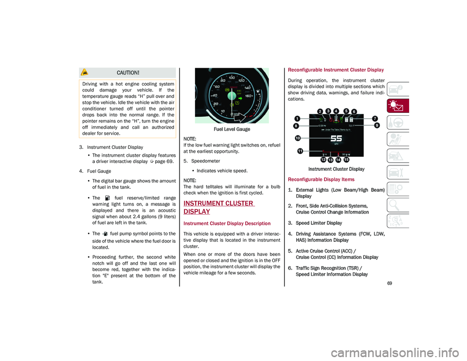
tank. Fuel
Level Gauge
NOTE:
If the low fuel warning light switches on, refuel
at the earliest opportunity.
5. Speedometer •Indicates vehicle speed.
NOTE:
The hard telltales will illuminate for a bulb
check when the ignition is first cycled.
INSTRUMENT CLUSTER
DISPLAY
Instrument Cluster Display Description
This vehicle is equipped with a driver interac -
tive display that is located in the instrument
cluster.
When one or more of the doors have been
opened or closed and the ignition is in the OFF
position, the instrument cluster will display the
vehicle mileage for a few seconds.
Reconfigurable Instrument Cluster Display
During operation, the instrument cluster
display is divided into multiple sections which
show driving data, warnings, and failure indi -
cations.
Instrument Cluster Display
Reconfigurable Display Items
1. External Lights (Low Beam/High Beam)Display
2. Front, Side Anti-Collision Systems, Cruise Control Change Information
3. Speed Limiter Display
4. Driving Assistance Systems (FCW, LDW, HAS) Information Display
5. Active Cruise Control (ACC) / Cruise Control (CC) Information Display
6. Traffic Sign Recognition (TSR) / Speed Limiter Information Display
CAUTION!
Driving with a hot engine cooling system
could damage your vehicle. If the
temperature gauge reads “H” pull over and
stop the vehicle. Idle the vehicle with the air
conditioner turned off until the pointer
drops back into the normal range. If the
pointer remains on the “H”, turn the engine
off immediately and call an authorized
dealer for service.
21_GU_OM_EN_USC_t.book Page 69
Page 84 of 280
GETTING TO KNOW YOUR INSTRUMENT PANEL
82
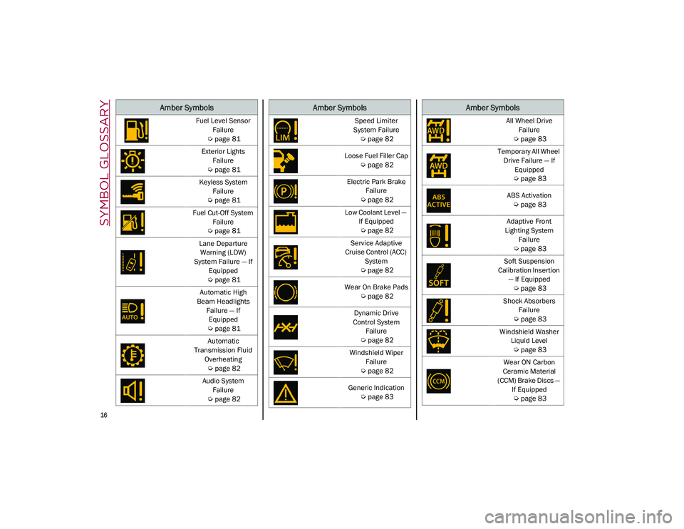
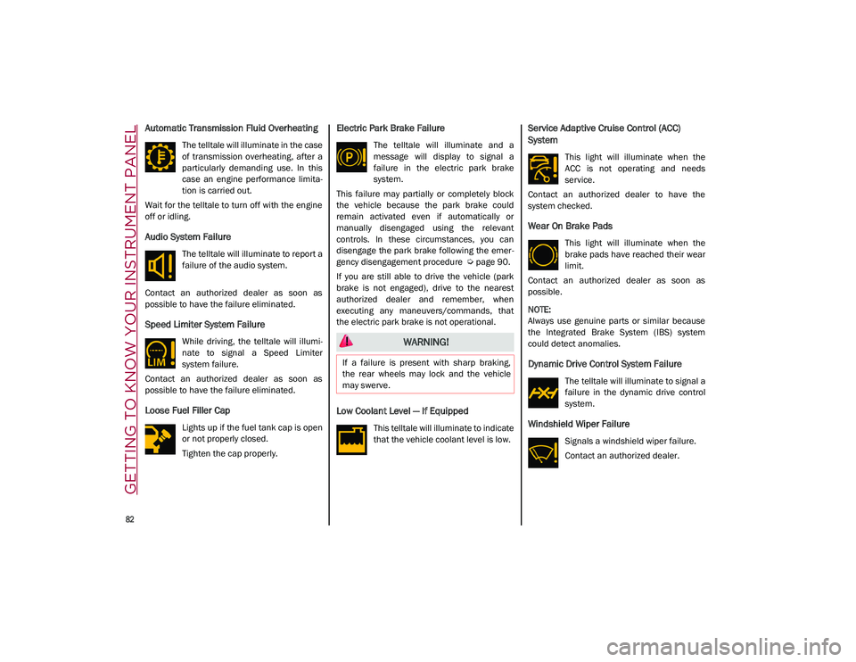
Automatic Transmission Fluid Overheating
The telltale will illuminate in the case
of transmission overheating, after a
particularly demanding use. In this
case an engine performance limita-
tion is carried out.
Wait for the telltale to turn off with the engine
off or idling.
Audio System Failure
The telltale will illuminate to report a
failure of the audio system.
Contact an authorized dealer as soon as
possible to have the failure eliminated.
Speed Limiter System Failure
While driving, the telltale will illumi -
nate to signal a Speed Limiter
system failure.
Contact an authorized dealer as soon as
possible to have the failure eliminated.
Loose Fuel Filler Cap
Lights up if the fuel tank cap is open
or not properly closed.
Tighten the cap properly.
Electric Park Brake Failure
The telltale will illuminate and a
message will display to signal a
failure in the electric park brake
system.
This failure may partially or completely block
the vehicle because the park brake could
remain activated even if automatically or
manually disengaged using the relevant
controls. In these circumstances, you can
disengage the park brake following the emer -
gency disengagement procedure
Ú
page 90.
If you are still able to drive the vehicle (park
brake is not engaged), drive to the nearest
authorized dealer and remember, when
executing any maneuvers/commands, that
the electric park brake is not operational.
Low Coolant Level — If Equipped
This telltale will illuminate to indicate
that the vehicle coolant level is low.
Service Adaptive Cruise Control (ACC)
System
This light will illuminate when the
ACC is not operating and needs
service.
Contact an authorized dealer to have the
system checked.
Wear On Brake Pads
This light will illuminate when the
brake pads have reached their wear
limit.
Contact an authorized dealer as soon as
possible.
NOTE:
Always use genuine parts or similar because
the Integrated Brake System (IBS) system
could detect anomalies.
Dynamic Drive Control System Failure
The telltale will illuminate to signal a
failure in the dynamic drive control
system.
Windshield Wiper Failure
Signals a windshield wiper failure.
Contact an authorized dealer.
WARNING!
If a failure is present with sharp braking,
the rear wheels may lock and the vehicle
may swerve.
21_GU_OM_EN_USC_t.book Page 82
Page 86 of 280
GETTING TO KNOW YOUR INSTRUMENT PANEL
84
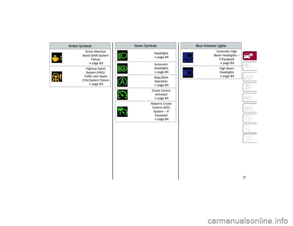
Green Symbols
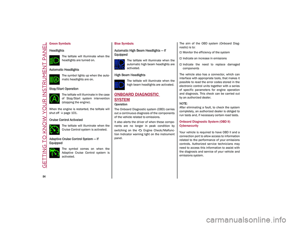
Headlights
The telltale will illuminate when the
headlights are turned on.
Automatic Headlights
The symbol lights up when the auto-
matic headlights are on.
Stop/Start Operation
The telltale will illuminate in the case
of Stop/Start system intervention
(stopping the engine).
When the engine is restarted, the telltale will
shut off
Ú
page 101.
Cruise Control Activated
The telltale will illuminate when the
Cruise Control system is activated.
Adaptive Cruise Control System — If
Equipped
The symbol comes on when the
Adaptive Cruise Control system is
activated.
Blue Symbols
Automatic High Beam Headlights — If
Equipped
The telltale will illuminate when the
automatic high beam headlights are
activated.
High Beam Headlights
The telltale will illuminate when the
high beam headlights are activated.
ONBOARD DIAGNOSTIC
SYSTEM
Operation
The Onboard Diagnostic system (OBD) carries
out a continuous diagnosis of the components
of the vehicle related to emissions.
It also alerts the driver of when these compo -
nents are no longer in peak condition by
switching on the Engine Check/Malfunc -
tion Indicator warning light on the instrument
panel. The aim of the OBD system (Onboard Diag
-
nostic) is to:
Monitor the efficiency of the system
Indicate an increase in emissions
Indicate the need to replace damaged
components
The vehicle also has a connector, which can
interface with appropriate tools, that makes it
possible to read the error codes stored in the
electronic control units together with a series
of specific parameters for engine operation
and diagnosis. This check can be carried out
by an authorized dealer.
NOTE:
After eliminating a fault, to check the system
completely, an authorized dealer is obliged to
run tests and, if necessary certain road tests.
Onboard Diagnostic System (OBD II)
Cybersecurity
Your vehicle is required to have OBD II and a
connection port to allow access to information
related to the performance of your emissions
controls. Authorized service technicians may
need to access this information to assist with
the diagnosis and service of your vehicle and
emissions system.
21_GU_OM_EN_USC_t.book Page 84
Page 105 of 280
103
Irregular Operation
In the event of malfunction, the Stop/Start
system is deactivated.
For failure indications
Ú
page 74.
Vehicle Inactivity
In the event of vehicle inactivity (or if the
battery is replaced), special attention must be
paid to the disconnection of the battery power
supply.
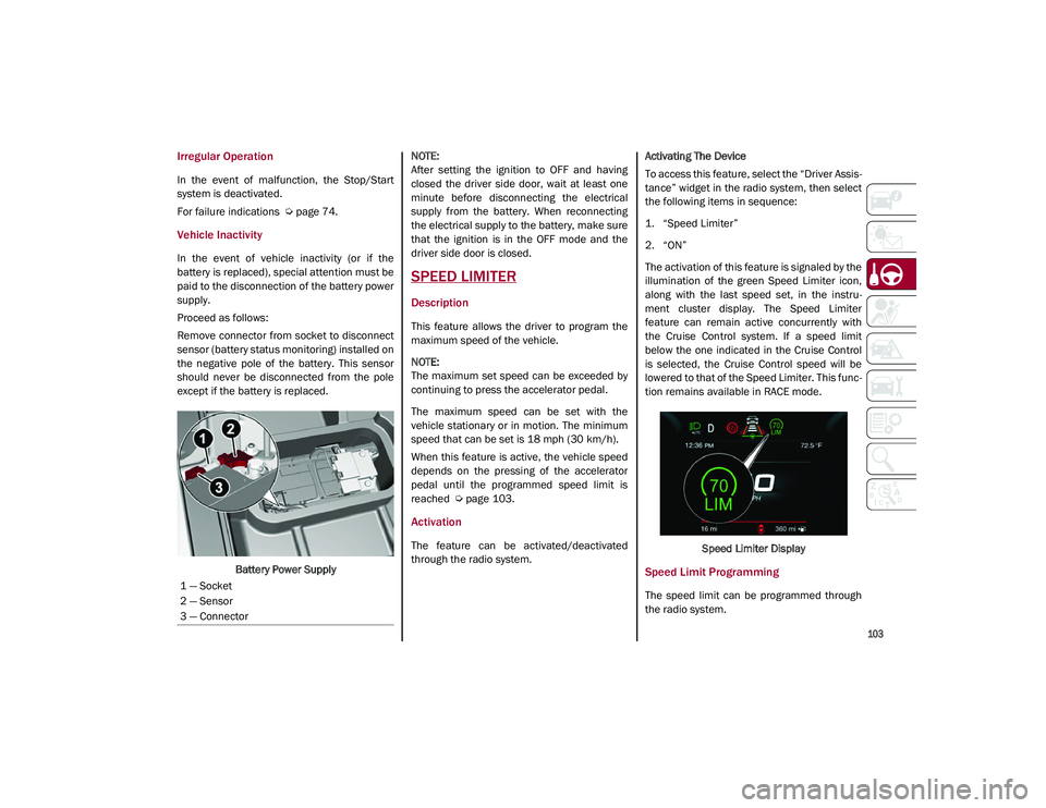
Proceed as follows:
Remove connector from socket to disconnect
sensor (battery status monitoring) installed on
the negative pole of the battery. This sensor
should never be disconnected from the pole
except if the battery is replaced.
Battery Power Supply
NOTE:
After setting the ignition to OFF and having
closed the driver side door, wait at least one
minute before disconnecting the electrical
supply from the battery. When reconnecting
the electrical supply to the battery, make sure
that the ignition is in the OFF mode and the
driver side door is closed.
SPEED LIMITER
Description
This feature allows the driver to program the
maximum speed of the vehicle.
NOTE:
The maximum set speed can be exceeded by
continuing to press the accelerator pedal.
The maximum speed can be set with the
vehicle stationary or in motion. The minimum
speed that can be set is 18 mph (30 km/h).
When this feature is active, the vehicle speed
depends on the pressing of the accelerator
pedal until the programmed speed limit is
reached
Ú
page 103.
Activation
The feature can be activated/deactivated
through the radio system. Activating The Device
To access this feature, select the “Driver Assis
-
tance” widget in the radio system, then select
the following items in sequence:
1. “Speed Limiter”
2. “ON”
The activation of this feature is signaled by the
illumination of the green Speed Limiter icon,
along with the last speed set, in the instru -
ment cluster display. The Speed Limiter
feature can remain active concurrently with
the Cruise Control system. If a speed limit
below the one indicated in the Cruise Control
is selected, the Cruise Control speed will be
lowered to that of the Speed Limiter. This func -
tion remains available in RACE mode.
Speed Limiter Display
Speed Limit Programming
The speed limit can be programmed through
the radio system.
1 — Socket
2 — Sensor
3 — Connector
21_GU_OM_EN_USC_t.book Page 103
Page 106 of 280
STARTING AND OPERATING
104
To access the function on the main menu,
select the following items in order:
1. “Driver Assistance”
2. “Speed Limiter - Set Speed”
By turning the Rotary Pad, the speed increases
by 5 mph (5 km/h), from a minimum of
18 mph (30 km/h) to a maximum of 112 mph
(180 km/h).
Exceeding The Programmed Speed
By fully pressing the accelerator pedal, the
programmed speed can be exceeded even
with the device active (e.g. in the event of over-
taking).
The device is disabled until the speed drops
below the set limit, after which it reactivates
automatically.
Programmed Speed Icon Flashing
The programmed speed will flash in the
following scenarios:
When the accelerator pedal has been fully
pressed and the vehicle has exceeded the
programmed speed.
Activating the system after setting a limit
below the effective speed of the vehicle.
In the event of overtake acceleration.
Deactivation
The feature can be activated/deactivated
through the radio system.
Deactivating The Device
To access this feature, select the “Driver Assis -
tance” widget in the radio system, then select
the following items in sequence:
1. “Speed Limiter”
2. “OFF”
Automatic Deactivation Of The Device
The device deactivates automatically in the
event of fault in the system. In this case,
contact an authorized dealer.
Temporary Signal Loss
When the devices loses the signal, the white
symbol without the speed indication illumi -
nates on the display.
System Failure
If there is a system failure, the amber symbol
illuminates on the display.
CRUISE CONTROL SYSTEMS — IF
EQUIPPED
Cruise Control — If Equipped
When engaged, the Cruise Control takes over
accelerator operations at speeds greater than
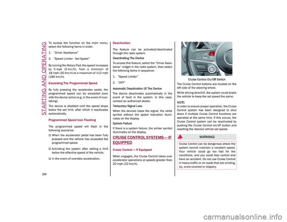
20 mph (32 km/h). Cruise Control On/Off Switch
The Cruise Control buttons are located on the
left side of the steering wheel.
While driving downhill, the system could brake
the vehicle to keep the set speed the same.
NOTE:
In order to ensure proper operation, the Cruise
Control system has been designed to shut
down if multiple Cruise Control functions are
operated at the same time. If this occurs, the
Cruise Control system can be reactivated by
pushing the Cruise Control on/off button and
resetting the desired vehicle set speed.
WARNING!
Cruise Control can be dangerous where the
system cannot maintain a constant speed.
Your vehicle could go too fast for the
conditions, and you could lose control and
have an accident. Do not use Cruise Control
in heavy traffic or on roads that are winding,
icy, snow-covered or slippery.
21_GU_OM_EN_USC_t.book Page 104
Page 107 of 280
105
To Activate
To activate the Cruise Control System, push
the on/off button located on the left side of the
steering wheel.
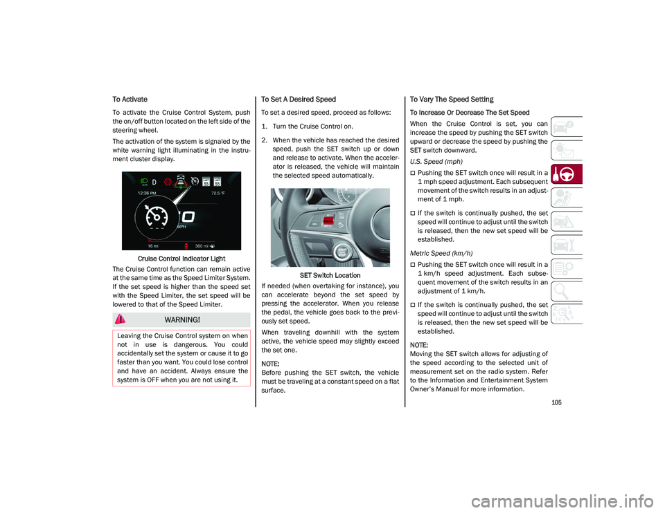
The activation of the system is signaled by the
white warning light illuminating in the instru-
ment cluster display.
Cruise Control Indicator Light
The Cruise Control function can remain active
at the same time as the Speed Limiter System.
If the set speed is higher than the speed set
with the Speed Limiter, the set speed will be
lowered to that of the Speed Limiter.
To Set A Desired Speed
To set a desired speed, proceed as follows:
1. Turn the Cruise Control on.
2. When the vehicle has reached the desired speed, push the SET switch up or down
and release to activate. When the acceler -
ator is released, the vehicle will maintain
the selected speed automatically.
SET Switch Location
If needed (when overtaking for instance), you
can accelerate beyond the set speed by
pressing the accelerator. When you release
the pedal, the vehicle goes back to the previ -
ously set speed.
When traveling downhill with the system
active, the vehicle speed may slightly exceed
the set one.
NOTE:
Before pushing the SET switch, the vehicle
must be traveling at a constant speed on a flat
surface.
To Vary The Speed Setting
To Increase Or Decrease The Set Speed
When the Cruise Control is set, you can
increase the speed by pushing the SET switch
upward or decrease the speed by pushing the
SET switch downward.
U.S. Speed (mph)
Pushing the SET switch once will result in a
1 mph speed adjustment. Each subsequent
movement of the switch results in an adjust -
ment of 1 mph.
If the switch is continually pushed, the set
speed will continue to adjust until the switch
is released, then the new set speed will be
established.
Metric Speed (km/h)
Pushing the SET switch once will result in a
1 km/h speed adjustment. Each subse -
quent movement of the switch results in an
adjustment of 1 km/h.
If the switch is continually pushed, the set
speed will continue to adjust until the switch
is released, then the new set speed will be
established.
NOTE:
Moving the SET switch allows for adjusting of
the speed according to the selected unit of
measurement set on the radio system. Refer
to the Information and Entertainment System
Owner’s Manual for more information.
WARNING!
Leaving the Cruise Control system on when
not in use is dangerous. You could
accidentally set the system or cause it to go
faster than you want. You could lose control
and have an accident. Always ensure the
system is OFF when you are not using it.
21_GU_OM_EN_USC_t.book Page 105
Page 108 of 280
STARTING AND OPERATING
106
To Accelerate For Passing
Press the accelerator as you would normally.
When the pedal is released, the vehicle will
return to the set speed.
Using Cruise Control On Hills
The transmission may downshift on hills to
maintain the vehicle set speed.
NOTE:
The Cruise Control system maintains speed up
and down hills. A slight speed change on
moderate hills is normal.
On steep hills, a greater speed loss or gain
may occur so it may be preferable to drive
without Cruise Control.
To Resume Speed
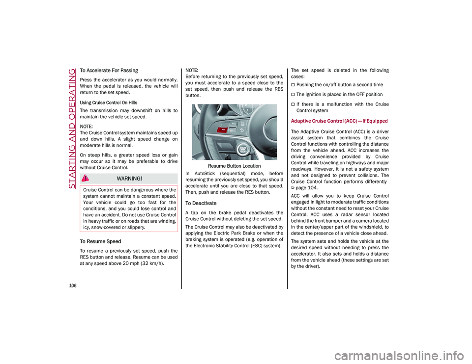
To resume a previously set speed, push the
RES button and release. Resume can be used
at any speed above 20 mph (32 km/h).
NOTE:
Before returning to the previously set speed,
you must accelerate to a speed close to the
set speed, then push and release the RES
button.
Resume Button Location
In AutoStick (sequential) mode, before
resuming the previously set speed, you should
accelerate until you are close to that speed.
Then, push and release the RES button.
To Deactivate
A tap on the brake pedal deactivates the
Cruise Control without deleting the set speed.
The Cruise Control may also be deactivated by
applying the Electric Park Brake or when the
braking system is operated (e.g. operation of
the Electronic Stability Control (ESC) system). The set speed is deleted in the following
cases:
Pushing the on/off button a second time
The ignition is placed in the OFF position
If there is a malfunction with the Cruise
Control system
Adaptive Cruise Control (ACC) — If Equipped
The Adaptive Cruise Control (ACC) is a driver
assist system that combines the Cruise
Control functions with controlling the distance
from the vehicle ahead. ACC increases the
driving convenience provided by Cruise
Control while traveling on highways and major
roadways. However, it is not a safety system
and not designed to prevent collisions. The
Cruise Control function performs differently
Ú
page 104.
ACC will allow you to keep Cruise Control
engaged in light to moderate traffic conditions
without the constant need to reset your Cruise
Control. ACC uses a radar sensor located
behind the front bumper and a camera located
in the center/upper part of the windshield, to
detect the presence of a vehicle close ahead.
The system sets and holds the vehicle at the
desired speed without needing to press the
accelerator. It also sets and holds a distance
from the vehicle ahead (these settings are set
by the driver).
WARNING!
Cruise Control can be dangerous where the
system cannot maintain a constant speed.
Your vehicle could go too fast for the
conditions, and you could lose control and
have an accident. Do not use Cruise Control
in heavy traffic or on roads that are winding,
icy, snow-covered or slippery.
21_GU_OM_EN_USC_t.book Page 106