load capacity ALFA ROMEO STELVIO 2021 Owners Manual
[x] Cancel search | Manufacturer: ALFA ROMEO, Model Year: 2021, Model line: STELVIO, Model: ALFA ROMEO STELVIO 2021Pages: 280, PDF Size: 10.02 MB
Page 13 of 280
11
LANE KEEPING ASSIST (LKA)
SYSTEM —IF EQUIPPED......................... 128
Turning Lane Keeping Assist On Or
Off ......................................................... 129 Lane Keeping Assist Warning
Message ...............................................129
REAR BACK UP CAMERA / DYNAMIC
GRIDLINES ............................................. 132 REFUELING THE VEHICLE ..................... 133
Refueling The Vehicle ..........................133
Refueling Capacity ............................... 133
Refueling Procedure ...........................133
VEHICLE LOADING ................................. 135
Certification Label................................ 135
TRAILER TOWING................................... 136
Common Towing Definitions ...............137
Trailer Hitch Classification .................. 137
Trailer Towing Weights (Maximum
Trailer Weight Ratings) .....................138 Trailer And Tongue Weight ................. 138
Towing Requirements..........................139
Towing Tips ..........................................141
Installing The Receiver ........................ 141
Connecting The Electrical System ......141
Removing The Receiver ....................... 142
SUGGESTIONS FOR DRIVING................ 142
Saving Fuel ...........................................142
Driving Style .........................................142
Conditions Of Use ................................ 142
Performance — Quadrifoglio ...............143
SAFETY
ACTIVE SAFETY SYSTEMS...................... 145
Anti-Lock Brake System (ABS) ........... 145
Active Torque Vectoring (ATV)
System — If Equipped .......................... 145 Dynamic Steering Torque (DST)
System ................................................. 146 Drive Train Control (DTC) System ....... 146
Electronic Stability Control (ESC)
System ................................................. 146 Hill Descent Control (HDC) System —
If Equipped ........................................... 147 Hill Start Assist (HSA) System ............. 148
Panic Brake Assist (PBA) System ....... 149
Traction Control System (TCS) ............ 149
AUXILIARY DRIVING SYSTEMS .............. 149
Blind Spot Monitoring (BSM) System —
If Equipped ......................................... 150 Active Blind Spot Assist (ABSA)
System — If Equipped ......................... 152 Driver Attention Assist (DAA)
System — If Equipped .......................... 155 Forward Collision Warning Plus (FCW+)
System — If Equipped ......................... 156 Tire Pressure Monitoring System
(TPMS) .................................................. 161
OCCUPANT RESTRAINT SYSTEMS ........ 163
Occupant Restraint Systems
Features .............................................. 163 Important Safety Precautions ............ 163
Seat Belt Systems .............................. 164
Supplemental Restraint Systems
(SRS) .................................................... 169 Child Restraints ................................. 178
SAFETY TIPS .......................................... 188
Transporting Passengers .................... 188
Transporting Pets ............................. 189
Safety Checks You Should Make
Inside The Vehicle .............................. 189 Periodic Safety Checks You Should
Make Outside The Vehicle .................. 190 Exhaust Gas ..................................... 190
Carbon Monoxide Warnings ............. 191
IN CASE OF EMERGENCY
HAZARD WARNING FLASHERS ............. 192
SOS — EMERGENCY CALL ..................... 192
JACKING AND TIRE CHANGING............. 195
General Instructions ........................... 195
Jack Information And Usage
Precautions ......................................... 195 Changing Procedure ........................... 196
TIRE SERVICE KIT — IF EQUIPPED ........ 198
Description .......................................... 198
Inflation Procedure ............................. 199
Checking And Restoring Tire
Pressure............................................... 201
21_GU_OM_EN_USC_t.book Page 11
Page 138 of 280
STARTING AND OPERATING
136
Gross Vehicle Weight Rating (GVWR)
The GVWR is the total permissible weight of
your vehicle including driver, passengers,
vehicle, options and cargo. The label also
specifies maximum capacities of front and
rear axle systems (GAWR). Total load must be
limited so GVWR and front and rear GAWR are
not exceeded.
Payload
The payload of a vehicle is defined as the
allowable load weight a truck can carry,
including the weight of the driver, all passen-
gers, options and cargo.
Gross Axle Weight Rating (GAWR)
The GAWR is the maximum permissible load
on the front and rear axles. The load must be
distributed in the cargo area so that the GAWR
of each axle is not exceeded.
Each axle GAWR is determined by the compo -
nents in the system with the lowest load
carrying capacity (axle, springs, tires or
wheels). Heavier axles or suspension compo -
nents sometimes specified by purchasers for
increased durability do not necessarily
increase the vehicle's GVWR.
Tire Size
The tire size on the Vehicle Certification Label
represents the actual tire size on your vehicle.
Replacement tires must be equal to the load
capacity of this tire size.
Rim Size
This is the rim size that is appropriate for the
tire size listed.
Inflation Pressure
This is the cold tire inflation pressure for your
vehicle for all loading conditions up to full
GAWR.
Curb Weight
The curb weight of a vehicle is defined as the
total weight of the vehicle with all fluids,
including vehicle fuel, at full capacity condi -
tions, and with no occupants or cargo loaded
into the vehicle. The front and rear curb weight
values are determined by weighing your
vehicle on a commercial scale before any
occupants or cargo are added.
Loading
The actual total weight and the weight of the
front and rear of your vehicle at the ground can
best be determined by weighing it when it is
loaded and ready for operation.
The entire vehicle should first be weighed on a
commercial scale to ensure that the GVWR
has not been exceeded. The weight on the
front and rear of the vehicle should then be
determined separately to be sure that the load
is properly distributed over the front and rear
axle. Weighing the vehicle may show that the
GAWR of either the front or rear axles has
been exceeded but the total load is within the specified GVWR. If so, weight must be shifted
from front to rear or rear to front as appro
-
priate until the specified weight limitations are
met. Store the heavier items down low and be
sure that the weight is distributed equally.
Stow all loose items securely before driving.
Improper weight distributions can have an
adverse effect on the way your vehicle steers
and handles and the way the brakes operate.
TRAILER TOWING
In this section you will find safety tips and
information on limits to the type of towing you
can reasonably do with your vehicle. Before
towing a trailer, carefully review this informa -
tion to tow your load as efficiently and safely
as possible.
To maintain the New Vehicle Limited Warranty
coverage, follow the requirements and recom -
mendations in this manual concerning vehi -
cles used for trailer towing.
CAUTION!
Do not load your vehicle any heavier than
the GVWR or the maximum front and rear
GAWR. If you do, parts on your vehicle can
break, or it can change the way your vehicle
handles. This could cause you to lose
control. Also overloading can shorten the
life of your vehicle.
21_GU_OM_EN_USC_t.book Page 136
Page 139 of 280
137
Common Towing Definitions
The following trailer towing related definitions
will assist you in understanding the following
information:
Gross Vehicle Weight Rating (GVWR)
The GVWR is the total allowable weight of your
vehicle. This includes driver, passengers,
cargo and tongue weight. The total load must
be limited so that you do not exceed the GVWR
Ú
page 135.
Gross Trailer Weight (GTW)
The GTW is the weight of the trailer plus the
weight of all cargo, consumables, and equip -
ment (permanent or temporary) loaded in or
on the trailer in its "loaded and ready for oper -
ation" condition.
The recommended way to measure GTW is to
put your fully loaded trailer on a vehicle scale.
The entire weight of the trailer must be
supported by the scale.
Gross Combination Weight Rating (GCWR)
The GCWR is the total allowable weight of your
vehicle and trailer when weighed in combination.
Gross Axle Weight Rating (GAWR)
The GAWR is the maximum capacity of the
front and rear axles. Distribute the load over
the front and rear axles evenly. Make sure that
you do not exceed either front or rear GAWR
Ú
page 135.
Tongue Weight (TW)
The tongue weight is the downward force
exerted on the hitch ball by the trailer. You
must consider this as part of the load on your
vehicle.
Trailer Frontal Area
The frontal area is the maximum height multi -
plied by the maximum width of the front of a
trailer.
Weight-Carrying Hitch
A weight-carrying hitch supports the trailer
tongue weight, just as if it were luggage
located at a hitch ball or some other
connecting point of the vehicle. These kinds of
hitches are the most popular on the market
today and they are commonly used to tow
small and medium sized trailers.
Weight-Distributing Hitch
A weight-distributing system works by applying
leverage through spring (load) bars. They are
typically used for heavier loads to distribute
trailer tongue weight to the tow vehicle's front axle and the trailer axle(s). When used in
accordance with the manufacturer's direc
-
tions, it provides for a more level ride, offering
more consistent steering and brake control
thereby enhancing towing safety. The addition
of a friction/hydraulic sway control also
dampens sway caused by traffic and cross -
winds and contributes positively to tow vehicle
and trailer stability. Trailer Sway Control and a
weight distributing (load equalizing) hitch are
recommended for heavier Tongue Weights
(TW) and may be required depending on
vehicle and trailer configuration/loading to
comply with Gross Axle Weight Rating (GAWR)
requirements.
Trailer Hitch Classification
The following chart provides the industry stan -
dard for the maximum trailer weight a given
trailer hitch class can tow and should be used
to assist you in selecting the correct trailer
hitch for your intended towing condition.
WARNING!
It is important that you do not exceed the
maximum front or rear GAWR. A dangerous
driving condition can result if either rating is
exceeded. You could lose control of the
vehicle and have a collision.
WARNING!
An improperly adjusted Weight Distrib -
uting Hitch system may reduce handling,
stability, braking performance, and could
result in a collision.
Weight Distributing Systems may not be
compatible with Surge Brake Couplers.
Consult with the hitch and trailer manu -
facturer or a reputable Recreational
Vehicle dealer for additional information.
21_GU_OM_EN_USC_t.book Page 137
Page 141 of 280
139
(Continued)
Consider the following items when computing
the weight on the rear axle of the vehicle:
The tongue weight of the trailer.
The weight of any other type of cargo or
equipment put in or on your vehicle.
The weight of the driver and all passengers.
NOTE:
Remember that everything put into or on the
trailer adds to the load on your vehicle. Also,
additional factory-installed options or
dealer-installed options must be considered
as part of the total load on your vehicle. Refer
to the “Tire And Loading Information” placard
for the maximum combined weight of occu -
pants and cargo for your vehicle.
Towing Requirements
To promote proper break-in of your new
vehicle drivetrain components, the following
guidelines are recommended:
Towing Requirements — Tires
Do not attempt to tow a trailer while using a
compact spare tire.
Do not drive more than 50 mph (80 km/h)
when towing while using a full size spare
tire.
Proper tire inflation pressures are essential
to the safe and satisfactory operation of
your vehicle.
Check the trailer tires for proper tire infla -
tion pressures before trailer usage.
Check for signs of tire wear or visible tire
damage before towing a trailer.
Replacing tires with a higher load carrying
capacity will not increase the vehicle's
GVWR and GAWR limits.
For proper tire inflation procedures
Ú
page 233.
WARNING!
Improper towing can lead to a collision.
Follow these guidelines to make your trailer
towing as safe as possible:
Make certain that the load is secured in
the trailer and that it will not shift during
travel. When trailering cargo that is not
fully secured, dynamic load shifts can
occur that may be difficult for the driver to
control. You could lose control of your
vehicle and have a collision.
When hauling cargo, or towing a trailer, do
not overload your vehicle or trailer. Over -
loading can cause a loss of control, poor
performance, or damage to brakes, axle,
engine, transmission, steering, suspen -
sion, chassis structure, or tires.
Safety chains must always be used
between your vehicle and trailer. Always
connect the chains to the frame or hook
retainers of the vehicle hitch. Cross the
chains under the trailer tongue and allow
enough slack for turning corners.
Vehicles with trailers should not be parked
on a grade. When parking, apply the
parking brake on the tow vehicle. Put the
tow vehicle transmission in PARK. Always
block or "chock" the trailer wheels.
GCWR must not be exceeded.
Total weight must be distributed between
the tow vehicle and the trailer such that
the following four ratings are not
exceeded:
• GVWR
• GTW
• GAWR
• Tongue weight rating for the trailer
hitch utilized.
WARNING! (Continued) CAUTION!
Do not tow a trailer at all during the first
500 miles (805 km) the new vehicle is
driven. The engine, axle or other parts
could be damaged.
Then, during the first 500 miles (805 km)
that a trailer is towed, do not drive over
50 mph (80 km/h) and do not make
starts at full throttle. This helps the engine
and other parts of the vehicle wear in at
the heavier loads.
21_GU_OM_EN_USC_t.book Page 139
Page 142 of 280
STARTING AND OPERATING
140
Towing Requirements — Trailer Brakes
Do not interconnect the hydraulic brake
system or vacuum system of your vehicle
with that of the trailer. This could cause
inadequate braking and possible personal
injury.
An electronically actuated trailer brake
controller is required when towing a trailer
with electronically actuated brakes. When
towing a trailer equipped with a hydraulic
surge actuated brake system, an electronic
brake controller is not required.
Trailer brakes are recommended for trailers
over 1,000 lbs (453 kg) and required for
trailers in excess of 2,000 lbs (907 kg).
Towing Requirements — Trailer Lights And
Wiring
Whenever you pull a trailer, regardless of the
trailer size, stoplights and turn signals on the
trailer are required for motoring safety.
The Trailer Tow Package may include a four-
and seven-pin wiring harness. Use a factory
approved trailer harness and connector.
NOTE:
Do not cut or splice wiring into the vehicle’s
wiring harness.
The electrical connections are all complete to
the vehicle but you must mate the harness to
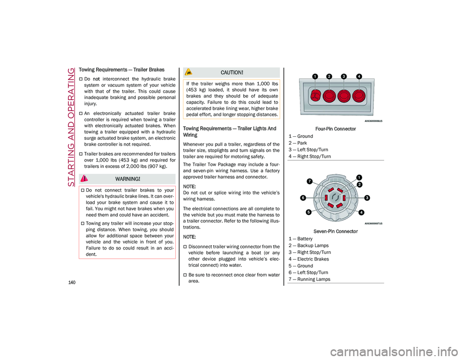
a trailer connector. Refer to the following illus -
trations.
NOTE:
Disconnect trailer wiring connector from the
vehicle before launching a boat (or any
other device plugged into vehicle’s elec -
trical connect) into water.
Be sure to reconnect once clear from water
area. Four-Pin Connector
Seven-Pin Connector
WARNING!
Do not connect trailer brakes to your
vehicle's hydraulic brake lines. It can over -
load your brake system and cause it to
fail. You might not have brakes when you
need them and could have an accident.
Towing any trailer will increase your stop -
ping distance. When towing, you should
allow for additional space between your
vehicle and the vehicle in front of you.
Failure to do so could result in an acci -
dent.
CAUTION!
If the trailer weighs more than 1,000 lbs
(453 kg) loaded, it should have its own
brakes and they should be of adequate
capacity. Failure to do this could lead to
accelerated brake lining wear, higher brake
pedal effort, and longer stopping distances.
1 — Ground
2 — Park
3 — Left Stop/Turn
4 — Right Stop/Turn
1 — Battery
2 — Backup Lamps
3 — Right Stop/Turn
4 — Electric Brakes
5 — Ground
6 — Left Stop/Turn
7 — Running Lamps
21_GU_OM_EN_USC_t.book Page 140
Page 145 of 280
143
Traffic And Road Conditions
High fuel consumption is caused by heavy
traffic, for instance when traveling in traffic
with frequent use of low gears or in cities with
many traffic lights. Winding mountain roads
and rough road surfaces also adversely affect
consumption.
Stops In Traffic
During prolonged stops (e.g. railway cross-
ings), turn off the engine.
Performance — Quadrifoglio
This vehicle is equipped with an engine
capable of delivering exceptionally fast accel -
eration and speed:
Peak power: 505 HP at 6,500 RPM.
Peak torque: 443 ft-lbs at 2,500–5,000 RPM.
Top speed: 176 mph (283 km/h).
Acceleration from 0 to 60 mph (0 to 100 km/h):
3.6 seconds.
For safe driving, it is essential, particularly
during the first days of use, to get to know the
car by driving carefully and gradually discov -
ering its performance.
Brakes
The car braking system may be available with
four carbon-ceramic material brake discs, one
on each wheel. In order to guarantee the maximum braking
capacity for the first use, Alfa Romeo performs
a "run-in" procedure for discs and pads directly
at the factory.
The use of carbon-ceramic material brake
discs guarantees braking features (better
deceleration/pedal load ratio, braking
distances, fading resistance) proportional to
the dynamic features of the car in addition to
considerably decreasing the unsprung compo
-
nent weight.
The materials used and the structural features
of the system could generate unusual noises
which have absolutely no adverse effect on
correct operation and reliability of the braking
system.
Greater pressure may need to be applied to
the brake pedal the first time to keep the same
braking capacities in presence of condensa -
tion or salt on the braking surfaces, for
example after washing or if the car is not used
for a long time.
NOTE:
Given the high technological level of this
system, any servicing on it must be performed
by an authorized dealer which exclusively has
the skills needed for the repair and mainte -
nance operations. In case of intensive, high-performance use of
the car, have the efficiency of the
carbon-ceramic material braking system
inspected as shown on the Maintenance Plan
at an authorized dealer.
Driving On Race Tracks
Before driving on a track using a racing style, it
is necessary to:
Attend a race track driving course.
Check the liquid levels in the engine
compartment
Ú
page 208.
Have the car inspected at an authorized
dealer.
Remember that the car was not designed to be
driven exclusively on the race track and that
this use increases stress and component
wear.
NOTE:
Quadrifoglio front brakes are equipped with
Non-Asbestos Organic (NAO) type pads. These
pads are NOT suitable for high thermal loads
(for example track use). If you want to use
vehicle on a track it is recommended to use
the optional CCM Brakes (Carbon Ceramic
Brake disc).
21_GU_OM_EN_USC_t.book Page 143
Page 151 of 280
149
Panic Brake Assist (PBA) System
The PBA system is designed to improve the
vehicle’s braking capacity during emergency
braking.
The system detects emergency braking by
monitoring the speed and force with which the
brake pedal is pressed, and consequently
applies the optimal brake pressure. This can
reduce the braking distance: the PBA system
therefore complements the ABS.
Maximum assistance from the PBA system is
obtained by pressing the brake pedal very
quickly. In addition, the brake pedal should be
pressed continuously during braking, avoiding
intermittent presses, to get the most out of thesystem. Do not reduce pressure on the brake
pedal until braking is no longer necessary.
The PBA system is deactivated when the brake
pedal is released.Traction Control System (TCS)
The TCS automatically operates in the event of
slipping, loss of grip on wet roads (hydro
-
planing), and acceleration on one or both drive
wheels on roads that are slippery, snowy, icy,
etc. Depending on the slipping conditions, two
different control systems are activated:
If the slipping involves both drive wheels,
the system intervenes, reducing the power
transmitted by the engine.
If the slipping only involves one of the drive
wheels, the Brake Limited Differential (BLD)
function is activated, automatically braking the wheel which is slipping (the behavior of
a self-locking differential is simulated). This
will increase the engine torque transferred
to the wheel which isn't slipping.
System Intervention
The intervention of the system is indicated by
the flashing of the ESC warning light on the
instrument panel, to inform the driver that the
vehicle stability and grip are critical.
AUXILIARY DRIVING SYSTEMS
The following auxiliary driving systems are
available in this vehicle:
Blind Spot Monitoring (BSM) — if equipped
Active Blind Spot Assist (ABSA) — if
equipped
Forward Collision Warning Plus (FCW+)
Tire Pressure Monitoring System (TPMS)
The vehicle may also be fitted with the
following driving assistance systems:
Driver Attention Assist (DAA)
Lane Departure Warning (LDW)
Lane Keeping Assist (LKA)
Highway Assist System (HAS)
Traffic Jam Assist (TJA)
Adaptive Cruise Control (ACC)
Intelligent Speed Control (ISC)
Traffic Sign Recognition (TSR)
WARNING!
There may be situations where the Hill Start
Assist (HSA) will not activate and slight
rolling may occur, such as on minor hills or
with a loaded vehicle, or while pulling a
trailer. HSA is not a substitute for active
driving involvement. It is always the driver’s
responsibility to be attentive to distance to
other vehicles, people, and objects, and
most importantly brake operation to ensure
safe operation of the vehicle under all road
conditions. Your complete attention is
always required while driving to maintain
safe control of your vehicle. Failure to follow
these warnings can result in a collision or
serious personal injury.
WARNING!
The Panic Brake Assist (PBA) cannot
prevent the natural laws of physics from
acting on the vehicle, nor can it increase
the traction afforded by prevailing road
conditions. PBA cannot prevent collisions,
including those resulting from excessive
speed in turns, driving on very slippery
surfaces, or hydroplaning. The capabilities
of a PBA-equipped vehicle must never be
exploited in a reckless or dangerous
manner, which could jeopardize the user's
safety or the safety of others.
21_GU_OM_EN_USC_t.book Page 149
Page 239 of 280
237
Tire Loading And Tire Pressure
NOTE:
The proper cold tire inflation pressure is listed
on the driver’s side B-pillar or the rear edge of
the driver's side door.
Check the inflation pressure of each tire,
including the spare tire (if equipped), at least
monthly and inflate to the recommended pres-
sure for your vehicle.
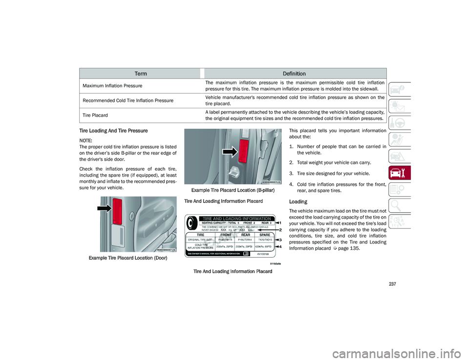
Example Tire Placard Location (Door) Example Tire Placard Location (B-pillar)
Tire And Loading Information Placard
Tire And Loading Information Placard This placard tells you important information
about the:
1. Number of people that can be carried in
the vehicle.
2. Total weight your vehicle can carry.
3. Tire size designed for your vehicle.
4. Cold tire inflation pressures for the front, rear, and spare tires.
Loading
The vehicle maximum load on the tire must not
exceed the load carrying capacity of the tire on
your vehicle. You will not exceed the tire's load
carrying capacity if you adhere to the loading
conditions, tire size, and cold tire inflation
pressures specified on the Tire and Loading
Information placard
Ú
page 135.
Maximum Inflation Pressure
The maximum inflation pressure is the maximum permissible cold tire inflation
pressure for this tire. The maximum inflation pressure is molded into the sidewall.
Recommended Cold Tire Inflation Pressure Vehicle manufacturer's recommended cold tire inflation pressure as shown on the
tire placard.
Tire Placard A label permanently attached to the vehicle describing the vehicle’s loading capacity,
the original equipment tire sizes and the recommended cold tire inflation pressures.
TermDefinition
21_GU_OM_EN_USC_t.book Page 237
Page 240 of 280
SERVICING AND MAINTENANCE
238
NOTE:
Under a maximum loaded vehicle condition,
gross axle weight ratings (GAWRs) for the front
and rear axles must not be exceeded. For
further information on GAWRs, vehicle
loading, and trailer towing
Ú
page 135.
To determine the maximum loading conditions
of your vehicle, locate the statement “The
combined weight of occupants and cargo
should never exceed XXX kg or XXX lbs” on the
Tire and Loading Information placard. The
combined weight of occupants, cargo/luggage
and trailer tongue weight (if applicable) should
never exceed the weight referenced here.
Steps For Determining Correct Load
Limit—
(1) Locate the statement “The
combined weight of occupants and
cargo should never exceed XXX kg or
XXX lbs.” on your vehicle's placard.
(2) Determine the combined weight of
the driver and passengers that will be
riding in your vehicle.
(3) Subtract the combined weight of the
driver and passengers from XXX kg or
XXX lbs. (4) The resulting figure equals the avail
-
able amount of cargo and luggage load
capacity. For example, if “XXX” amount
equals 1400 lbs. and there will be five
150 lb passengers in your vehicle, the
amount of available cargo and luggage
load capacity is 650 lbs. (1400-750
(5x150) = 650 lbs.).
(5) Determine the combined weight of
luggage and cargo being loaded on the
vehicle. That weight may not safely
exceed the available cargo and luggage
load capacity calculated in Step 4.
(6) If your vehicle will be towing a trailer,
load from your trailer will be transferred
to your vehicle. Consult this manual to
determine how this reduces the avail -
able cargo and luggage load capacity of
your vehicle.
Metric Example For Load Limit
For example, if “XXX” amount equals 635 kg
and there will be five 68 kg passengers in your
vehicle, the amount of available cargo and
luggage load capacity is 295 kg (635-340
(5x68) = 295 kg) as shown in step 4.
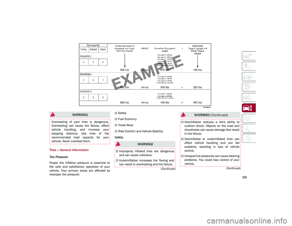
NOTE:
If your vehicle will be towing a trailer, load
from your trailer will be transferred to your
vehicle. The following table shows examples
on how to calculate total load, cargo/
luggage, and towing capacities of your
vehicle with varying seating configurations
and number and size of occupants. This
table is for illustration purposes only and
may not be accurate for the seating and
load carry capacity of your vehicle.
For the following example, the combined
weight of occupants and cargo should never
exceed 865 lbs (392 kg).
21_GU_OM_EN_USC_t.book Page 238
Page 241 of 280
239
(Continued)
(Conti n
ued)
Tires — General Information
Tire Pressure
Proper tire inflation pressure is essential to
the safe and satisfactory operation of your
vehicle. Four primary areas are affected by
improper tire pressure:
Safety
Fuel Economy
Tread Wear
Ride Comfort and Vehicle Stability
Safety
WARNING!
Overloading of your tires is dangerous.
Overloading can cause tire failure, affect
vehicle handling, and increase your
stopping distance. Use tires of the
recommended load capacity for your
vehicle. Never overload them.
WARNING!
Improperly inflated tires are dangerous
and can cause collisions.
Underinflation increases tire flexing and
can result in overheating and tire failure.
Overinflation reduces a tire's ability to
cushion shock. Objects on the road and
chuckholes can cause damage that result
in tire failure.
Overinflated or underinflated tires can
affect vehicle handling and can fail
suddenly, resulting in loss of vehicle
control.
Unequal tire pressures can cause steering
problems. You could lose control of your
vehicle.
WARNING! (Continued)
21_GU_OM_EN_USC_t.book Page 239