tire pressure ALFA ROMEO STELVIO 2021 Owners Manual
[x] Cancel search | Manufacturer: ALFA ROMEO, Model Year: 2021, Model line: STELVIO, Model: ALFA ROMEO STELVIO 2021Pages: 280, PDF Size: 10.02 MB
Page 13 of 280
11
LANE KEEPING ASSIST (LKA)
SYSTEM —IF EQUIPPED......................... 128
Turning Lane Keeping Assist On Or
Off ......................................................... 129 Lane Keeping Assist Warning
Message ...............................................129
REAR BACK UP CAMERA / DYNAMIC
GRIDLINES ............................................. 132 REFUELING THE VEHICLE ..................... 133
Refueling The Vehicle ..........................133
Refueling Capacity ............................... 133
Refueling Procedure ...........................133
VEHICLE LOADING ................................. 135
Certification Label................................ 135
TRAILER TOWING................................... 136
Common Towing Definitions ...............137
Trailer Hitch Classification .................. 137
Trailer Towing Weights (Maximum
Trailer Weight Ratings) .....................138 Trailer And Tongue Weight ................. 138
Towing Requirements..........................139
Towing Tips ..........................................141
Installing The Receiver ........................ 141
Connecting The Electrical System ......141
Removing The Receiver ....................... 142
SUGGESTIONS FOR DRIVING................ 142
Saving Fuel ...........................................142
Driving Style .........................................142
Conditions Of Use ................................ 142
Performance — Quadrifoglio ...............143
SAFETY
ACTIVE SAFETY SYSTEMS...................... 145
Anti-Lock Brake System (ABS) ........... 145
Active Torque Vectoring (ATV)
System — If Equipped .......................... 145 Dynamic Steering Torque (DST)
System ................................................. 146 Drive Train Control (DTC) System ....... 146
Electronic Stability Control (ESC)
System ................................................. 146 Hill Descent Control (HDC) System —
If Equipped ........................................... 147 Hill Start Assist (HSA) System ............. 148
Panic Brake Assist (PBA) System ....... 149
Traction Control System (TCS) ............ 149
AUXILIARY DRIVING SYSTEMS .............. 149
Blind Spot Monitoring (BSM) System —
If Equipped ......................................... 150 Active Blind Spot Assist (ABSA)
System — If Equipped ......................... 152 Driver Attention Assist (DAA)
System — If Equipped .......................... 155 Forward Collision Warning Plus (FCW+)
System — If Equipped ......................... 156 Tire Pressure Monitoring System
(TPMS) .................................................. 161
OCCUPANT RESTRAINT SYSTEMS ........ 163
Occupant Restraint Systems
Features .............................................. 163 Important Safety Precautions ............ 163
Seat Belt Systems .............................. 164
Supplemental Restraint Systems
(SRS) .................................................... 169 Child Restraints ................................. 178
SAFETY TIPS .......................................... 188
Transporting Passengers .................... 188
Transporting Pets ............................. 189
Safety Checks You Should Make
Inside The Vehicle .............................. 189 Periodic Safety Checks You Should
Make Outside The Vehicle .................. 190 Exhaust Gas ..................................... 190
Carbon Monoxide Warnings ............. 191
IN CASE OF EMERGENCY
HAZARD WARNING FLASHERS ............. 192
SOS — EMERGENCY CALL ..................... 192
JACKING AND TIRE CHANGING............. 195
General Instructions ........................... 195
Jack Information And Usage
Precautions ......................................... 195 Changing Procedure ........................... 196
TIRE SERVICE KIT — IF EQUIPPED ........ 198
Description .......................................... 198
Inflation Procedure ............................. 199
Checking And Restoring Tire
Pressure............................................... 201
21_GU_OM_EN_USC_t.book Page 11
Page 14 of 280
12
JUMP STARTING .................................... 201
Remote Battery Connection Posts......202
Jump Starting Procedure.....................203
Bump Starting ..................................204
ENGINE OVERHEATING ......................... 204 MANUAL PARK RELEASE ...................... 205TOWING A DISABLED VEHICLE ............. 205
Four-Wheel Drive (AWD) Models .........206
TOW EYES .............................................. 206
ENHANCED ACCIDENT RESPONSE
SYSTEM (EARS) ..................................... 207EVENT DATA RECORDER (EDR) ............ 207
SERVICING AND MAINTENANCE
SCHEDULED SERVICING ....................... 208
Periodic Checks ...................................208
Heavy Usage Of The Vehicle ...............208
Maintenance Plan (2.0L Engine) ........209
Maintenance Plan (2.9L Engine) ........212
ENGINE COMPARTMENT....................... 214
Checking Levels — 2.0L Engine .......... 214
Checking Levels — 2.9L Engine .......... 215
Engine Oil ............................................. 215
Engine Coolant Fluid............................216
Washer Fluid For Windshield/
Headlights ............................................ 217 Brake Fluid ...........................................217
Automatic Transmission Activation
System Oil ............................................ 217 Useful Advice For Extending The Life Of
Your Battery..........................................217 Battery ..................................................217
Pressure Washing ................................ 218
BATTERY RECHARGING ......................... 218
Important Notes .................................. 218
VEHICLE MAINTENANCE ........................ 219
Engine Oil ............................................. 219
Engine Oil Filter ................................... 220
Engine Air Cleaner Filter ..................... 220
Air Conditioning System
Maintenance........................................ 220 Lubricating Moving Parts Of The
Bodywork ............................................. 220 Windshield Wiper................................. 221
Exhaust System ................................... 222
Cooling System .................................... 223
Braking System.................................... 224
Automatic Transmission ..................... 225
Replacing The Battery ......................... 225
Fuses .................................................... 225
Bulb Replacement ............................... 229
TIRES ...................................................... 233
Tire Safety Information .................... 233
Tires — General Information .............. 239
Spare Tires — If Equipped .................. 244
Wheel And Wheel Trim Care ............ 245
Tire Types ............................................. 246
Tire Chains and Traction Devices ....... 247
Tire Rotation Recommendations........ 247
DEPARTMENT OF TRANSPORTATION
UNIFORM TIRE QUALITY GRADES ......... 248
Treadwear ............................................ 248
Traction Grades ................................... 248
Temperature Grades ........................... 248
STORING THE VEHICLE ......................... 249 BODYWORK ........................................... 249
Protection Against Atmospheric
Agents .................................................. 249 Corrosion Warranty ............................. 250
Preserving The Bodywork .................. 250
INTERIORS ............................................. 251
Seats And Fabric Parts ....................... 251
Leather Seats ...................................... 251
Plastic And Coated Parts .................... 251
Alcantara Parts — If Equipped ............ 251
Genuine Leather Parts........................ 251
Carbon Fiber Parts .............................. 252
TECHNICAL SPECIFICATIONS
VEHICLE IDENTIFICATION
NUMBER (VIN) ....................................... 253
Vehicle Identification Number............ 253
Vehicle Identification Number
(VIN) Plate ............................................ 253
ENGINE .................................................. 254
POWER SUPPLY ..................................... 255 TRANSMISSION ..................................... 255BRAKES.................................................. 255
SUSPENSION ......................................... 256
STEERING .............................................. 256
DIMENSIONS ......................................... 257
Luggage Compartment Volume ......... 259
WEIGHTS ................................................ 259
21_GU_OM_EN_USC_t.book Page 12
Page 16 of 280
14
SYMBOL GLOSSARY
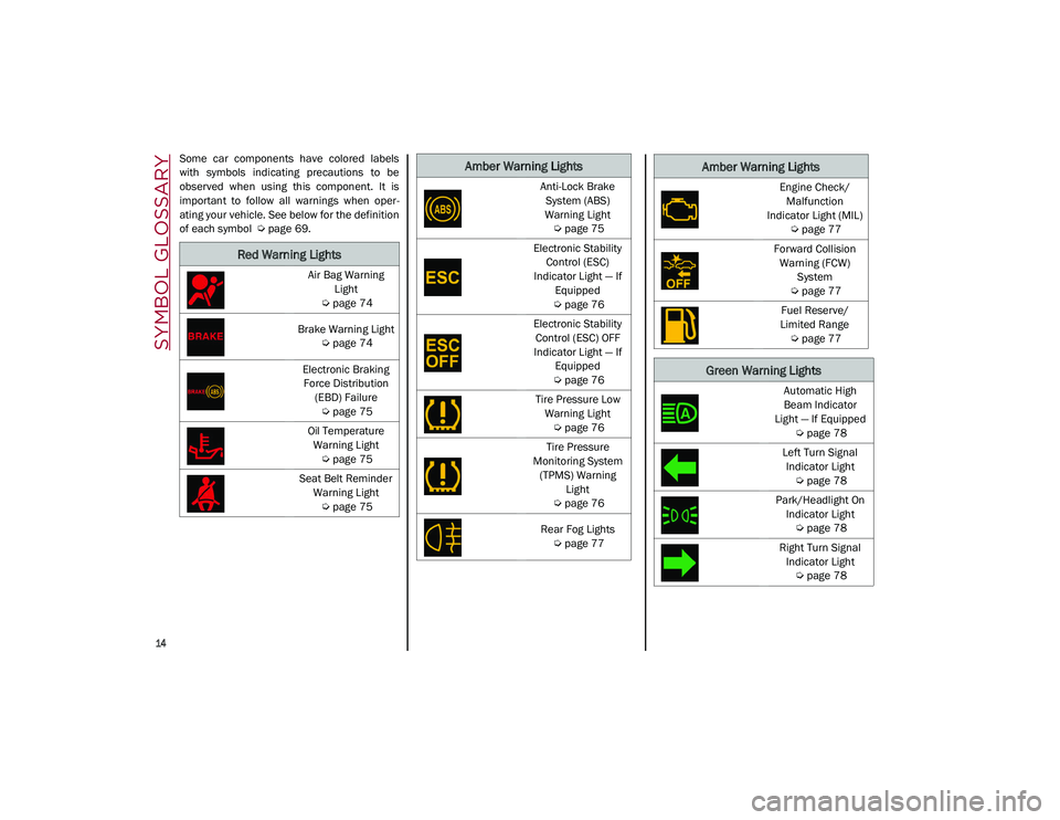
Some car components have colored labels
with symbols indicating precautions to be
observed when using this component. It is
important to follow all warnings when oper-
ating your vehicle. See below for the definition
of each symbol
Ú
page 69.
Red Warning Lights
Air Bag Warning
Light
Ú
page 74
Brake Warning Light
Ú
page 74
Electronic Braking Force Distribution (EBD) Failure
Ú
page 75
Oil Temperature Warning Light
Ú
page 75
Seat Belt Reminder Warning Light
Ú
page 75
Amber Warning Lights
Anti-Lock Brake
System (ABS)
Warning Light
Ú
page 75
Electronic Stability Control (ESC)
Indicator Light — If Equipped
Ú
page 76
Electronic Stability Control (ESC) OFF
Indicator Light — If Equipped
Ú
page 76
Tire Pressure Low Warning Light
Ú
page 76
Tire Pressure
Monitoring System (TPMS) Warning Light
Ú
page 76
Rear Fog Lights
Ú
page 77Engine Check/
Malfunction
Indicator Light (MIL)
Ú
page 77
Forward Collision Warning (FCW) System
Ú
page 77
Fuel Reserve/
Limited Range
Ú
page 77
Green Warning Lights
Automatic High
Beam Indicator
Light — If Equipped
Ú
page 78
Left Turn Signal Indicator Light
Ú
page 78
Park/Headlight On Indicator Light
Ú
page 78
Right Turn Signal Indicator Light
Ú
page 78
Amber Warning Lights
21_GU_OM_EN_USC_t.book Page 14
Page 78 of 280

GETTING TO KNOW YOUR INSTRUMENT PANEL
76
required. However, the conventional brake
system will continue to operate normally if the
brake indicator light is not on.
If the ABS light is on, the brake system should
be serviced as soon as possible to restore the
benefits of Anti-Lock Brakes. If the ABS light
does not turn on when the ignition is placed in
the ON/RUN position, have the light inspected
by an authorized dealer.
Electronic Stability Control (ESC) Indicator
Light — If Equipped
When the ignition is cycled to ON, the
indicator light illuminates, but
should turn off as soon as the engine
is started.
ESC System Intervention : Intervention by the
system is indicated by the flashing of the indi -
cator light: it indicates that the vehicle is in crit -
ical stability and grip conditions.
ESC System Failure : If the indicator light does
not turn off, or if it stays on with the engine
running, a failure was found in the ESC
system.
Hill Start Assist System Failure : The illumina-
tion of the indicator light indicates a Hill Start
Assist system failure.
In these cases, contact an authorized dealer
as soon as possible.
Electronic Stability Control (ESC) OFF
Indicator Light — If Equipped
When the ignition is cycled to ON, the
indicator light illuminates, but
should turn off as soon as the engine
is started.
The indicator light illuminates to indicate that
some active safety systems have been
partially or totally deactivated
Ú
page 145.
When the active safety systems are reacti -
vated, the indicator light turns off.
Tire Pressure Low Warning Light
The indicator light will illuminate to
indicate that the tire pressure is
lower than the recommended value
and/or that slow pressure loss is
occurring. In these cases, optimal tire duration
and fuel consumption may not be guaranteed.
In any situation in which the message on the
display is “See Manual”
Ú
page 161.
Tire Pressure Monitoring System (TPMS)
Warning Light
The warning light switches on and a
message is displayed to indicate
that the tire pressure is lower than
the recommended value and/or that
slow pressure loss is occurring. In these cases,
optimal tire duration and fuel consumption
may not be guaranteed. Should one or more tires be in the condition
mentioned above, the display will show the
indications corresponding to each tire.
Each tire, including the spare (if provided),
should be checked monthly when cold and
inflated to the inflation pressure recom
-
mended by the vehicle manufacturer on the
vehicle placard or tire inflation pressure label.
If your vehicle has tires of a different size than
the size indicated on the vehicle placard or tire
inflation pressure label, you should determine
the proper tire inflation pressure for those
tires.
As an added safety feature, your vehicle has
been equipped with a TPMS that illuminates a
low tire pressure telltale when one or more of
your tires is significantly underinflated. Accord -
ingly, when the low tire pressure telltale illumi -
nates, you should stop and check your tires as
soon as possible, and inflate them to the
proper pressure. Driving on a significantly
underinflated tire causes the tire to overheat
and can lead to tire failure. Under inflation
CAUTION!
Do not continue driving with one or more
flat tires as handling may be compromised.
Stop the vehicle, avoiding sharp braking
and steering. If a tire puncture occurs,
repair immediately using the dedicated tire
repair kit and contact an authorized dealer
as soon as possible.
21_GU_OM_EN_USC_t.book Page 76
Page 79 of 280
77
also reduces fuel efficiency and tire tread life,
and may affect the vehicle’s handling and
stopping ability.
Please note that the TPMS is not a substitute
for proper tire maintenance, and it is the
driver’s responsibility to maintain correct tire
pressure, even if under inflation has not
reached the level to trigger illumination of the
TPMS low tire pressure telltale.
Your vehicle has also been equipped with a
TPMS malfunction indicator to indicate when
the system is not operating properly. The
TPMS malfunction indicator is combined with
the low tire pressure telltale. When the system
detects a malfunction, the telltale will flash for
approximately one minute and then remain
continuously illuminated. This sequence will
continue upon subsequent vehicle start-ups
as long as the malfunction exists. When the
malfunction indicator is illuminated, the
system may not be able to detect or signal low
tire pressure as intended. TPMS malfunctions
may occur for a variety of reasons, including
the installation of replacement or alternate
tires or wheels on the vehicle that prevent the
TPMS from functioning properly. Always check
the TPMS malfunction telltale after replacing
one or more tires or wheels on your vehicle to
ensure that the replacement or alternate tires
and wheels allow the TPMS to continue to
function properly.
Rear Fog Lights
The indicator illuminates when the
rear fog light is activated.
Engine Check/Malfunction Indicator Light
(MIL)
In normal conditions, when the igni-
tion is cycled to ON, the indicator
light illuminates, but it should turn
off as soon as the engine is started.
The operation of the indicator light may be
checked by the traffic police using specific
devices. Comply with the laws and regulations
of the country where you are driving. Under these conditions, the vehicle can
continue traveling at moderate speed but
without demanding excessive effort from the
engine or high speed. Prolonged use of the
vehicle with the indicator light on constantly
may cause damage. Contact an authorized
dealer as soon as possible.
Forward Collision Warning (FCW) System
This indicator light informs the driver
that the frontal collision alarm func
-
tion is not enabled.
Drive carefully and contact an authorized
dealer as soon as possible.
Fuel Reserve/Limited Range
The indicator light (or the symbol in
the display) illuminates when about
2.4 gallons (9 liters) of fuel is left in
the tank.
WARNING!
The TPMS has been optimized for the
original equipment tires and wheels. TPMS
pressures and warning have been
established for the tire size equipped on
your vehicle. Undesirable system operation
or sensor damage may result when using
replacement equipment that is not of the
same size, type, and/or style. Aftermarket
wheels can cause sensor damage. Using
aftermarket tire sealants may cause the
Tire Pressure Monitoring System (TPMS)
sensor to become inoperable. After using
an aftermarket tire sealant it is
recommended that you take your vehicle to
an authorized dealership to have your
sensor function checked.
CAUTION!
If, turning the ignition device to ON, the
warning light does not turn on or if it
turns on steadily or flashing when traveling
(on some versions together with the
message on the display), contact an
authorized dealer as soon as possible.
21_GU_OM_EN_USC_t.book Page 77
Page 138 of 280
STARTING AND OPERATING
136
Gross Vehicle Weight Rating (GVWR)
The GVWR is the total permissible weight of
your vehicle including driver, passengers,
vehicle, options and cargo. The label also
specifies maximum capacities of front and
rear axle systems (GAWR). Total load must be
limited so GVWR and front and rear GAWR are
not exceeded.
Payload
The payload of a vehicle is defined as the
allowable load weight a truck can carry,
including the weight of the driver, all passen-
gers, options and cargo.
Gross Axle Weight Rating (GAWR)
The GAWR is the maximum permissible load
on the front and rear axles. The load must be
distributed in the cargo area so that the GAWR
of each axle is not exceeded.
Each axle GAWR is determined by the compo -
nents in the system with the lowest load
carrying capacity (axle, springs, tires or
wheels). Heavier axles or suspension compo -
nents sometimes specified by purchasers for
increased durability do not necessarily
increase the vehicle's GVWR.
Tire Size
The tire size on the Vehicle Certification Label
represents the actual tire size on your vehicle.
Replacement tires must be equal to the load
capacity of this tire size.
Rim Size
This is the rim size that is appropriate for the
tire size listed.
Inflation Pressure
This is the cold tire inflation pressure for your
vehicle for all loading conditions up to full
GAWR.
Curb Weight
The curb weight of a vehicle is defined as the
total weight of the vehicle with all fluids,
including vehicle fuel, at full capacity condi -
tions, and with no occupants or cargo loaded
into the vehicle. The front and rear curb weight
values are determined by weighing your
vehicle on a commercial scale before any
occupants or cargo are added.
Loading
The actual total weight and the weight of the
front and rear of your vehicle at the ground can
best be determined by weighing it when it is
loaded and ready for operation.
The entire vehicle should first be weighed on a
commercial scale to ensure that the GVWR
has not been exceeded. The weight on the
front and rear of the vehicle should then be
determined separately to be sure that the load
is properly distributed over the front and rear
axle. Weighing the vehicle may show that the
GAWR of either the front or rear axles has
been exceeded but the total load is within the specified GVWR. If so, weight must be shifted
from front to rear or rear to front as appro
-
priate until the specified weight limitations are
met. Store the heavier items down low and be
sure that the weight is distributed equally.
Stow all loose items securely before driving.
Improper weight distributions can have an
adverse effect on the way your vehicle steers
and handles and the way the brakes operate.
TRAILER TOWING
In this section you will find safety tips and
information on limits to the type of towing you
can reasonably do with your vehicle. Before
towing a trailer, carefully review this informa -
tion to tow your load as efficiently and safely
as possible.
To maintain the New Vehicle Limited Warranty
coverage, follow the requirements and recom -
mendations in this manual concerning vehi -
cles used for trailer towing.
CAUTION!
Do not load your vehicle any heavier than
the GVWR or the maximum front and rear
GAWR. If you do, parts on your vehicle can
break, or it can change the way your vehicle
handles. This could cause you to lose
control. Also overloading can shorten the
life of your vehicle.
21_GU_OM_EN_USC_t.book Page 136
Page 141 of 280
139
(Continued)
Consider the following items when computing
the weight on the rear axle of the vehicle:
The tongue weight of the trailer.
The weight of any other type of cargo or
equipment put in or on your vehicle.
The weight of the driver and all passengers.
NOTE:
Remember that everything put into or on the
trailer adds to the load on your vehicle. Also,
additional factory-installed options or
dealer-installed options must be considered
as part of the total load on your vehicle. Refer
to the “Tire And Loading Information” placard
for the maximum combined weight of occu -
pants and cargo for your vehicle.
Towing Requirements
To promote proper break-in of your new
vehicle drivetrain components, the following
guidelines are recommended:
Towing Requirements — Tires
Do not attempt to tow a trailer while using a
compact spare tire.
Do not drive more than 50 mph (80 km/h)
when towing while using a full size spare
tire.
Proper tire inflation pressures are essential
to the safe and satisfactory operation of
your vehicle.
Check the trailer tires for proper tire infla -
tion pressures before trailer usage.
Check for signs of tire wear or visible tire
damage before towing a trailer.
Replacing tires with a higher load carrying
capacity will not increase the vehicle's
GVWR and GAWR limits.
For proper tire inflation procedures
Ú
page 233.
WARNING!
Improper towing can lead to a collision.
Follow these guidelines to make your trailer
towing as safe as possible:
Make certain that the load is secured in
the trailer and that it will not shift during
travel. When trailering cargo that is not
fully secured, dynamic load shifts can
occur that may be difficult for the driver to
control. You could lose control of your
vehicle and have a collision.
When hauling cargo, or towing a trailer, do
not overload your vehicle or trailer. Over -
loading can cause a loss of control, poor
performance, or damage to brakes, axle,
engine, transmission, steering, suspen -
sion, chassis structure, or tires.
Safety chains must always be used
between your vehicle and trailer. Always
connect the chains to the frame or hook
retainers of the vehicle hitch. Cross the
chains under the trailer tongue and allow
enough slack for turning corners.
Vehicles with trailers should not be parked
on a grade. When parking, apply the
parking brake on the tow vehicle. Put the
tow vehicle transmission in PARK. Always
block or "chock" the trailer wheels.
GCWR must not be exceeded.
Total weight must be distributed between
the tow vehicle and the trailer such that
the following four ratings are not
exceeded:
• GVWR
• GTW
• GAWR
• Tongue weight rating for the trailer
hitch utilized.
WARNING! (Continued) CAUTION!
Do not tow a trailer at all during the first
500 miles (805 km) the new vehicle is
driven. The engine, axle or other parts
could be damaged.
Then, during the first 500 miles (805 km)
that a trailer is towed, do not drive over
50 mph (80 km/h) and do not make
starts at full throttle. This helps the engine
and other parts of the vehicle wear in at
the heavier loads.
21_GU_OM_EN_USC_t.book Page 139
Page 144 of 280
STARTING AND OPERATING
142
Removing The Receiver
When the receiver is no longer needed, discon-
nect the electrical connections and remove it
from its position using the directions below:
1. Remove the safety split ring from the locking pin.
2. Pull the locking pin out of the trailer hitch.
3. Remove the receiver from the trailer hitch.
SUGGESTIONS FOR DRIVING
Saving Fuel
Below are some suggestions which may help
you save fuel and lower the amount of harmful
emissions released into the atmosphere.
Vehicle Maintenance
Checks and operations should be carried out
in accordance with the Maintenance Plan
Ú
page 208.
Tires
Check the tire pressures at least once every
four weeks: if the pressure is too low,
consumption levels increase as resistance to
rolling is higher.
NOTE:
Tire pressure that is too high can cause
premature tire wear, reduced control, etc. Unnecessary Loads
Do not travel with an overloaded liftgate. The
weight of the vehicle and its arrangement
greatly affect fuel consumption and stability.
Electric Devices
Use electrical systems only for the amount of
time needed. The rear window defroster, addi
-
tional headlights, windshield wipers and
heater blower fan require a considerable
amount of energy; increasing the current
uptake increases fuel consumption (by up to
+25% when city driving).
Climate Control System
Using the climate control system will increase
consumption: use standard ventilation when
the temperature outside permits.
Devices For Aerodynamic Control
The use of non-certified devices for aerody -
namic control may adversely affect air drag
and consumption levels.
Driving Style
Starting
Do not warm up the engine at low or high revs
when the vehicle is stationary; this causes the
engine to warm up more slowly, thereby
increasing fuel consumption and emissions. It
is therefore advisable to drive off immediately,
slowly, avoiding high speeds: by doing this the
engine will warm up more quickly. Unnecessary Actions
Avoid revving up when starting at traffic lights
or before stopping the engine. This action is
unnecessary and causes increased fuel
consumption and pollution.
Gear Selection
Use a high gear when traffic and road condi
-
tions allow it. Using a low gear for faster accel -
eration will increase fuel consumption.
Improper use of a high gear increases
consumption, emissions and engine wear.
Max. Speed
Fuel consumption considerably increases as
speed increases. Maintain a constant speed,
avoiding unnecessary braking and accelera -
tion, which cost in terms of both fuel consump -
tion and emissions.
Acceleration
Accelerating violently severely affects
consumption and emissions: acceleration
should be gradual and should not exceed the
maximum torque.Conditions Of Use
Cold Starting
Short trips and frequent cold starts will not
allow the engine to reach optimum operating
temperature. This results in a significant
increase in consumption levels (from +15 to
+30% in city driving) and emissions.
21_GU_OM_EN_USC_t.book Page 142
Page 151 of 280
149
Panic Brake Assist (PBA) System
The PBA system is designed to improve the
vehicle’s braking capacity during emergency
braking.
The system detects emergency braking by
monitoring the speed and force with which the
brake pedal is pressed, and consequently
applies the optimal brake pressure. This can
reduce the braking distance: the PBA system
therefore complements the ABS.
Maximum assistance from the PBA system is
obtained by pressing the brake pedal very
quickly. In addition, the brake pedal should be
pressed continuously during braking, avoiding
intermittent presses, to get the most out of thesystem. Do not reduce pressure on the brake
pedal until braking is no longer necessary.
The PBA system is deactivated when the brake
pedal is released.Traction Control System (TCS)
The TCS automatically operates in the event of
slipping, loss of grip on wet roads (hydro
-
planing), and acceleration on one or both drive
wheels on roads that are slippery, snowy, icy,
etc. Depending on the slipping conditions, two
different control systems are activated:
If the slipping involves both drive wheels,
the system intervenes, reducing the power
transmitted by the engine.
If the slipping only involves one of the drive
wheels, the Brake Limited Differential (BLD)
function is activated, automatically braking the wheel which is slipping (the behavior of
a self-locking differential is simulated). This
will increase the engine torque transferred
to the wheel which isn't slipping.
System Intervention
The intervention of the system is indicated by
the flashing of the ESC warning light on the
instrument panel, to inform the driver that the
vehicle stability and grip are critical.
AUXILIARY DRIVING SYSTEMS
The following auxiliary driving systems are
available in this vehicle:
Blind Spot Monitoring (BSM) — if equipped
Active Blind Spot Assist (ABSA) — if
equipped
Forward Collision Warning Plus (FCW+)
Tire Pressure Monitoring System (TPMS)
The vehicle may also be fitted with the
following driving assistance systems:
Driver Attention Assist (DAA)
Lane Departure Warning (LDW)
Lane Keeping Assist (LKA)
Highway Assist System (HAS)
Traffic Jam Assist (TJA)
Adaptive Cruise Control (ACC)
Intelligent Speed Control (ISC)
Traffic Sign Recognition (TSR)
WARNING!
There may be situations where the Hill Start
Assist (HSA) will not activate and slight
rolling may occur, such as on minor hills or
with a loaded vehicle, or while pulling a
trailer. HSA is not a substitute for active
driving involvement. It is always the driver’s
responsibility to be attentive to distance to
other vehicles, people, and objects, and
most importantly brake operation to ensure
safe operation of the vehicle under all road
conditions. Your complete attention is
always required while driving to maintain
safe control of your vehicle. Failure to follow
these warnings can result in a collision or
serious personal injury.
WARNING!
The Panic Brake Assist (PBA) cannot
prevent the natural laws of physics from
acting on the vehicle, nor can it increase
the traction afforded by prevailing road
conditions. PBA cannot prevent collisions,
including those resulting from excessive
speed in turns, driving on very slippery
surfaces, or hydroplaning. The capabilities
of a PBA-equipped vehicle must never be
exploited in a reckless or dangerous
manner, which could jeopardize the user's
safety or the safety of others.
21_GU_OM_EN_USC_t.book Page 149
Page 163 of 280
161
Tire Pressure Monitoring System (TPMS)
The vehicle is equipped with a Tire Pressure
Monitoring System (TPMS) that sends the
inflation pressure information of each tire to
the control unit, and will signal the driver in the
event of insufficient tire pressure.
The TPMS uses wireless technology with wheel
rim mounted electronic sensors to monitor tire
pressure levels. Sensors, mounted to each
wheel as part of the valve stem, transmit tire
pressure readings to the receiver module.
Tire pressure will vary with temperature by
approximately 1 psi (7 kPa) for every 12°F
(6.5°C). This means that when the outside
temperature decreases, the tire pressure will
also decrease. Tire pressure should always be
set based on cold inflation tire pressure. This
is defined as the tire pressure after the vehicle
has not been driven for at least three hours, or
driven less than 1 mile (1.6 km) after a three
hour period. The cold tire inflation pressure
must not exceed the maximum inflation pres-
sure molded into the tire sidewall. The tire
pressure will also increase as the vehicle is
driven. This is normal, and there should be no
adjustment for this increased pressure.
See
Ú
page 233 for information on how to
properly inflate the vehicle’s tires.
The TPMS will signal the driver if pressure falls
below the warning limit for any reason,
including the effects of low temperature and
normal loss of pressure from the tire. The TPMS will stop indicating insufficient tire
pressure when pressure is equal to or greater
than the prescribed cold inflation level. There
-
fore, if insufficient tire pressure is indicated by
the ( ) warning light displaying in the instru -
ment cluster, increase the inflation pressure
up to the prescribed cold inflation value.
The system will automatically update, and the
TPMS Warning Light will turn off once the
system receives the updated tire pressures.
The vehicle may need to be driven for up to
20 minutes above 15 mph (24 km/h) in order
for the TPMS to receive this information.
NOTE:
The TPMS cannot indicate sudden tire pres -
sure drops (e.g. if a tire bursts). In this case,
proceed with caution and avoid abrupt
steering.
Operating Example
For example, your vehicle may have a recom -
mended cold (parked for more than three
hours) placard pressure of 33 psi (227 kPa). If
the ambient temperature is 68°F (20°C), and
the measured tire pressure is 28 psi (193 kPa),
a temperature drop to 20°F (-7°C) will
decrease the tire pressure to approximately
24 psi (165 kPa). This tire pressure is low
enough to turn on the “Tire Pressure Monitoring
Warning Light.” Driving the vehicle may cause
the tire pressure to rise to approximately 28 psi
(193 kPa), but the TPMS Warning Light will still
be on. In this situation, the TPMS Warning Light
WARNING!
The system has not been designed to
prevent impacts and cannot detect
possible conditions leading to an accident
in advance. Failure to take into account
this warning may lead to serious or fatal
injuries.
The system may activate, assessing the
trajectory of the vehicle, for the presence
of reflecting metal objects different from
other vehicles, such as safety barriers,
road signs, barriers before parking lots,
tollgates, level crossings, gates, railways,
objects near road constructions sites or
higher than the vehicle (e.g. a fly-over). In
the same way, the system may intervene
inside multi-story parking lots or tunnels,
or due to a glare on the road surface.
These possible activations are a conse -
quence of the real driving scenario
coverage by the system and must not be
regarded as faults.
The system has been designed for road
use only. If the vehicle is driven on a track,
the system must be deactivated to avoid
unnecessary warnings. Automatic deacti -
vation is signaled by the dedicated
warning light/symbol switching on in the
instrument panel
Ú
page 74.
21_GU_OM_EN_USC_t.book Page 161