inflation pressure ALFA ROMEO STELVIO 2023 Owners Manual
[x] Cancel search | Manufacturer: ALFA ROMEO, Model Year: 2023, Model line: STELVIO, Model: ALFA ROMEO STELVIO 2023Pages: 268, PDF Size: 10.36 MB
Page 14 of 268
12
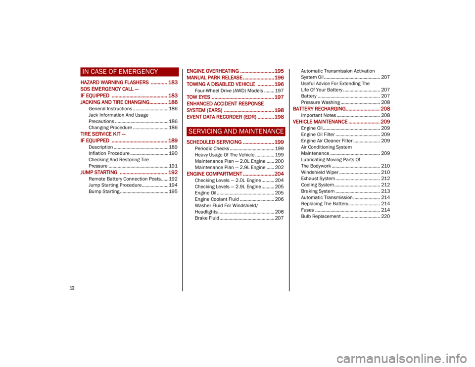
IN CASE OF EMERGENCY
HAZARD WARNING FLASHERS ............ 183
SOS EMERGENCY CALL —
IF EQUIPPED ......................................... 183
JACKING AND TIRE CHANGING............. 186
General Instructions ............................186
Jack Information And Usage
Precautions ..........................................186 Changing Procedure ............................186
TIRE SERVICE KIT —
IF EQUIPPED ......................................... 189
Description ...........................................189
Inflation Procedure .............................. 190
Checking And Restoring Tire
Pressure ...............................................191
JUMP STARTING ................................... 192
Remote Battery Connection Posts......192
Jump Starting Procedure.....................194
Bump Starting ...................................... 195
ENGINE OVERHEATING ......................... 195
MANUAL PARK RELEASE ....................... 196
TOWING A DISABLED VEHICLE ............ 196
Four-Wheel Drive (AWD) Models ........ 197
TOW EYES .............................................. 197
ENHANCED ACCIDENT RESPONSE
SYSTEM (EARS) ..................................... 198
EVENT DATA RECORDER (EDR) ............ 198
SERVICING AND MAINTENANCE
SCHEDULED SERVICING ....................... 199
Periodic Checks ................................... 199
Heavy Usage Of The Vehicle ............... 199
Maintenance Plan — 2.0L Engine ...... 200
Maintenance Plan — 2.9L Engine ...... 202
ENGINE COMPARTMENT ....................... 204
Checking Levels — 2.0L Engine .......... 204
Checking Levels — 2.9L Engine .......... 205
Engine Oil ............................................. 205
Engine Coolant Fluid ........................... 206
Washer Fluid For Windshield/
Headlights ............................................ 206 Brake Fluid ........................................... 207 Automatic Transmission Activation
System Oil ............................................ 207 Useful Advice For Extending The
Life Of Your Battery ............................. 207 Battery ................................................. 207
Pressure Washing ............................... 208
BATTERY RECHARGING......................... 208
Important Notes .................................. 208
VEHICLE MAINTENANCE ....................... 209
Engine Oil............................................. 209
Engine Oil Filter ................................... 209
Engine Air Cleaner Filter ..................... 209
Air Conditioning System
Maintenance ....................................... 209 Lubricating Moving Parts Of
The Bodywork ...................................... 210 Windshield Wiper ................................ 210
Exhaust System ................................... 212
Cooling System.................................... 212
Braking System ................................... 213
Automatic Transmission ..................... 214
Replacing The Battery......................... 214
Fuses ................................................... 214
Bulb Replacement .............................. 220
23_GU_OM_EN_USC_t.book Page 12
Page 79 of 268
77
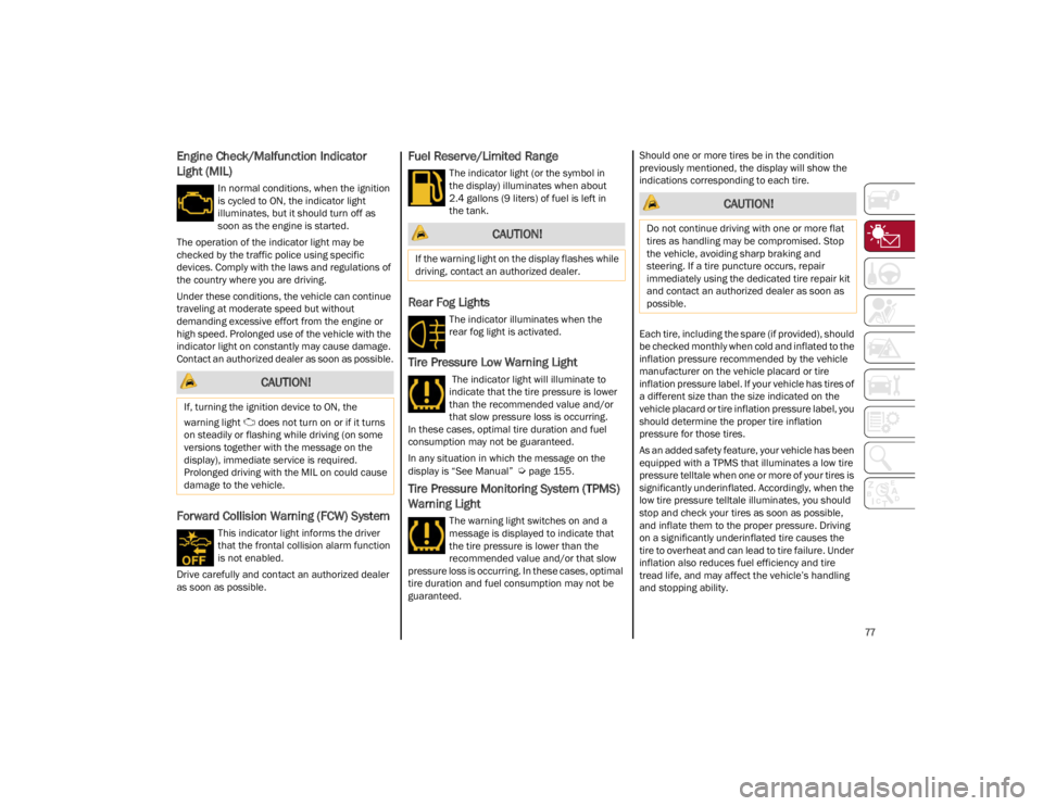
Engine Check/Malfunction Indicator
Light (MIL)
In normal conditions, when the ignition
is cycled to ON, the indicator light
illuminates, but it should turn off as
soon as the engine is started.
The operation of the indicator light may be
checked by the traffic police using specific
devices. Comply with the laws and regulations of
the country where you are driving.
Under these conditions, the vehicle can continue
traveling at moderate speed but without
demanding excessive effort from the engine or
high speed. Prolonged use of the vehicle with the
indicator light on constantly may cause damage.
Contact an authorized dealer as soon as possible.
Forward Collision Warning (FCW) System
This indicator light informs the driver
that the frontal collision alarm function
is not enabled.
Drive carefully and contact an authorized dealer
as soon as possible.
Fuel Reserve/Limited Range
The indicator light (or the symbol in
the display) illuminates when about
2.4 gallons (9 liters) of fuel is left in
the tank.
Rear Fog Lights
The indicator illuminates when the
rear fog light is activated.
Tire Pressure Low Warning Light
The indicator light will illuminate to
indicate that the tire pressure is lower
than the recommended value and/or
that slow pressure loss is occurring.
In these cases, optimal tire duration and fuel
consumption may not be guaranteed.
In any situation in which the message on the
display is “See Manual”
Ú
page 155.
Tire Pressure Monitoring System (TPMS)
Warning Light
The warning light switches on and a
message is displayed to indicate that
the tire pressure is lower than the
recommended value and/or that slow
pressure loss is occurring. In these cases, optimal
tire duration and fuel consumption may not be
guaranteed. Should one or more tires be in the condition
previously mentioned, the display will show the
indications corresponding to each tire.
Each tire, including the spare (if provided), should
be checked monthly when cold and inflated to the
inflation pressure recommended by the vehicle
manufacturer on the vehicle placard or tire
inflation pressure label. If your vehicle has tires of
a different size than the size indicated on the
vehicle placard or tire inflation pressure label, you
should determine the proper tire inflation
pressure for those tires.
As an added safety feature, your vehicle has been
equipped with a TPMS that illuminates a low tire
pressure telltale when one or more of your tires is
significantly underinflated. Accordingly, when the
low tire pressure telltale illuminates, you should
stop and check your tires as soon as possible,
and inflate them to the proper pressure. Driving
on a significantly underinflated tire causes the
tire to overheat and can lead to tire failure. Under
inflation also reduces fuel efficiency and tire
tread life, and may affect the vehicle’s handling
and stopping ability.
CAUTION!
If, turning the ignition device to ON, the
warning light does not turn on or if it turns
on steadily or flashing while driving (on some
versions together with the message on the
display), immediate service is required.
Prolonged driving with the MIL on could cause
damage to the vehicle.
CAUTION!
If the warning light on the display flashes while
driving, contact an authorized dealer.
CAUTION!
Do not continue driving with one or more flat
tires as handling may be compromised. Stop
the vehicle, avoiding sharp braking and
steering. If a tire puncture occurs, repair
immediately using the dedicated tire repair kit
and contact an authorized dealer as soon as
possible.
23_GU_OM_EN_USC_t.book Page 77
Page 80 of 268
GETTING TO KNOW YOUR INSTRUMENT PANEL
78
Please note that the TPMS is not a substitute for
proper tire maintenance, and it is the driver’s
responsibility to maintain correct tire pressure,
even if under inflation has not reached the level
to trigger illumination of the TPMS low tire
pressure telltale.
Your vehicle has also been equipped with a
TPMS malfunction indicator to indicate when the
system is not operating properly. The TPMS
malfunction indicator is combined with the low
tire pressure telltale. When the system detects a
malfunction, the telltale will flash for approxi-
mately one minute and then remain continuously
illuminated. This sequence will continue upon
subsequent vehicle start-ups as long as the
malfunction exists. When the malfunction
indicator is illuminated, the system may not be
able to detect or signal low tire pressure as
intended. TPMS malfunctions may occur for a
variety of reasons, including the installation of
replacement or alternate tires or wheels on the
vehicle that prevent the TPMS from functioning
properly. Always check the TPMS malfunction
telltale after replacing one or more tires or wheels
on your vehicle to ensure that the replacement or
alternate tires and wheels allow the TPMS to
continue to function properly.
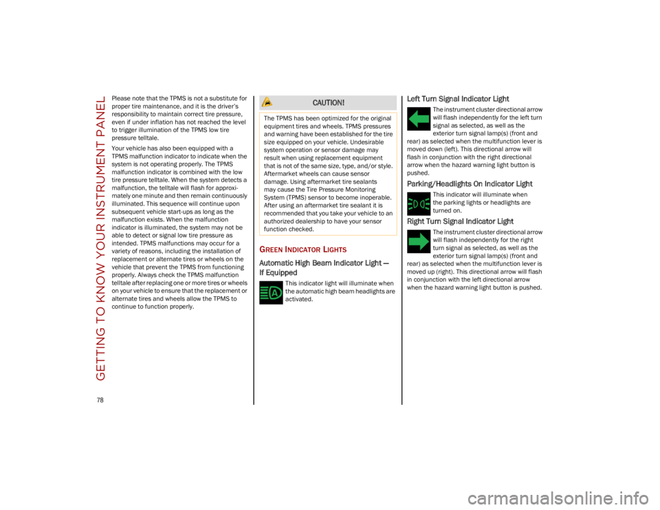
GREEN INDICATOR LIGHTS
Automatic High Beam Indicator Light —
If Equipped
This indicator light will illuminate when
the automatic high beam headlights are
activated.
Left Turn Signal Indicator Light
The instrument cluster directional arrow
will flash independently for the left turn
signal as selected, as well as the
exterior turn signal lamp(s) (front and
rear) as selected when the multifunction lever is
moved down (left). This directional arrow will
flash in conjunction with the right directional
arrow when the hazard warning light button is
pushed.
Parking/Headlights On Indicator Light
This indicator will illuminate when
the parking lights or headlights are
turned on.
Right Turn Signal Indicator Light
The instrument cluster directional arrow
will flash independently for the right
turn signal as selected, as well as the
exterior turn signal lamp(s) (front and
rear) as selected when the multifunction lever is
moved up (right). This directional arrow will flash
in conjunction with the left directional arrow
when the hazard warning light button is pushed.
CAUTION!
The TPMS has been optimized for the original
equipment tires and wheels. TPMS pressures
and warning have been established for the tire
size equipped on your vehicle. Undesirable
system operation or sensor damage may
result when using replacement equipment
that is not of the same size, type, and/or style.
Aftermarket wheels can cause sensor
damage. Using aftermarket tire sealants
may cause the Tire Pressure Monitoring
System (TPMS) sensor to become inoperable.
After using an aftermarket tire sealant it is
recommended that you take your vehicle to an
authorized dealership to have your sensor
function checked.
23_GU_OM_EN_USC_t.book Page 78
Page 134 of 268
STARTING AND OPERATING
132
VEHICLE LOADING
CERTIFICATION LABEL
As required by National Highway Traffic Safety
Administration regulations, your vehicle has a
certification label affixed to the driver's side door
or pillar.
This label contains the month and year of
manufacture, Gross Vehicle Weight Rating
(GVWR), Gross Axle Weight Rating (GAWR) front
and rear, and Vehicle Identification Number
(VIN). A Month-Day-Hour (MDH) number is
included on this label and indicates the Month,
Day and Hour of manufacture. The bar code that
appears on the bottom of the label is your VIN.
Gross Vehicle Weight Rating (GVWR)
The GVWR is the total permissible weight of your
vehicle including driver, passengers, vehicle,
options and cargo. The label also specifies
maximum capacities of front and rear axle
systems (GAWR). Total load must be limited so
GVWR and front and rear GAWR are not
exceeded.
Payload
The payload of a vehicle is defined as the
allowable load weight a truck can carry, including
the weight of the driver, all passengers, options
and cargo.
Gross Axle Weight Rating (GAWR)
The GAWR is the maximum permissible load on
the front and rear axles. The load must be
distributed in the cargo area so that the GAWR of
each axle is not exceeded.
Each axle GAWR is determined by the
components in the system with the lowest load
carrying capacity (axle, springs, tires or wheels).
Heavier axles or suspension components
sometimes specified by purchasers for increased
durability do not necessarily increase the
vehicle's GVWR.
Tire Size
The tire size on the Vehicle Certification Label
represents the actual tire size on your vehicle.
Replacement tires must be equal to the load
capacity of this tire size.
Rim Size
This is the rim size that is appropriate for the
tire size listed.
Inflation Pressure
This is the cold tire inflation pressure for your
vehicle for all loading conditions up to full GAWR.
Curb Weight
The curb weight of a vehicle is defined as the total
weight of the vehicle with all fluids, including
vehicle fuel, at full capacity conditions, and with
no occupants or cargo loaded into the vehicle.
The front and rear curb weight values are
determined by weighing your vehicle on a
commercial scale before any occupants or
cargo are added.
Loading
The actual total weight and the weight of the front
and rear of your vehicle at the ground can best be
determined by weighing it when it is loaded and
ready for operation.
The entire vehicle should first be weighed on a
commercial scale to ensure that the GVWR has
not been exceeded. The weight on the front and
rear of the vehicle should then be determined
separately to be sure that the load is properly
distributed over the front and rear axle. Weighing
the vehicle may show that the GAWR of either the
front or rear axles has been exceeded but the
total load is within the specified GVWR. If so,
weight must be shifted from front to rear or rear
to front as appropriate until the specified weight
limitations are met. Store the heavier items down
low and be sure that the weight is distributed
equally. Stow all loose items securely before
driving.
Improper weight distributions can have an
adverse effect on the way your vehicle steers and
handles and the way the brakes operate.
WARNING!
Do not load your vehicle any heavier than the
GVWR or the maximum front and rear GAWR. If
you do, parts on your vehicle can break, or it
can change the way your vehicle handles. This
could cause you to lose control. Overloading
can shorten the life of your vehicle.
23_GU_OM_EN_USC_t.book Page 132
Page 138 of 268
STARTING AND OPERATING
136
Towing Requirements — Tires
Do not attempt to tow a trailer while using a
compact spare tire.
Do not drive more than 50 mph (80 km/h)
when towing while using a full size spare tire.
Proper tire inflation pressures are essential to
the safe and satisfactory operation of your
vehicle.
Check the trailer tires for proper tire inflation
pressures before trailer usage.
Check for signs of tire wear or visible tire
damage before towing a trailer.
Replacing tires with a higher load carrying
capacity will not increase the vehicle's GVWR
and GAWR limits.
For proper tire inflation procedures
Ú
page 224.
Towing Requirements — Trailer Brakes
Do not interconnect the hydraulic brake
system or vacuum system of your vehicle with
that of the trailer. This could cause inadequate
braking and possible personal injury.
An electronically actuated trailer brake
controller is required when towing a trailer with
electronically actuated brakes. When towing a
trailer equipped with a hydraulic surge
actuated brake system, an electronic brake
controller is not required.
Trailer brakes are recommended for trailers
over 1,000 lb (453 kg) and required for trailers
in excess of 2,000 lb (907 kg).
Towing Requirements — Trailer Lights
And Wiring
Whenever you pull a trailer, regardless of the
trailer size, stoplights and turn signals on the
trailer are required for motoring safety.
The Trailer Tow Package may include a four- and
seven-pin wiring harness. Use a factory approved
trailer harness and connector.
NOTE:
Do not cut or splice wiring into the vehicle’s wiring
harness.
The electrical connections are all complete to the
vehicle but you must mate the harness to a trailer
connector. Refer to the following illustrations.
NOTE:
Disconnect trailer wiring connector from the
vehicle before launching a boat (or any other
device plugged into vehicle’s electrical
connect) into water.
Be sure to reconnect once clear from
water area.
Then, during the first 500 miles (805 km)
that a trailer is towed, do not drive over
50 mph (80 km/h) and do not make starts
at full throttle. This helps the engine and
other parts of the vehicle wear in at the
heavier loads.
CAUTION!
WARNING!
Do not connect trailer brakes to your
vehicle's hydraulic brake lines. It can
overload your brake system and cause it to
fail. You might not have brakes when you
need them and could have an accident.
Towing any trailer will increase your stopping
distance. When towing, you should allow for
additional space between your vehicle and
the vehicle in front of you. Failure to do so
could result in an accident.
CAUTION!
If the trailer weighs more than 1,000 lb
(453 kg) loaded, it should have its own brakes
and they should be of adequate capacity.
Failure to do this could lead to accelerated
brake lining wear, higher brake pedal effort,
and longer stopping distances.
23_GU_OM_EN_USC_t.book Page 136
Page 157 of 268
155
TIRE PRESSURE MONITORING SYSTEM
(TPMS)
The vehicle is equipped with a Tire Pressure
Monitoring System (TPMS) that sends the
inflation pressure information of each tire to the
control unit, and will signal the driver in the event
of insufficient tire pressure.
The TPMS uses wireless technology with wheel
rim mounted electronic sensors to monitor tire
pressure levels. Sensors, mounted to each wheel
as part of the valve stem, transmit tire pressure
readings to the receiver module.
Tire pressure will vary with temperature by
approximately 1 psi (7 kPa) for every 12°F
(6.5°C). This means that when the outside
temperature decreases, the tire pressure will also
decrease. Tire pressure should always be set
based on cold inflation tire pressure. This is
defined as the tire pressure after the vehicle has
not been driven for at least three hours, or driven
less than 1 mile (1.6 km) after a three hour
period. The cold tire inflation pressure must not
exceed the maximum inflation pressure molded
into the tire sidewall. The tire pressure will also
increase as the vehicle is driven. This is normal,
and there should be no adjustment for this
increased pressure.
See
Ú
page 224 for information on how to
properly inflate the vehicle’s tires.
The TPMS will signal the driver if pressure falls
below the warning limit for any reason, including
the effects of low temperature and normal loss of
pressure from the tire.
The TPMS will stop indicating insufficient tire
pressure when pressure is equal to or greater than
the prescribed cold inflation level. Therefore, if
insufficient tire pressure is indicated by the ( )
warning light displaying in the instrument cluster,
increase the inflation pressure up to the
prescribed cold inflation value.
The system will automatically update, and the
TPMS Warning Light will turn off once the system
receives the updated tire pressures. The vehicle
may need to be driven for up to 20 minutes above
15 mph (24 km/h) in order for the TPMS to
receive this information.
NOTE:
The TPMS cannot indicate sudden tire pressure
drops (e.g. if a tire bursts). In this case, proceed
with caution and avoid abrupt steering.
Operating Example
For example, your vehicle may have a
recommended cold (parked for more than three
hours) placard pressure of 33 psi (227 kPa). If the
ambient temperature is 68°F (20°C), and the
measured tire pressure is 28 psi (193 kPa), a
temperature drop to 20°F (-7°C) will decrease
the tire pressure to approximately 24 psi
(165 kPa). This tire pressure is low enough to turn
on the Tire Pressure Monitoring Warning Light.
Driving the vehicle may cause the tire pressure to
rise to approximately 28 psi (193 kPa), but the
TPMS Warning Light will still be on. In this
situation, the TPMS Warning Light will turn off
only after the tires are inflated to the vehicle’s
recommended cold placard pressure value.
WARNING!
The system has not been designed to
prevent impacts and cannot detect possible
conditions leading to an accident in
advance. Failure to take into account this
warning may lead to serious or fatal injuries.
The system may activate, assessing the
trajectory of the vehicle, for the presence of
reflecting metal objects different from other
vehicles, such as safety barriers, road signs,
barriers before parking lots, tollgates, level
crossings, gates, railways, objects near road
constructions sites or higher than the vehicle
(e.g. a fly-over). In the same way, the system
may intervene inside multi-story parking lots
or tunnels, or due to a glare on the road
surface. These possible activations are a
consequence of the real driving scenario
coverage by the system and must not be
regarded as faults.
The system has been designed for road use
only. If the vehicle is driven on a track, the
system must be deactivated to avoid
unnecessary warnings. Automatic deacti
-
vation is signaled by the dedicated warning
light/symbol switching on in the instrument
panel
Ú
page 74.
23_GU_OM_EN_USC_t.book Page 155
Page 158 of 268
SAFETY
156
Insufficient Tire Pressure Indication
If an insufficient pressure value is detected on
one or more tires, the warning light in the
instrument cluster will display alongside the
dedicated messages, the system will highlight the
tire or tires with insufficient pressure graphically,
and an acoustic signal will be emitted.In this case, stop the vehicle, check the inflation
pressure of each tire, and inflate the necessary
tire or tires to the correct cold inflation pressure
value, shown on the display or in the dedicated
TPMS menu.
TPMS Temporarily Disabled:
TPMS Check Message
When a system fault is detected, the TPMS
Warning Light will flash on and off for 75 seconds,
and then remain on solid. The system fault will
also sound a chime. If the ignition is cycled, this
sequence will repeat, provided that the system
fault still exists. The TPMS Warning Light will turn
off when the fault condition no longer exists. A
system fault can occur due to any of the following:
Jamming due to electronic devices or driving
next to facilities emitting the same radio
frequencies as the TPMS sensors.
Installing some form of aftermarket window
tinting that affects radio wave signals.
Packed snow or ice around the wheels or
wheel housings.
Using tire chains on the vehicle.
Using wheels/tires not equipped with
TPMS sensors.
After the punctured tire has been repaired with
the original tire sealant contained in the tire kit,
the previous condition must be restored so that
the warning light is off during normal driving.
TPMS Deactivation
The TPMS can be deactivated by replacing all
four wheel and tire assemblies (road tires) with
wheel and tire assemblies that do not have TPMS
sensors, such as when installing winter wheel
and tire assemblies on your vehicle. To deactivate the TPMS, first replace all four
wheel and tire assemblies (road tires) with tires
not equipped with Tire Pressure Monitoring
System (TPMS) sensors. Then, drive the vehicle
for 20 minutes above 15 mph (24 km/h). The
TPMS will chime, the TPMS Warning Light will
flash on and off for 75 seconds and then remain
on. The instrument cluster will display the
“SERVICE TPM SYSTEM” message and then
display dashes (--) in place of the pressure values.
Beginning with the next ignition switch cycle, the
TPMS will no longer chime or display the
“SERVICE TPM SYSTEM” message in the
instrument cluster. Instead, dashes (--) will
remain in place of the pressure values.
To reactivate the TPMS, replace all four wheel
and tire assemblies (road tires) with tires
equipped with TPMS sensors. Then, drive the
vehicle for up to 20 minutes above 15 mph
(24 km/h). The TPMS will chime, the TPMS
Warning Light will flash on and off for 75 seconds
and then turn off. The instrument cluster will
display the “SERVICE TPM SYSTEM” message
and then display pressure values in place of the
dashes. On the next ignition switch cycle the
“SERVICE TPM SYSTEM” message will no longer
be displayed, as long as no system fault exists.
NOTE:
The TPMS is not intended to replace normal
tire care and maintenance, or to provide
warning of a tire failure or condition.
The TPMS should not be used as a tire
pressure gauge while adjusting your tire
pressure.
CAUTION!
The TPMS has been optimized for the original
equipment tires and wheels. TPMS
pressures and warning have been
established for the tire size equipped on your
vehicle. Undesirable system operation or
sensor damage may result when using
replacement equipment that is not of the
same size, type, and/or style. The TPMS
sensor is not designed for use on
aftermarket wheels and may contribute to a
poor overall system performance or sensor
damage. Customers are encouraged to use
Original Equipment Manufacturer (OEM)
wheels to ensure proper TPMS feature
operation.
Using aftermarket tire sealants may cause
the Tire Pressure Monitoring System (TPMS)
sensor to become inoperable. After using an
aftermarket tire sealant it is recommended
that you take your vehicle to an authorized
dealer to have your sensor function checked.
After inspecting or adjusting the tire pressure
always reinstall the valve stem cap. This will
prevent moisture and dirt from entering the
valve stem, which could damage the TPMS
sensor.
23_GU_OM_EN_USC_t.book Page 156
Page 159 of 268
157
Driving on a significantly underinflated tire will
cause the tire to overheat, and can lead to tire
failure. Underinflation also reduces fuel
efficiency and tire tread life, and may affect the
vehicle’s handling and stopping ability.
The TPMS is not a substitute for proper tire
maintenance, and it is the driver’s responsi-
bility to maintain correct tire pressure using an
accurate tire pressure gauge, even if underin -
flation has not reached the level to trigger
illumination of the TPMS Warning Light.
Seasonal temperature changes will affect tire
pressure, and the TPMS will monitor the actual
tire pressure in the tire
Ú
page 259.
OCCUPANT RESTRAINT
SYSTEMS
Some of the most important safety features in
your vehicle are the restraint systems:
OCCUPANT RESTRAINT SYSTEMS
F
EATURES
Seat Belt Systems
Supplemental Restraint Systems (SRS)
Air Bags
Child Restraints
Some of the safety features described in this
section may be standard equipment on some
models, or may be optional equipment on others.
If you are not sure, ask an authorized dealer.
IMPORTANT SAFETY PRECAUTIONS
Please pay close attention to the information in
this section. It tells you how to use your restraint
system properly, to keep you and your
passengers as safe as possible.
Here are some simple steps you can take to
minimize the risk of harm from a deploying
air bag:
1. Children 12 years old and under should always ride buckled up in the rear seat of a
vehicle with a rear seat.
2. A child who is not big enough to wear the vehicle seat belt properly must be secured in
the appropriate child restraint or belt-posi -
tioning booster seat in a rear seating position
Ú
page 170.
3. If a child from 2 to 12 years old (not in a rear-facing child restraint) must ride in the
front passenger seat, move the seat as far
back as possible and use the proper child
restraint
Ú
page 170.
4. Never allow children to slide the shoulder belt behind them or under their arm.
5. You should read the instructions provided with your child restraint to make sure that you
are using it properly.
6. All occupants should always wear their lap and shoulder belts properly. 7. The driver and front passenger seats should
be moved back as far as practical to allow the
front air bags room to inflate.
8. Do not lean against the door or window. If your vehicle has side air bags, and deploy -
ment occurs, the side air bags will inflate
forcefully into the space between occupants
and the door and occupants could be injured.
9. If the air bag system in this vehicle needs to be modified to accommodate a disabled
person, see
Ú
page 255 for customer
service contact information.
WARNING!
Never place a rear-facing child restraint in
front of an air bag. A deploying passenger
front air bag can cause death or serious
injury to a child 12 years or younger,
including a child in a rear-facing child
restraint.
Never install a rear-facing child restraint in
the front seat of a vehicle. Only use a
rear-facing child restraint in the rear seat.
If the vehicle does not have a rear seat, do
not transport a rear-facing child restraint in
that vehicle.
23_GU_OM_EN_USC_t.book Page 157
Page 184 of 268
SAFETY
182
PERIODIC SAFETY CHECKS YOU SHOULD
M
AKE OUTSIDE THE VEHICLE
Tires
Examine tires for excessive tread wear and
uneven wear patterns. Check for stones, nails,
glass, or other objects lodged in the tread or
sidewall. Inspect the tread for cuts and cracks.
Inspect sidewalls for cuts, cracks, and bulges.
Check the wheel nuts for tightness. Check the
tires (including spare) for proper cold inflation
pressure.
Lights
Have someone observe the operation of brake
lights and exterior lights while you work the
controls. Check turn signal and high beam
indicator lights on the instrument panel.
Door Latches
Check for proper closing, latching, and locking.
Fluid Leaks
Check area under the vehicle after overnight
parking for fuel, coolant, oil, or other fluid leaks.
Also, if gasoline fumes are detected or if fuel, or
brake fluid leaks are suspected, the cause should
be located and corrected immediately.
EXHAUST GAS
The best protection against carbon monoxide
entry into the vehicle body is a properly
maintained engine exhaust system.
Whenever a change is noticed in the sound of the
exhaust system, when exhaust fumes can be
detected inside the vehicle, or when the
underside or rear of the vehicle is damaged, have
a competent mechanic inspect the complete
exhaust system and adjacent body areas for
broken, damaged, deteriorated, or mispositioned parts. Open seams or loose connections could
permit exhaust fumes to seep into the passenger
compartment. In addition, inspect the exhaust
system each time the vehicle is raised for
lubrication or oil change. Replace as required.
CARBON MONOXIDE WARNINGS
WARNING!
Exhaust gases can injure or kill. They contain
carbon monoxide (CO), which is colorless and
odorless. Breathing it can make you
unconscious and can eventually poison you. To
avoid breathing (CO), follow these safety tips:
Do not run the engine in a closed garage or in
confined areas any longer than needed to
move your vehicle in or out of the area.
If you are required to drive with the trunk/
liftgate/rear doors open, make sure that all
windows are closed and the climate control
BLOWER switch is set at high speed. DO NOT
use the recirculation mode.
If it is necessary to sit in a parked vehicle with
the engine running, adjust your heating or
cooling controls to force outside air into the
vehicle. Set the blower at high speed.
WARNING!
Carbon monoxide (CO) in exhaust gases is
deadly. Follow the precautions below to
prevent carbon monoxide poisoning:
Do not inhale exhaust gases. They contain
carbon monoxide, a colorless and odorless
gas, which can kill. Never run the engine in a
closed area, such as a garage, and never sit
in a parked vehicle with the engine running
for an extended period. If the vehicle is
stopped in an open area with the engine
running for more than a short period, adjust
the ventilation system to force fresh, outside
air into the vehicle.
Guard against carbon monoxide with proper
maintenance. Have the exhaust system
inspected every time the vehicle is raised.
Have any abnormal conditions repaired
promptly. Until repaired, drive with all side
windows fully open.
When exiting the vehicle, always make sure
the ignition is in the off position, remove the
key fob from the vehicle, and lock your
vehicle.
23_GU_OM_EN_USC_t.book Page 182
Page 190 of 268
IN CASE OF EMERGENCY
188
14. Raise the vehicle by turning the jack screwclockwise, using the swivel wrench. Raise the
vehicle only until the tire just clears the
surface and enough clearance is obtained to
install the compact spare tire. Minimum tire
lift provides maximum stability.
15. Remove the five wheel bolts and take the wheel off.
16. Make sure the contact surfaces between compact spare tire and hub are clean so that
the fastening bolts will not come loose.
17. Fit the compact spare tire by inserting the first wheel bolt for two threads into the hole
closest to the valve.
18. Take the wheel wrench and tighten the wheel bolts.
19. Inflate the compact spare tire by removing the cap from its inflation valve and screwing
on the compressor inflation hose fitting. 20. Make sure that the switch on the compressor
is in the O (off) position, open the liftgate and
insert the plug into the power socket in the
cargo area, or on the center console and
start the engine. Place the on/off switch in
the I (on) position.
Attaching Compressor To Tire
21. Inflate the compact spare tire to a pressure of 43.5 psi (3 bar).
NOTE:
If spare tire is overinflated, be sure to lower the
psi in the tire to the recommended amount by
using the deflation button on the air compressor.
22. Operate the wheel wrench on the jack to lower the vehicle.
23. Remove the jack. 24. Use the wheel wrench to fully tighten the
bolts, passing alternately from one bolt to the
diagonally opposite one.
To obtain a more accurate reading, it is advisable
to check the pressure of the compact spare tire
on the pressure gauge with the compressor off.
NOTE:
Do not stow the deflated tire in the compact
spare tire location.
The compressor was designed for inflating the
compact spare tire. Do not use it for inflating
mattresses, rafts, etc.
NOTE:
Spare tires are intended for temporary use only.
Have the full-sized tire repaired or replaced, as
soon as possible.
WARNING!
Raising the vehicle higher than necessary can
make the vehicle less stable. It could slip off
the jack and hurt someone near it. Raise the
vehicle only enough to remove the tire.
CAUTION!
Be sure to mount the spare tire with the valve
stem facing outward. The vehicle could be
damaged if the spare tire is mounted
incorrectly.
6 — Air Compressor
7 — Pressure Gauge
8 — Power Button
WARNING!
To avoid the risk of forcing the vehicle off the
jack, do not tighten the wheel nuts fully until
the vehicle has been lowered. Failure to follow
this warning may result in serious injury.
WARNING!
A loose tire or jack thrown forward in a
collision or hard stop could endanger the
occupants of the vehicle. Always stow the jack
parts and the spare tire in the places provided.
Have the deflated (flat) tire repaired or
replaced immediately.
23_GU_OM_EN_USC_t.book Page 188