tow ASTON MARTIN DB AR1 Q 2003 Owners Guide
[x] Cancel search | Manufacturer: ASTON MARTIN, Model Year: 2003, Model line: DB AR1 Q, Model: ASTON MARTIN DB AR1 Q 2003Pages: 279, PDF Size: 3.77 MB
Page 16 of 279

A - Before Driving
1-A-4
Unlocking the Car / Turning off the Alarm
To unlock the car and turn the alarm system off, approach to within 10
metres (30 feet) of the car and point the key fob towards the rear window.
Press the left button on the alarm key fob.
The exterior direction indicators flash three times, indicating that the alarm
has been switched off. At the same time, the central locking system unlocks
the car doors and fuel filler flap. Alarm sensing on the boot lock is also
switched off so that the boot may be opened without triggering the alarm.
Locking the Car / Turning on the Alarm
To turn the alarm system on and lock the car, stand within 10 metres (30 feet)
of the car and point the key fob towards the rear window. Press the left
button on the alarm key fob.
The direction indicators flash once as the alarm is switched on. Alarm
sensing is then operative on the door locks, bonnet and boot. At the same
time, the car doors, boot and filler flap are locked by the central locking
system.
Engine Immobiliser
The engine is immobilised by the Passive Anti-Theft System (PATS) and may
not be started until a correctly coded key is inserted and turned in the
ignition switch (See 'Security Systems' for a full description of PATS). The
PATS system is fully automatic and requires no intervention from the driver.
Page 18 of 279

A - Before Driving
1-A-6
Interior Door Handles and Locks
To open either car door from inside, pull on the release lever and push
outwards on the door.
Locking the Doors when Inside the Car
If you wish to lock the car doors from inside the vehicle, push the lock tab
on the release lever towards the rear of the car. This will activate the central
locking system and lock both doors and the fuel filler flap.
WARNING: The interior door handle will also be disabled at this time.
Pushing the lock tab towards the front of the car will unlock the doors and
fuel filler flap.
Page 19 of 279

A - Before Driving
1-A-7
Rain Cover
To protect the interior of your DB AR1 during periods of inclement weather
a rain cover is provided.
WARNING. Aston Martin recommend that your DB AR1 is not to be driven while
the rain cover is installed.
If it is essential that your DB AR1 is to be moved with the rain cover installed, i.e.
to move to a safe parking area or into a covered area, do not exceed 5 m.p.h. and
only drive a very short distance. The front of the rain cover, over the windscreen,
can be rolled up, allowing the driver to have vision.
To Fit the Rain Cover
Before fitting the rain cover raise both door windows fully and remove the
ignition key from the ignition lock.
1. Remove the rain cover from its storage bag.
Place the rain cover over the windscreen,
black side up, with the two sucker
attachments towards the front of the vehicle.
Attach the suckers to the windscreen (one
in each bottom corner of the windscreen).
Note: Place the sucker attachments close to the
corners, this will enable the windscreen wipers to operate if required.
Page 25 of 279

A - Before Driving
1-A-13
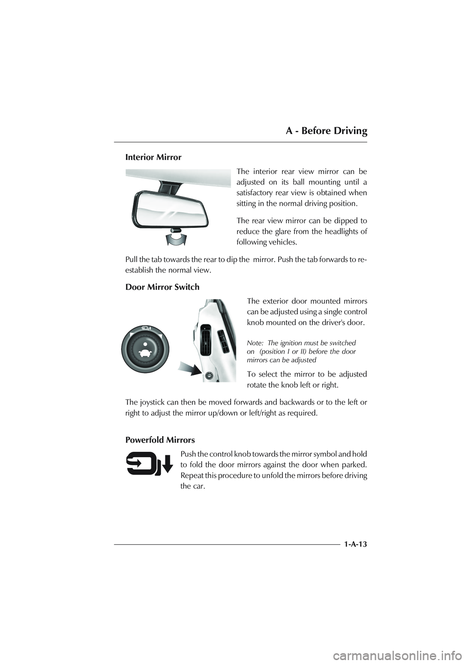
Interior Mirror
The interior rear view mirror can be
adjusted on its ball mounting until a
satisfactory rear view is obtained when
sitting in the normal driving position.
The rear view mirror can be dipped to
reduce the glare from the headlights of
following vehicles.
Pull the tab towards the rear to dip the mirror. Push the tab forwards to re-
establish the normal view.
Door Mirror Switch
The exterior door mounted mirrors
can be adjusted using a single control
knob mounted on the driver's door.
Note: The ignition must be switched
on (position I or II) before the door
mirrors can be adjusted
To select the mirror to be adjusted
rotate the knob left or right.
The joystick can then be moved forwards and backwards or to the left or
right to adjust the mirror up/down or left/right as required.
Powerfold Mirrors
Push the control knob towards the mirror symbol and hold
to fold the door mirrors against the door when parked.
Repeat this procedure to unfold the mirrors before driving
the car.
Page 49 of 279

B - Controls
1-B-13
Side and Headlight Switching
The left stalk collar has three positions that control the external running lights
of the vehicle: in the off position all external lights are off.
Rotating the collar to the first click (the side lamp symbol) switches on the
side lights, side marker lights, rear lights and registration plate lights (licence
plate lights).
Rotating to the second click position (the headlamp symbol) switches on the
headlight dipped beams in addition to the side, side marker, rear and
registration plate (licence plate) lights.
Main and Dipped Beam Switching
When the headlight dipped beams are switched on, they may be switched
to main beams by pushing the left stalk away from the steering wheel. Pulling
the left stalk back to its central position will switch the headlights back to
dipped beams.
Headlight Flashing
When all lights are off or when only the side lights are on, the headlight main
beams may be flashed by pulling the left stalk towards the steering wheel.
The headlights will go off when the stalk is released.
Page 70 of 279

C - Driving
1-C-5
The Ignition Lock
The Ignition Lock, located on the right side of the steering column, performs
the following functions:
• Steering Lock
• Ignition Switch
The switch has three positions:
Position OAll systems off, steering lock engaged.
Position IAuxiliaries on (e.g. radio), steering lock released. Use this
position if the vehicle is being towed.
Position IIIgnition and all other electrical systems on. This is the
normal running position.
Page 93 of 279

D - Heating, Ventilation & Air Conditioning
1-D-4
Door Mounted Vents
The door vents are also controllable and can be set to suit the occupants
requirements.
A lever at the top of each door vent controls the distribution and volume of
air.
In the mid position, unrestricted airflow is available from the door vent and
the side window vent.
Moving the lever towards the window symbol progressively closes off the
door vent and biases airflow to the side window vent.
Moving the lever towards the
•symbol progressively closes off the airflow
to both side window and door vents. This lever position may be used during
demist operations to ensure maximum airflow to the windscreen.
Page 102 of 279

E - Security Systems
1-E-3
System Operation - Basic Controls
The system is controlled using the two button key fob. The left (key symbol)
button controls the normal locking/unlocking of the car and arms/disarms
the alarm system. The right (boot open symbol) button controls the
unlocking of the boot. The Panic Alarm feature is operated using the left key
fob button.
The security system aerial is located at the rear of the car. The key fob should
be pointed towards this area of the vehicle to ensure a strong signal. The
normal operating range of the key fob is approximately 10 metres (30 feet).
The Passive Anti-Theft feature is fully automatic and is operated via a
transponder in the ignition key head which communicates with the engine
immobiliser circuits.
Page 103 of 279

E - Security Systems
1-E-4
Unlocking the Car, Disarming the Alarm
Point the key fob towards the rear window and press the left button once.
The following events will occur:
1. The green light on the key fob will light while the left button is pressed.
2. The car doors and fuel filler flap will unlock.
3. The direction indicators will flash (in markets where visible alarm signals
are permitted and programmed).
4. The alarm system will be switched off.
Locking the Car, Arming the Alarm
Point the key fob towards the rear window and press the left button. The
following events will occur:
1. The green light on the key fob will light while the left button is pressed.
2. The car doors and fuel filler flap will lock.
3. The direction indicators will flash once (in markets where visible alarm
signals are permitted).
4. The alarm system will be switched on.
Alarm and Security System Protection
With the alarm system armed, any attempt to open a door, the boot or the
bonnet will result in full alarm activation.
(See also the engine immobilisation protection afforded by the PATs system)
Page 127 of 279

F - Owner Maintenance
1-F-18
The Vehicle Toolkit
On vehicles fitted with a space-saver spare wheel , the tool kit is stored in
the spare wheel insert.
On vehicles without the spare wheel option the vehicle toolkit is stored in
a well within the boot floor and covered by a boot floor liner panel. The
standard toolkit consists of the following items:
• 2 Tyre Inflation Aerosols and Warning Labels
• 1 Tyre Pressure Gauge
• 1 Towing Eye
• 1 Pair of Pliers
• 1 Screwdriver
• 1 Pair of Gloves
• 1 Locking Wheelnut Socket (UK only)
• 1 Bulb and Fuse Kit
• 1 Allen Key
Lift up the boot floor to access the toolkit.