fuel ASTON MARTIN DB7 1997 Workshop Manual
[x] Cancel search | Manufacturer: ASTON MARTIN, Model Year: 1997, Model line: DB7, Model: ASTON MARTIN DB7 1997Pages: 421, PDF Size: 9.31 MB
Page 3 of 421
^?
Introduction
#
••t
*<;'..
Introduction '-^;^'^<-~'
^--"^^zfjj^^T^""
Workshop Manual Sections
The
DB7
Workshop Manual
is
divided .jnto,9seGtipnsE.a&foli
1 Engine
2.
Fuel,
Emission Control
and
Exhaust
3. Transmission
4.
Suspension
and
Steering
5. Brakes, Wheels
and
Tyres
6. Electrics
7. Chassis
and
Body
8.
Air
Conditioning
9. Aston Martin Diagnostic System
Procedure Numbering
The workshop manual procedures
are
numbered using
the
parts list numbers
as a key. The
first
two
digits
oi a
workshop manual procedure number
are
also
the
parts list number
(e.g.
1.5.01
Sump Removal relates
to PL 1.5 Oil
Pump
and
Sump). Thus when carrying
out a
procedure,
you can
quickly locate
the
relevant parts illustration
and
spare parts list.
To avoid excessive repetition, each procedure will
be
fully detailed once
in its
appropriate place
in the
manual.
In
any other location where this procedure
is
required,
it
will
be
referenced only
by its
title
and its
procedure number.
Special Tools
Where special service tools
are
required
to
perform
an
operation,
the
tool number
is
recorded
at the
point
of use
within
the
procedure.
An
index
and
illustrated list
is
provided
in
this section
for the
purpose
of
identifying special
tools.
References
References
to the
left, right, front
or
rear
of
the vehicle
or of
a component
are
always made as
if
sitting
in the
drivers
seat facing forward.
Any
such references
to
assemblies removed from
the
vehicle
are to the
normal orientation
of
the assembly when fitted
in the
vehicle.
Repairs
and
Replacements
Where replacement parts
are
required,
it is
essential that only genuine Aston Martin parts
are
used. Your attention
is drawn
to the
following points concerning repairs
and the
fitting
of
genuine Aston Martin parts
and
accessories:
• Safety features embodied
in the
vehicle
may be
impaired
if
other than genuine Aston Martin parts
are
fitted.
In certain territories, legislation prohibits
the
fitting
of
parts which
are not
produced
to the
manufacturers
specification.
• Adhere
to
torque wrench settings given
in
this manual.
• Locking devices, where specified, must
be
fitted.
If the
efficiency
of a
locking device
is
impaired during
removal,
it
must
be
renewed.
•
The
vehicle warranty
may be
invalidated
by the
fitting
of
other than genuine Aston Martin parts.
April
1997 Hi
Page 4 of 421
Introduction
/^r"^^^^^3^
'"'P ?
Safety Precautions L —^ ^^—^
Safety Precautions "
All service workshops are a source of potential danger and repair work should only be performed by technically
trained staff following the procedures in this manual. A safety conscious approach to the performance of all service
procedures must be observed at all times. Statutory requirements governing all aspects of health and safety at work
including directives for the proper use of materials and equipment must be implemented.
The following contains a list of particular safety precautions which should be observed; it is not intended to be
exhaustive.
Air Conditioning System
Do not disconnect any air conditioning refrigerant system pipes unless trained and instructed to do
so.
The refrigerant
used can cause blindness if allowed to contact your eyes.
Chemical Handling and Storage
Chemicalsusedintheservicingofmotorvehiclesincludeacids,adhesives, antifreeze, brake fluids, coolants, grease,
oil,
paint, resin and solvents. Exposure to certain chemicals through direct contact or inhalation can be
fatal.
Potential hazards may also be present through the incorrect use, storage and handling of chemicals causing a fire
risk. The following precautions should be observed.
1.
Strictly adhere to handling and safety information found on containers and labels.
2.
Do not store chemicals in unlabelled or incorrectly labelled containers.
3. Containers used for storing chemicals should not be left
open;
there is a risk of
spilling,
or evaporation of fumes
which may be inflammable or toxic.
4.
Do not mix chemicals unless instructed to do so following manufacturers guidelines.
5. Do not inhale chemical materials to determine identity, they may be toxic.
6. Do not use petrol, kerosene, diesel
fuel,
gas oil, thinners or solvents for washing
skin.
7. Containers whose capacity is over 25 litres (5 gallons) require a bund wall in order to contain spillages.
8. Chemicals based on solvents such as paint should not be sprayed in a confined space; work areas used for
such operations should be well ventilated and fume extraction equipment should be utilised.
9. Ensure that adequate ventilation is provided when volatile de-greasing agents are being used.
WARNING: Fume extraction equipment must be in operation when
solvents
are
used
e.g.
trichloroethane, white
spirit, SBP3, methylene chloride, perchlorethylene.
WARNING: Do not smoke in the vicinity of volatile de-greasing agents.
10.
Avoid splashing the
skin,
eyes and clothing.
11.
Clean chemicals from the skin and clothing as soon as possible after soiling.
12.
Wear protective clothing such as goggles, non porous gloves and apron when hand
I
ing battery acid and other
corrosive and toxic substances.
iv April 1997
Page 5 of 421
//—-^
^^^^5~^
' -^ ^ Introduction
Safety Precautions
Safety Precautions (continued)
Electrical Equipment
1.
Ensure that electrical equipment is in safe working order before use.
2.
Inspect power leads of all mains electrical equipment for damage and security, and check that it is properly
earthed.
3. Ensure that electrical equipment is protected by a fuse of the correct current rating.
4.
Disconnect the battery before commencing repair operations to the electrical system, fuel system and engine
or when working beneath the vehicle.
Exhaust Fumes
Engines should not be run in confined spaces, exhaust fumes contain harmful and toxic substances including carbon
monoxide which can prove fatal if inhaled. Engines must only be run where there is fume extraction equipment in
operation or where there is adequate ventilation.
Fire Precautions
1.
Ensure that a suitable form of fire extinguisher is conveniently located near the work area.
2.
Keep oils, solvents and combustible materials away from naked flames and other sources of ignition.
3. Ensure that NO SMOKING signs are posted around areas where combustible materials and vapour may be
present and ensure that the warnings are strictly observed.
4.
Ensure that dry sand is available to soak up any spillage of fuel or other flammable solutions.
5. Fume extraction equipment must be available and in full working order to remove combustible and toxic
vapours.
6. All personnel should be aware of the fire drill procedures and precautions.
Jacking and Lifting
1.
The recommended procedures for lifting, jacking and towing are included latefin this seetion-and must be
strictly observed to ensure personal safety.
2.
Always use a vehicle hoist, ramp or pit for working beneath the car in preferencetd^&^cking
3. Never rely on a jack to support a car independently, use axle stands or blocks carefully pJaQed at the jacking
points to provide rigid support.
4.
When working beneath a vehicle, chock the wheels as well as applying the handbrake.
5. Ensure that the vehicle is standing on firm level ground before jacking or lifting.
5. Check any lifting equipment used has adequate capacity for the load being lifted and is ih"fdll working order.
Tools and Equipment
1.
Do not leave tools, equipment, spilt oil, etc. around or on the work area.
2.
Ensure that tools and equipment used are in good condition; do not use damaged or defective tools or
equipment.
3. Do not apply heat in an attempt to free stiff nuts or fittings; as well as causing damage to protective coatings,
there is a risk of damage to electronic equipment and brake lines from stray heat.
4.
Use the recommended service tool where instructed to do so.
April 1997 v
Page 6 of 421
Introduction //—">) ^nir>^ ' ^ 1
Safety Precautions L 1 .^—y^
Safety Precautions (continued)
Used Engine Oil
Prolonged and repeated contart with mineral oil will result in the removal of natural fats from the
skin,
leading to
dryness, irritation and dermatitis. In addition, used engineoii contains potentially harmful contaminants which may
cause skin cancer. Adequate means of skin protection and washing facilities should be provided.
Health protection precautions:
1.
Avoid prolonged and repeated contact with oils, particularly used engine oil.
2.
Wear protective clothing, including impervious gloves where practicable.
3. Do not put oily rags in pockets.
4.
Avoid contaminating clothes with oil.
5. Overalls must be cleaned regularly. Discard unwashable clothes and oil impregnated footwear.
6. First aid treatment should be obtained immediately for open cuts or wounds.
7. Use barrier creams, apply before each work period to help the removal of oil from the
skin.
8. Wash with soap and water to ensure all oil is removed. Preparations containing lanolin replace the natural
skin oils which have been removed.
9. Do not use petrol, kerosene, diesel
fuel,
gas oil, thinners or solvents for washing
skin.
10.
If skin disorders develop, obtain medical advice.
11.
Where practicable, degrease components prior to handling.
12.
Where there is a risk of eye contact, eye protection should be worn, in addition, an eyewash facility should
be provided.
Environmental Protection
It is illegal to pour used oil on the ground, down sewers or drains, or into water courses. The burning of used engine
oil in small space heaters or boilers is not recommended unless emission control equipment is
fitted;
in case of doubt,
contact the Local Authority for advice on disposal facilities.
vi April 1997
Page 21 of 421
3^?
Electrics
Rear Lamp Cluster / Central Locking System / Door Lock Motors
6.7.02 Rear Lamp Cluster Door Mounted Components
Procedure
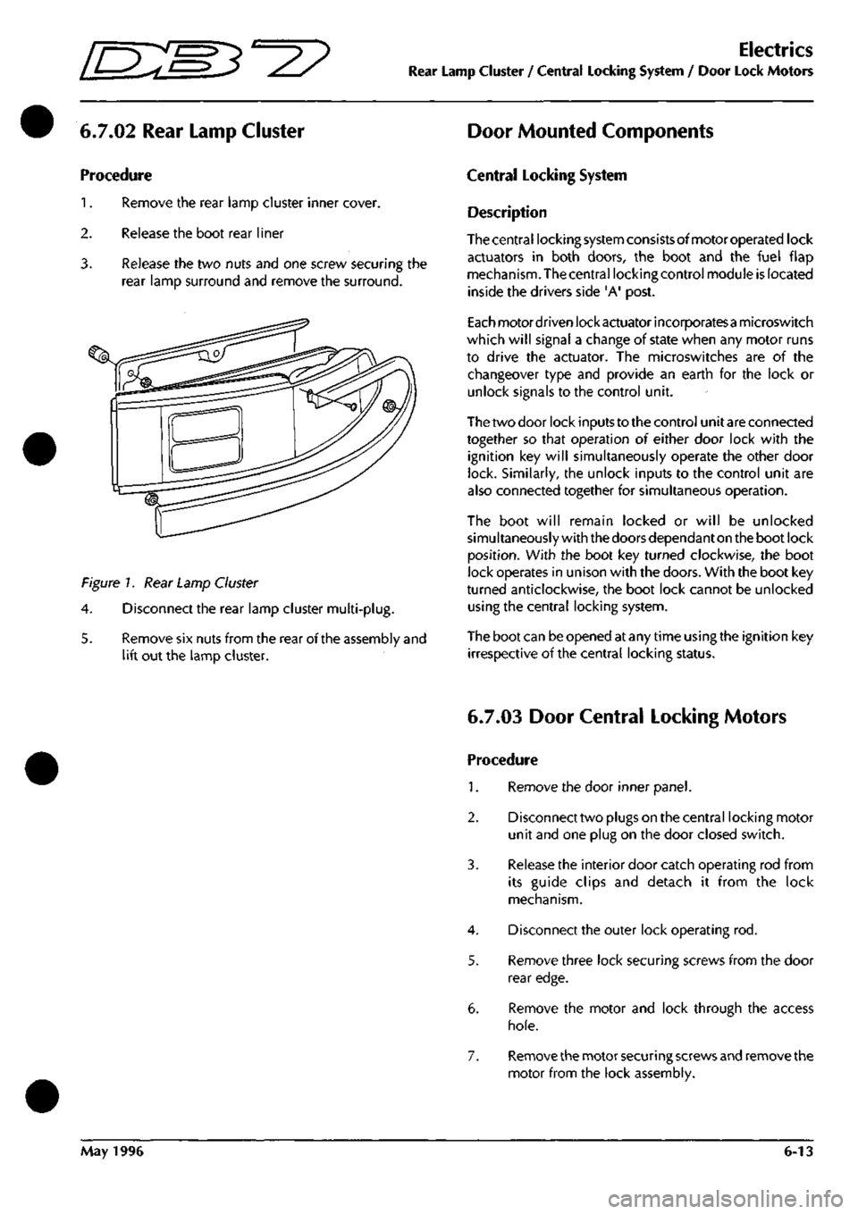
1.
Remove the rear lamp cluster inner cover.
2.
Release the boot rear liner
3. Release the two nuts and one screw securing the
rear lamp surround and remove the surround.
Figure 7. Rear Lamp Cluster
4.
Disconnect the rear lamp cluster multi-plug.
5. Remove six nuts from the rear of the assembly and
lift out the lamp cluster.
Central Locking System
Description
Thecentral locking system consistsofmotoroperated lock
actuators in both doors, the boot and the fuel flap
mechanism. The central locking control module is located
inside the drivers side 'A' post.
Each motordriven lock actuator incorporatesa microswitch
which will signal a change of state when any motor runs
to drive the actuator. The microswitches are of the
changeover type and provide an earth for the lock or
unlock signals to the control unit.
The two door lock inputs to the control unit are connected
together so that operation of either door lock with the
ignition key will simultaneously operate the other door
lock. Similarly, the unlock inputs to the control unit are
also connected together for simultaneous operation.
The boot will remain locked or will be unlocked
simultaneously with the doors dependant on the boot lock
position.
With the boot key turned clockwise, the boot
lock operates in unison with the doors. With the boot key
turned anticlockwise, the boot lock cannot be unlocked
using the central locking system.
The boot can be opened at any time using the ignition key
irrespective of the central locking status.
6.7.03 Door Central Locking Motors
Procedure
1.
Remove the door inner panel.
2.
Disconnect two plugs on the central locking motor
unit and one plug on the door closed switch.
3. Release the interior door catch operating rod from
its guide clips and detach it from the lock
mechanism.
4.
Disconnect the outer lock operating rod.
5. Remove three lock securing screws from the door
rear edge.
6. Remove the motor and lock through the access
hole.
7. Remove the motor securing screws and remove the
motor from the lock assembly.
May 1996 6-13
Page 28 of 421
Electrics
Electrical Component Location Index •
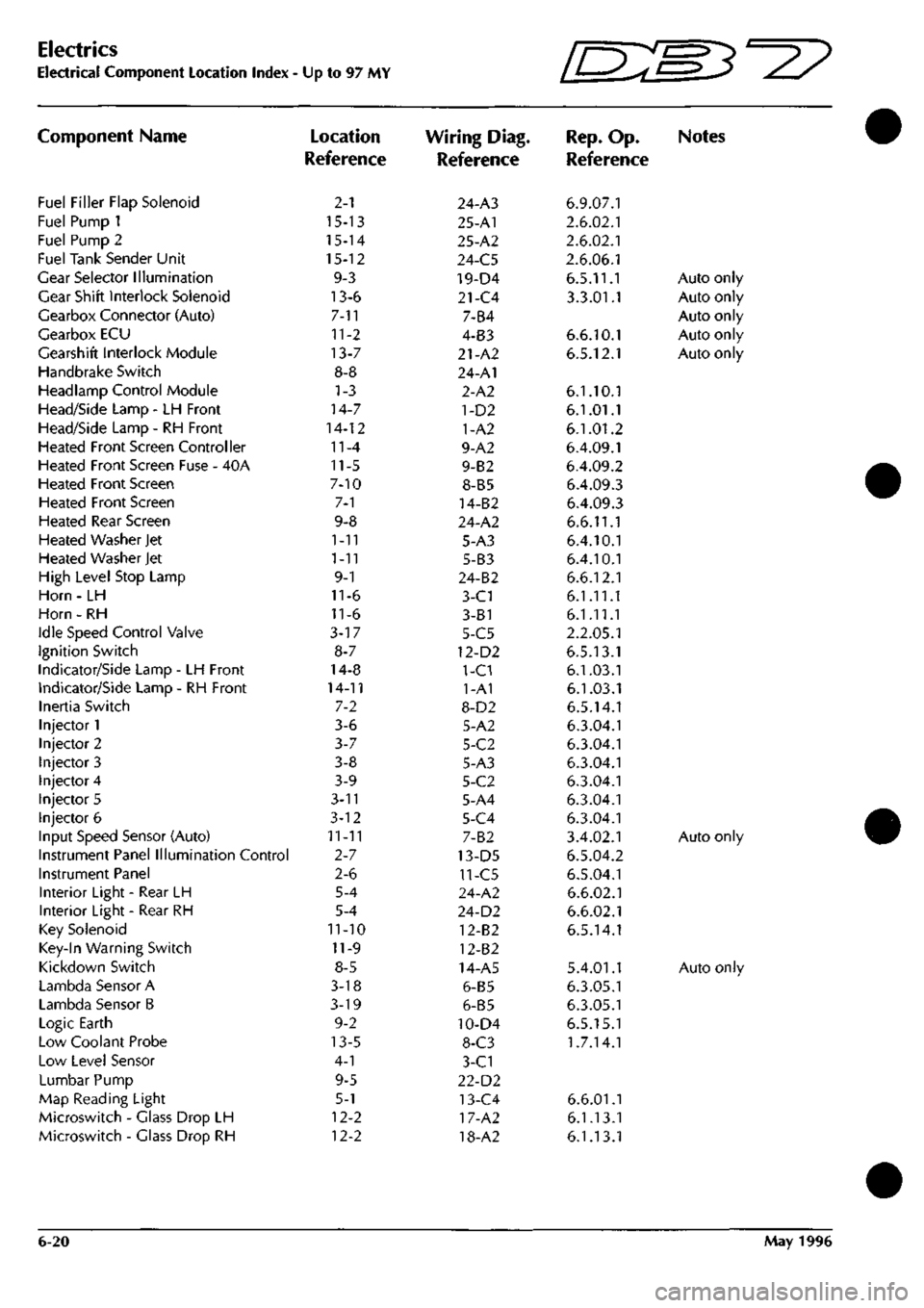
Component Name
Fuel Filler Flap Solenoid
Fuel Pump 1
Fuel Pump 2
Fuel Tank Sender Unit
Gear Selector Illumination
Gear Shift Interlock Solenoid
Gearbox Connector (Auto)
Gearbox ECU
Gearshift Interlock Module
Handbrake Switch
Headlamp Control Module
Head/Side Lamp - LH Front
Head/Side Lamp - RH Front
Heated Front Screen Controller
Heated Front Screen Fuse - 40A
Heated Front Screen
Heated Front Screen
Heated Rear Screen
Heated Washer Jet
Heated Washer Jet
High Level Stop Lamp
Horn - LH
Horn - RH
Idle Speed Control Valve
Ignition Switch
Indicator/Side Lamp - LH Front
Indicator/Side Lamp - RH Front
Inertia Switch
Injector 1
Injector 2
Injector 3
Injector 4
Injector 5
Injector 6
Input Speed Sensor (Auto)
Instrument Panel Illumination Control
Instrument Panel
Interior Light - Rear LH
Interior Light - Rear RH
Key Solenoid
Key-In Warning Switch
Kickdown Switch
Lambda Sensor A
Lambda Sensor B
Logic Earth
Low Coolant Probe
Low Level Sensor
Lumbar Pump
Map Reading Light
Microswitch - Glass Drop LH
Microswitch - Glass Drop RH
Up to 97 MY
Location
Reference
2-1
15-13
15-14
15-12
9-3
13-6
7-11
11-2
13-7
8-8
1-3
14-7
14-12
11-4
11-5
7-10
7-1
9-8
1-11
1-11
9-1
11-6
11-6
3-17
8-7
14-8
14-11
7-2
3-6
3-7
3-8
3-9
3-n
3-12
11-11
2-7
2-6
5-4
5-4
11-10
11-9
8-5
3-18
3-19
9-2
13-5
4-1
9-5
5-1
12-2
12-2
Wiring Diag.
Reference
24-A3
25-A1
25-A2
24-C5
19-D4
21-C4
7-B4
4-B3
21-A2
24-A1
2-A2
1-D2
1-A2
9-A2
9-B2
8-B5
14-B2
24-A2
5-A3
5-B3
24-B2
3-C1
3-81
5-C5
12-D2
1-C1
1-A1
8-D2
5-A2
5-C2
5-A3
5-C2
5-A4
5-C4
7-B2
13-D5
11-C5
24-A2
24-D2
12-B2
12-B2
14-A5
6-B5
6-B5
10-D4
8-C3
3-C1
22-D2
13-C4
17-A2
18-A2
Ini^'
IL-^^'^
Rep.
Op.
Reference
6.9.07.1
2.6.02.1
2.6.02.1
2.6.06.1
6.5.11.1
3.3.01.1
6.6.10.1
6.5.12.1
6.1.10.1
6.1.01.1
6.1.01.2
6.4.09.1
6.4.09.2
6.4.09.3
6.4.09.3
6.6.11.1
6.4.10.1
6.4.10.1
6.6.12.1
6.1.11.1
6.1.11.1
2.2.05.1
6.5.13.1
6.1.03.1
6.1.03.1
6.5.14.1
6.3.04.1
6.3.04.1
6.3.04.1
6.3.04.1
6.3.04.1
6.3.04.1
3.4.02.1
6.5.04.2
6.5.04.1
6.6.02.1
6.6.02.1
6.5.14.1
5.4.01.1
6.3.05.1
6.3.05.1
6.5.15.1
1.7.14.1
6.6.01.1
6.1.13.1
6.1.13.1
W3^y
Notes
Auto only
Auto only
Auto only
Auto only
Auto only
Auto only
Auto only
6-20 May 1996
Page 29 of 421
[n:m3^y
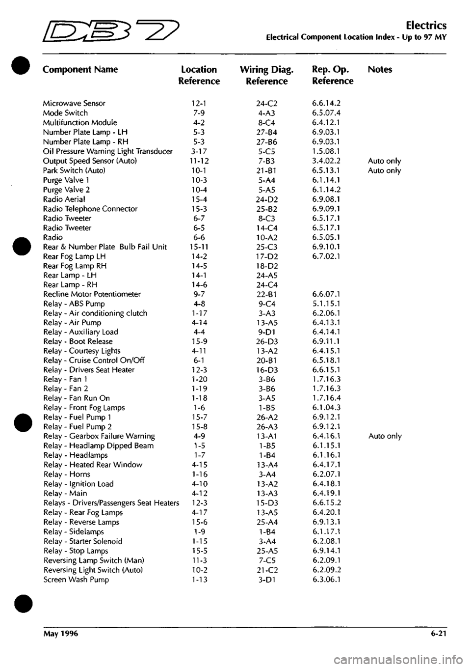
Component Name
Microwave Sensor
Mode Switch
Multifunction Module
Number Plate Lamp - LH
Number Plate Lamp - RH
Oil Pressure Warning Light Transducer
Output Speed Sensor (Auto)
Park Switch (Auto)
Purge Valve 1
Purge Valve 2
Radio Aerial
Radio Telephone Connector
Radio Tweeter
Radio Tweeter
Radio
Rear & Number Plate Bulb Fail Unit
Rear Fog Lamp LH
Rear Fog Lamp RH
Rear Lamp - LH
Rear Lamp - RH
Recline Motor Potentiometer
Relay - ABS Pump
Relay - Air conditioning clutch
Relay - Air Pump
Relay - Auxiliary Load
Relay - Boot Release
Relay - Courtesy Lights
Relay - Cruise Control On/Off
Relay - Drivers Seat Heater
Relay - Fan 1
Relay - Fan 2
Relay - Fan Run On
Relay - Front Fog Lamps
Relay - Fuel Pump 1
Relay - Fuel Pump 2
Relay - Gearbox Failure Warning
Relay - Headlamp Dipped Beam
Relay - Headlamps
Relay - Heated Rear Window
Relay - Horns
Relay - Ignition Load
Relay - Main
)
Location
Reference
12-1
7-9
4-2
5-3
5-3
3-17
11-12
10-1
10-3
10-4
15-4
15-3
6-7
6-5
6-6
15-11
14-2
14-5
14-1
14-6
9-7
4-8
1-17
4-14
4-4
15-9
4-11
6-1
12-3
1-20
1-19
1-18
1-6
15-7
15-8
4-9
1-5
1-7
4-15
1-16
4-10
4-12
Relays - Drivers/Passengers Seat Heaters 12-3
Relay - Rear Fog Lamps
Relay - Reverse Lamps
Relay - Sidelamps
Relay - Starter Solenoid
Relay - Stop Lamps
Reversing Lamp Switch (Man)
Reversing Light Switch (Auto)
Screen Wash Pump
4-17
15-6
1-9
1-15
15-5
11-3
10-2
1-13
Electrics
Electrical Component Location Index - Up to 97 MY
Wiring Diag.
Reference
24-C2
4-A3
8-C4
27-84
27-B6
5-C5
7-B3
21-B1
5-A4
5-A5
24-D2
25-B2
8-C3
14-C4
10-A2
25-C3
17-D2
18-D2
24-A5
24-C4
22-81
9-C4
3-A3
13-A5
9-D1
26-D3
13-A2
20-B1
16-D3
3-B6
3-B6
3-A5
1-B5
26-A2
26-A3
13-A1
1-B5
1-84
13-A4
3-A4
13-A2
13-A3
15-D3
13-A5
25-A4
1-B4
3-A4
25-A5
7-C5
21-C2
3-D1
Rep.
Op. Notes
Reference
6.6.14.2
6.5.07.4
6.4.12.1
6.9.03.1
6.9.03.1
1.5.08.1
3.4.02.2
Auto only
6.5.13.1
Auto only
6.1.14.1
6.1.14.2
6.9.08.1
6.9.09.1
6.5.17.1
6.5.17.1
6.5.05.1
6.9.10.1
6.7.02.1
6.6.07.1
5.1.15.1
6.2.06.1
6.4.13.1
6.4.14.1
6.9.11.1
6.4.15.1
6.5.18.1
6.6.15.1
1.7.16.3
1.7.16.3
1.7.16.4
6.1.04.3
6.9.12.1
6.9.12.1
6.4.16.1
Auto only
6.1.15.1
6.1.16.1
6.4.17.1
6.2.07.1
6.4.18.1
6.4.19.1
6.6.15.2
6.4.20.1
6.9.13.1
6.1.17.1
6.2.08.1
6.9.14.1
6.2.09.1
6.2.09.2
6.3.06.1
May 1996 6-21
Page 97 of 421
I NO COLOUR AlttA 1503 BW CI
H/BRAKE.
ISWITCH I
HO COLOUR 5 YS 175 PY 259 OR 260 0 261 NR 4T4 YO 475 B 476 BR 479 s 481 B 482 BR 483 LCK 484 RIN 486 RN 487 GR 489 UIN 491 W 492 rw
493
KB
494
BR
495
OR
495
OU
497
SLG
500
KB
501
GB
503
BW
504
GW
505
LGO
506
OW
507
GP
509
OG
829
NO
833
PS
834
NS
835
NY
836
U
841
P
842
PK
850
P
851
PK
855
HP
858
RU
872
BRO
973
HP
975
RU
89J
R
894
WS
896
R
897
WS
902
G
904
0
907
WK
930
WK
AREA
B6 B6 86 86 B6 02 B2 B2 86 C2 C2 B6 A4 Dl
B2-I8I
A4 B6 B6 B6 86 Be 66 B6 B6 B6 Al
C2-I87
C5 A3 B6 A3 B6 B6 B6 C6
C2-185
A3 A3 Dl Dl C4 D4 A4 A5 85 BG B6 86 Be B6 B6 B6 86
HO COLOUR
839 B 840 B
TBtr
B4-I8;
NO COLOUR PIN ARE!" 508 OG I CI 506 OW J a FUEL FILLER FLAP
N6
tbim AREA
873
HP CI
874
BR
C3-I9I
INTERIOR LIGHT
NO COLOUR
PIH
841
P I
842
PK 2
CI
ja
JHEATEC
|BACKLI
J
HEATED
I
BACKLIGHT
I
NO
COLOUR AREA
I
ll>13
B
Ag-I8?l
NO COLOUR
PIN
872
BRD 1
484
RIN 2
W
UIN J
AREA
CI 81 Bl
,
BOOT LAMP,
r^
NO COLOUR
PIN
I
844 B 2
845
CP 3
TBET
A2-I82 C6
LH REAR LAMP
NO COLOUR
PIN
875
RU
876
GN
877
GR
878
B
879
RS
880
GP
1 2 3 4 5 _6
AREA
a
C3-I9C B2-I8I B4-I8; B4-I8<
BG LH
SIDEMARKER
^
HO COLOUR
PIN
JRET
476
BR I Bl
47?
6 i B!
HO COLOUR
PIH
870
RS I
671
B 2_
AREA B4-I8'
SUM
NO
C6L6UD
i^iti
SEET
846 NS I Ce
847
NY 2 C6 848 \l i
C2-I85
(^
482
BR I W i 2_
TSfT
-0 H—— S NO COLOUR 849 TIN AREA JS_J
NO COLOUR AREA 854
BR
C3-I9I 855
HP CI
I BOOT LAMP,
SPL
189
SPL
192
NO COLOUR 865
BR
866
PG
867
RS
868
RG m B
PIN 1 2 3 4 5 6 7
9
.
ARtA C3-I9I 06
ce
03-189 C5-ieB
NO
t6L6ul)
5 YS 175 PY 259 OR 260 0 261 NR 483 LGK 479 S 491 W 492 YW 493 KB 494 8R 495 OR 496 OU 497 SLG 500 KB 901 GB 507 GP 629 NO 833 PS 834 NS 835 NY 845 GP 846 NS 847 NY 849 TIN 852 P 863 GP 866 PG 867 RS
-mr Bl Bl Bl Bl Bl Bl Bl ei Bl Bl Bl Bl Bl Bl CI CI CI CI CI a CI 82 B2 C2 C2 02 04 C5 C5
•w 880 «B5 889 890 891 893 894 896 897 900 902 904 907 918 927 930 932 933 936 939 941
-mem
GP B BR 8 B R WS R WS GH 6 G WK R6 BRD WK GW GR U B RS
-ARIT
86
C5-I92 C3-I9I C5-I92 D2-I68
CI a CI 01
C3-I9C
01 Dl Dl
c3-ies
C2-I86 Dl 0-187 B2-I8I C2-I65 C5-192 C4-I84
RH REAR
LAI*
(5
Dl 05 0 Q B 0
SHEET
27
AREA
C5
.» ^
NO COLOUR AREA 505
LGO CI
'_S C5H92
J
FUEL
I
SENDi
-t
1
FUEL TANK
'
SENDER UNIT
NO COLOUR
PIN
858
RU
859
CN
860
GW
861
8
862
RG
Ki
?F
1 2 3 4 5
.._6_
AREA
CI
C5-I9C C2-I87 02-188 D5-I89
«
INTERIOR! 'LIGHT
I
•HEATED BACKLIGHT'
I
NO
COLOUR i486
RN
AREA 81 HO COLOUR
PIN
AREA
850 P I CI
851
PK 2 CI
NO COLOUR
PIN
I
852
P
474
YG
^ii_
C6 Bl
lK^^2
RH SIDEMARKER NO COLOUR
PIN
AREA 856
RG I
D3-IS9 657
B 2 E2:
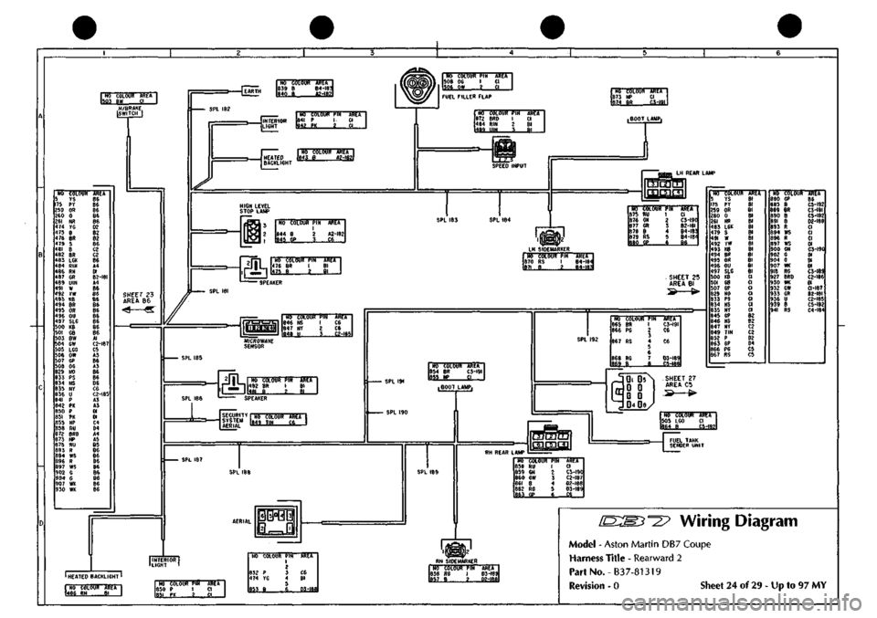
Wiring Diagram
Model - Aston Martin DB7 Coupe
Harness Title - Rearward 2
PartNo.-B37-81319
Revision - 0 Sheet 24 of 29 - Up to 97 MY
Page 101 of 421
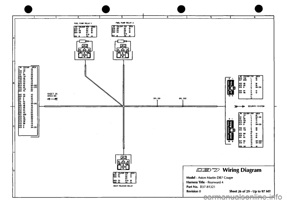
FUEL PUMP RELAY
1
NO COLOUC 260
0
922
KB
884
m
916
N
PIN
AI^CA
89
Bl
86
Bl
87
Bl
e7A SO
CI
FUEL PUMP RELAY
2
m
itLoUl!
tm
259
OR 85
923
KB 86
882
UG 87
87A 917
N SO
km Bl a Bl
.,?!
[M]
rCZK>»—1
HO COLOUR
5
rs
259
OR
260
0
261
NR
492
YW
493
KB 495 OR 496 OU 829 NO 834 N5 846 NS 849 TIN 866 PS
882
UG
884
UR
916
H
917 919 921 922
KB
923
KB
924
NY
925
PS
926
PS
927
BRD
929
NY 930 m 932 GW
933
GR 935 BR 936 U 939 B
C6
A3 A2
86 C6 B6
C6
C6 C6
B4-202
84-202
B6 03
A3 A2 A2 A3
C6
B4-202
A2 A3 03 03 03
86 86 86 C6 C6 C6 C6
B4-20I
SPL
202
M6
cbmk pld
849
TIN
927
BRD
493
KB
829
NO
928
B •
929
NY
930
WK
1 2 3 4 5 6 7 8 9 10 II 12
Uih Bl CI
Bl Bl B4-20I
CI CI
SECURITY SYSTEM
NO COLOUI 5
YS
931
B
261
NR
932
GW
953
GR
934
B
496
OU
492
YW
935
BR
936
U
919
NS
937
NS
938
B
495
OR
PIN 1 ? 3 4 5 6 7 8 9 10 II 12 13 14 15 16 17
J?...
AREA Bl B4-20I Bl CI CI B4-20I
Bl Bl
CI CI Bl
B4-202
84-201
Bl
I Is?""—I
NO COLOUR
PIN
924
NY 85
925
PS 86
87 866
PG 87A
926
PS 30
-mr Cl CI
Bl CI
BOOT RELEASE RELAY
Wiring Diagram
Model
-
Aston Martin
DB7
Coupe
Harness Title
-
Rearward
4
Part
No.
B37-81321
Revision
0
Sheet
26 of 29 - Up to 97 MY
Page 109 of 421
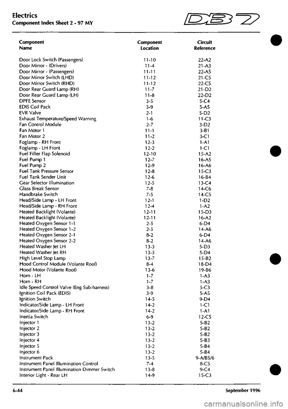
Electrics
Component Index Sheet 2 - 97 MY
Component
Name
Door Lock Switch (Passengers)
Door Mirror - (Drivers)
Door Mirror - (Passengers)
Door Mirror Switch (LHD)
Door Mirror Switch (RHD)
Door Rear Guard Lamp (RH)
Door Rear Guard Lamp (LH)
DPFE Sensor
EDIS Coil Pack
EVR Valve
Exhaust Temperature/Speed Warning
Fan Control Module
Fan Motor 1
Fan Motor 2
Foglamp - RH Front
Foglamp - LH Front
Fuel Filler Flap Solenoid
Fuel Pump 1
Fuel Pump 2
Fuel Tank Pressure Sensor
Fuel Tank Sender Unit
Gear Selector Illumination
Glass Break Sensor
Handbrake Switch
Head/Side Lamp - LH Front
Head/Side Lamp - RH Front
Heated Backlight (Volante)
Heated Backlight (Voiante)
Heated Oxygen Sensor
1
-1
Heated Oxygen Sensor
1
-2
Heated Oxygen Sensor 2-1
Heated Oxygen Sensor 2-2
Heated Washer Jet LH
Heated Washer Jet RH
High Level Stop Lamp
Hood Control Module (Volante Roof)
Hood Motor (Volante Roof)
Horn - LH
Horn - RH
Idle Speed Control Valve (Eng Sub-harness)
Ignition Coil Pack (EDIS)
Ignition Switch
Indicator/Side Lamp - LH Front
Indicator/Side Lamp - RH Front
Inertia Switch
Injector 1
Injector 2
Injector 3
Injector 4
Injector 5
Injector 6
Instrument Pack
Instrument Panel Illumination Control
Instrument Panel Illumination Dimmer Switch
Interior Light - Rear LH
6-44
Component
Location
11-10
n-4
11-11
11-12
11-12
11-7
11-8
3-5
3-9
2-1
1-6
2-7
11-1
11-2
12-3
12-2
12-10
12-7
12-9
12-8
12-6
12-5
7-8
7-5
12-1
12-4
12-11
12-11
2-5
2-5
8-2
8-2
13-3
13-3
13-7
8-4
13-6
1-7
1-7
3-8
3-9
14-5
14-2
14-2
6-9
13-2
13-2
13-2
13-2
13-2
13-2
13-5
7-4
13-8
14-9
fEB^-^?
Circuit
Reference
22-A2
21-A3
22-A5
21-C5
22-C5
21-D2
22-D2
5-C4
5-A5
5-D2
11-C3
3-D2
3-B1
3-C1
1-A1
1-C1
15-A2
16-A5
16-A6
15-C3
16-B4
13-C4
14-C6
14-C5
1-D2
1-A2
15-D3
16-A2
6-D4
14-A6
6-D4
14-A6
5-D3
5-D4
15-82
18-D4
19-B6
1-A3
1-A3
5-C3
5-A5
9-D4
1-C1
1-A1
12-C5
5-B2
5-B2
5-B2
5-B3
5-B4
5-B4
9-A/B5/6
8-C5
9-C4
15-C3
September 1996