adding oil ASTON MARTIN DB7 1997 Workshop Manual
[x] Cancel search | Manufacturer: ASTON MARTIN, Model Year: 1997, Model line: DB7, Model: ASTON MARTIN DB7 1997Pages: 421, PDF Size: 9.31 MB
Page 278 of 421

in:!M3^^?
Air Conditioning
Contents
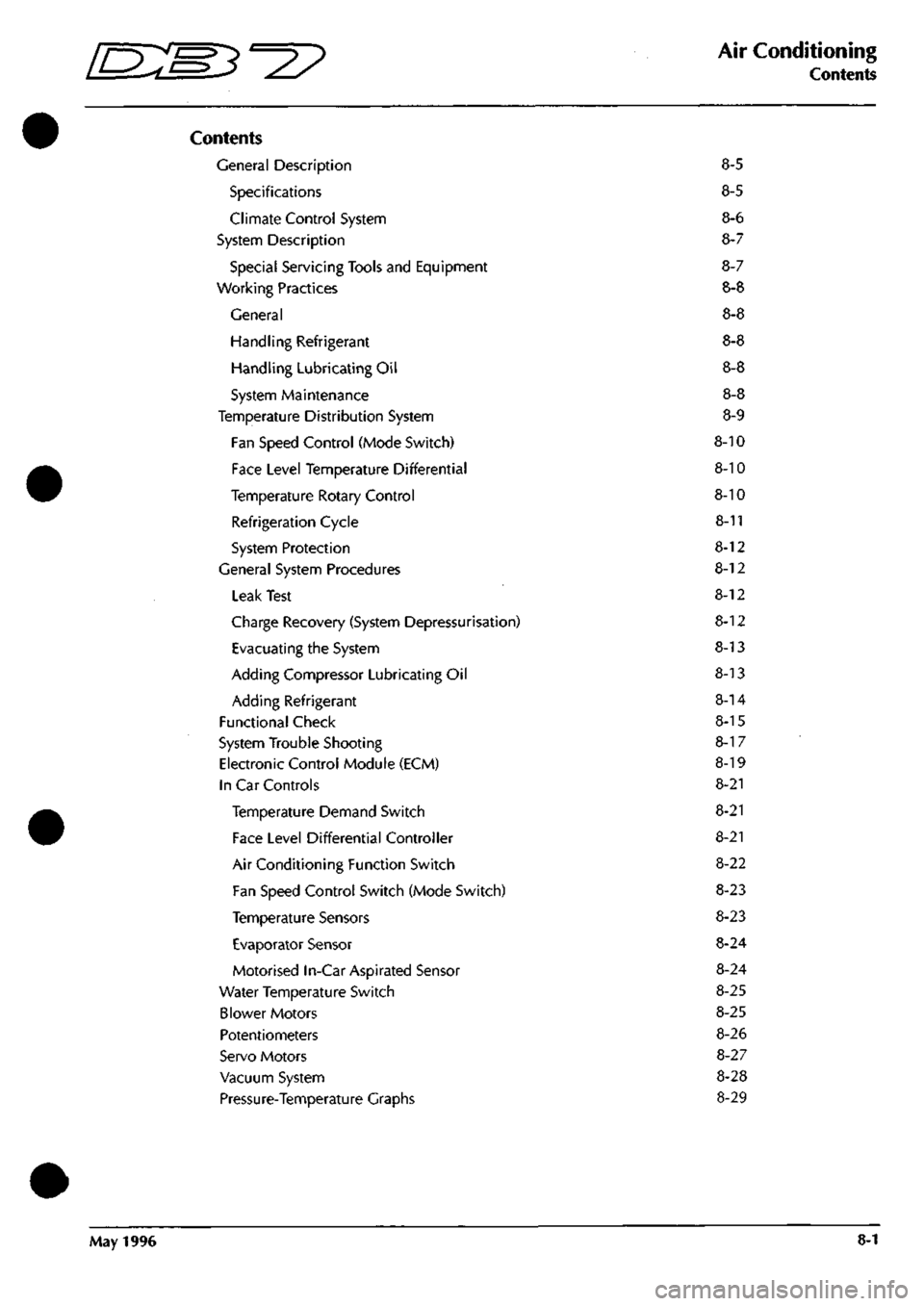
Contents
General Description 8-5
Specifications 8-5
Climate Control System 8-6
System Description 8-7
Special Servicing Tools and Equipment 8-7
Working Practices 8-8
General 8-8
Handling Refrigerant 8-8
Handling Lubricating Oil 8-8
System Maintenance 8-8
Temperature Distribution System 8-9
Fan Speed Control (Mode Switch) 8-10
Face Level Temperature Differential 8-10
Temperature Rotary Control 8-10
Refrigeration Cycle 8-11
System Protection 8-12
General System Procedures 8-12
Leak Test 8-12
Charge Recovery (System Depressurisation) 8-12
Evacuating the System 8-13
Adding Compressor Lubricating Oil 8-13
Adding Refrigerant 8-14
Functional Check 8-15
System Trouble Shooting 8-1 7
Electronic Control Module (ECM) 8-19
In Car Controls 8-21
Temperature Demand Switch 8-21
Face Level Differential Controller 8-21
Air Conditioning Function Switch 8-22
Fan Speed Control Switch (Mode Switch) 8-23
Temperature Sensors 8-23
Evaporator Sensor 8-24
Motorised In-Car Aspirated Sensor 8-24
Water Temperature Switch 8-25
Blower Motors 8-25
Potentiometers 8-26
Servo Motors 8-27
Vacuum System 8-28
Pressure-Temperature Graphs 8-29
May 1996 8-1
Page 290 of 421

^2?
Air Conditioning
General System Procedures
Evacuating the System
This process, the removal of unwanted air and moisture, is critical to the correct operation of the air conditioning
system.
The procedures depends on the characteristics of the recovery-recycle-recharge equipment and must be
carried out exactly in accordance with the manufacturers instructions.
Moisture can be highly destructive and may cause internal blockages due to freezing, but more importantly, water
suspended in the PAG oil will damage the compressor. Once the system has been opened for repairs, or the
refrigerant charge recovered, all traces oi moisture must be removed before recharging with new or recycled
refrigerant.
Adding Compressor Lubricating Oil
Oil can be added by three methods, two of which are direct into the system
• via the recovery-recycle-recharge station
• by proprietary oil injector.
Equipment manufacturer's instructions must be adhered to when using direct oil introduction.
The third method may be required because of rectification work to the existing compressor, or the need to fit a new
compressor. From an existing compressor, drain the oil into a measuring cylinder and record the amount. Flush the
unit out with fresh PAG oil and drain thoroughly. Refill the compressor with the same amount of PAG oil that was
drained out originally and plug all orifices immediately ready for refitting to the vehicle. The transit lubricating oil
must be drained and discarded from a new compressor before it may be fitted. An adjustment should be made to
the system oil level by taking into account:
• the quantity found in the original compressor
• the quantity deposited in the recovery equipment oil separator from the charge recovery operation.
Typically, 80 ml can be drained from the original compressor and 30 ml found in the oil separator; the sum of these
volumes (80 + 30 = 110 ml) is the amount of fresh PAG oil that must be put into the new compressor prior to fitting.
Hote:
The
discrepancy
between
this
figure
and
the
nominal capacity of
135
ml is
caused
by normally not
recoverable
oil being
trapped in
components
such
as
the receiver-drier or
evaporator.
The above statements are only true if there is no evidence of a leak. Where a leak has been detected and rectified,
the compressor must be refilled with the specified quantity.
Caution: Always decant
fresh
oil from a sealed container and do not leave oil exposed to the
atmosphere.
PAG oil is very
hygroscopic
(absorbs
water) and rapidly
attracts
atmospheric moisture.
PAG oil must
NEVER
be mixed with mineral
based
oils.
Do not
reuse
oil following a recovery cycle,
dispose
of it
safely.
Depending on the state of the air conditioning system immediately prior to charge recovery and the rate of recovery,
an amount of oil is drawn out with the refrigerant. The quantity is approximately 30 to 40 mi; this may vary, and
the figure is given only for guidance. It is most important that the oil separator vessel in the recovery equipment is
clean and empty at the start of the process so that the amount drawn out may be accurately measured.
May 1996 8-13
Page 291 of 421

Air Conditioning //—->> "^^Izz^^ • ^ ^
General System Procedures L ^—/ ' —^ ^./^
Adding Refrigerant
In order that the air conditioning system may operate efficiently it must contain a full refrigerant charge. The
indications of some system defects, and the results of certain tests, shows that
a
low charge
is
the most probable cause
of the fault. In such cases the charge shou
Id
be recovered from the
system,
the weight noted, and the correct amount
installed.
Note: Never attempt to
guess the
amount of refrigerant in
a
system.
Always recover and
recharge
with
the
correct
charge
weight,
this is the only
accurate
method.
Caution: If oil is drawn out during the recovery
process,
the correct amount can be added directly from your
recovery-recycle-
recharge station
(if so
equipped)
prior to the charging
process.
It must be
stressed
that the need to protect
compressor
oil from
moisture is vital, observe
the procedures
in Handling Lubricating Oil.
Warning: Liquid refrigerant boils at -29°C (-20°F) at atmospheric pressure. Serious injury, even blindness, can occur if
the refrigerant comes into contact with the eyes.
Goggles and gloves must be warn while working with refrigerant.
First Aid
If refrigerant should contact the eyes or
skin,
bathe the eyes or affected area with cold water for several minutes. Do
not rub. As soon as possible thereafter, obtain treatment from a doctor or eye specialist.
8-14 May 1996
Page 325 of 421

Air Conditioning
Refrigerant Recovery and Recycling ^=2?
Recovery Procedure
Hote:
Run the
air-conditioning
system
for
a
few
minutes
before starting the
recovery
procedure as
this will
enable
more refrigerant to be recovered. Turn the
system
off
before
starting
the procedure.
1.
Attach the red (high side) hose oftheunittothe high
side fitting of the system on the vehicle then fit the
blue (low side) fitting to the low side on the vehicle.
Note: Make sure that the Air conditioning
system
has
pressure in it before beginning the recovery
process;
if
there is no
system
pressure there is no refrigerant to
recover.
Also
make sure that the
oil
drain
valve
is
closed.
2. Open both the high and low side valves on the
control panel.
3. Open the red CAS (vapour) valve and the blue
LIQUID valve on the tank.
4.
Turn on the MAIN POWER switch.
5. Press the RECOVERY key on the key-pad. The
display shows that the unit in the RECOVER mode
and AUTOMATIC cycle. After the compressor starts
the display shows the weight of refrigerant being
recovered.
The compressor shuts off automatically
when the recovery is complete and the display
shows the message 'CPL' and the final weight of the
recovered refrigerant.
6. Wait for five minutes and watch the manifold
gauges for a rise above 0. If a rise occurs press the
HOLD/CONT key. Repeat as needed until the
system pressure holds for two minutes.
Note: Drain the oil
separator
after
each
job.
7. Slowly open the oil drain valve and drain the oil
into the oil catch bottle. When all the recovered oil
has completely drained close the valve.
8. Replace oil lost during the recovery procedure by
measuringthe amount of oil inthe catch bottle and
adding the same amount of new oil to the system.
Note:
Dispose
of the
recovered
oil in an approved way.
9. When the recovery tank is full the compressor is
shut off and the display shows the message FULL.
Evacuating and Recycling the Refrigerant
1.
Open the red (high side) and the blue (low side)
valves on the unit and open the red GAS (vapour)
valve and the blue LIQUID valve on the tank.
2.
Enter the required time using the key-pad, press
enter,thedisplayshowstheenteredtime in minutes.
3. Start the vacuum pump by pressing the VACUUM
KEY again. The recycling process begins
approximately five seconds after the vacuum pump
starts and the message RECYCLE is displayed.
Note: If the vacuum pump
has
run for ten hours or
over
without an oil change the
message
OIL
flashes
on the
display.
Change
the pump oil and
then press
the
SHIFT/
RESET key and
the
zero key to
reset the
oil
change
timer
to zero.
The digital display counts down the evacuation
time.
4.
Check for non-condensibles after five minutes
recycling.
Ifthegauge needles are more than lOpsi
apart purge the non-condensibles from the tank by
open
i ng
the purge valve on the back of the
un
it and
continue to bleed until both needles show the same
reading.
The vacuum sequence continues until the
programmed time has elapsed at which point the
message CPL is displayed.
5. If the moisture indicator turns green recharge with
refrigerant.
or
5. If the moisture indicator has not turned green
replace the unit's filter-drier, which is probably
saturated.
Note:
Pressing
any key at this point allows the next
function to be
accessed.
To recycle the refrigerant only without pulling a
vacuum for an indefinite period of time press the
SHIFT/RESET key and the RECYCLE key on the key
pad.
Press the SHIFT/RESET key to cancel.
For vacuum only press the SHIFT/RESET key and
the ENTER key and then press
"1".
Run the vacuum
pump as long as required and then press
"1"
or
press SHIFT/RESET to cancel.
8-48 May 1996