brake light ASTON MARTIN DB7 1997 Workshop Manual
[x] Cancel search | Manufacturer: ASTON MARTIN, Model Year: 1997, Model line: DB7, Model: ASTON MARTIN DB7 1997Pages: 421, PDF Size: 9.31 MB
Page 27 of 421
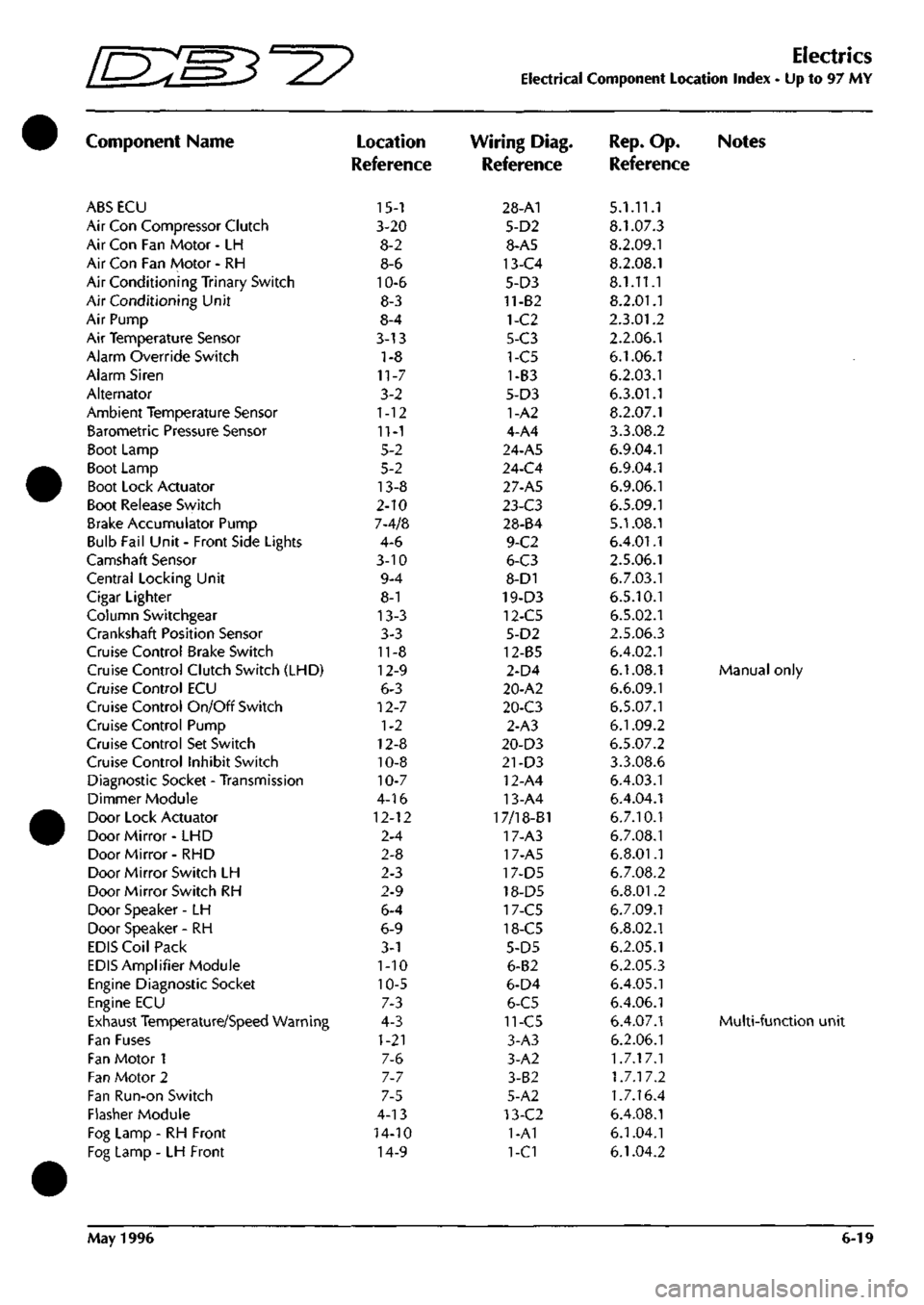
Electrics
Electrical Component Location Index - Up to 97 MY
Component Name
ABS ECU
Air Con Compressor Clutch
Air Con Fan Motor - LH
Air Con Fan Motor - RH
Air Conditioning Trinary Switch
Air Conditioning Unit
Air Pump
Air Temperature Sensor
Alarm Override Switch
Alarm Siren
Alternator
Ambient Temperature Sensor
Barometric Pressure Sensor
Boot Lamp
Boot Lamp
Boot Lock Actuator
Boot Release Switch
Brake Accumulator Pump
Bulb Fail Unit - Front Side Lights
Camshaft Sensor
Central Locking Unit
Cigar Lighter
Column Switchgear
Crankshaft Position Sensor
Cruise Control Brake Switch
Cruise Control Clutch Switch (LHD)
Cruise Control ECU
Cruise Control On/Off Switch
Cruise Control Pump
Cruise Control Set Switch
Cruise Control Inhibit Switch
Diagnostic Socket - Transmission
Dimmer Module
Door Lock Actuator
Door Mirror- LHD
Door Mirror- RHD
Door Mirror Switch LH
Door Mirror Switch RH
Door Speaker -LH
Door Speaker - RH
EDIS Coil Pack
EDIS Amplifier Module
Engine Diagnostic Socket
Engine ECU
Exhaust Temperature/Speed Warning
Fan Fuses
Fan Motor 1
Fan Motor 2
Fan Run-on Switch
Flasher Module
Fog Lamp - RH Front
Fog Lamp - LH Front
Location
Reference
15-1
3-20
8-2
8-6
10-6
8-3
8-4
3-13
1-8
11-7
3-2
1-12
11-1
5-2
5-2
13-8
2-10
7-4/8
4-6
3-10
9-4
8-1
13-3
3-3
11-8
12-9
6-3
12-7
1-2
12-8
10-8
10-7
4-16
12-12
2-4
2-8
2-3
2-9
6-4
6-9
3-1
1-10
10-5
7-3
4-3
1-21
7-6
7-7
7-5
4-13
14-10
14-9
Wiring Diag.
Reference
28-A1
5-D2
8-A5
13-C4
5-D3
11-82
1-C2
5-C3
1-C5
1-B3
5-D3
1-A2
4-A4
24-A5
24-C4
27-A5
l-i-C3
28-84
9-C2
6-C3
8-D1
19-D3
12-C5
5-D2
12-85
2-D4
20-A2
20-C3
2-A3
20-D3
21-D3
12-A4
13-A4
17/18-B1
17-A3
17-A5
17-D5
18-D5
17-C5
18-C5
5-D5
6-B2
6-D4
6-C5
11-C5
3-A3
3-A2
3-B2
5-A2
13-C2
1-A1
1-C1
Rep.
Op. Notes
Reference
5.1.11.1
8.1.07.3
8.2.09.1
8.2.08.1
8.1.11.1
8.2.01.1
2.3.01.2
2.2.06.1
6.1.06.1
6.2.03.1
6.3.01.1
8.2.07.1
3.3.08.2
6.9.04.1
6.9.04.1
6.9.06.1
6.5.09.1
5.1.08.1
6.4.01.1
2.5.06.1
6.7.03.1
6.5.10.1
6.5.02.1
2.5.06.3
6.4.02.1
6.1.08.1 Manual only
6.6.09.1
6.5.07.1
6.1.09.2
6.5.07.2
3.3.08.6
6.4.03.1
6.4.04.1
6.7.10.1
6.7.08.1
6.8.01.1
6.7.08.2
6.8.01.2
6.7.09.1
6.8.02.1
6.2.05.1
6.2.05.3
6.4.05.1
6.4.06.1
6.4.07.1 Multi-functio
6.2.06.1
1.7.17.1
1.7.17.2
1.7.16.4
6.4.08.1
6.1.04.1
6.1.04.2
May 1996 6-19
Page 28 of 421
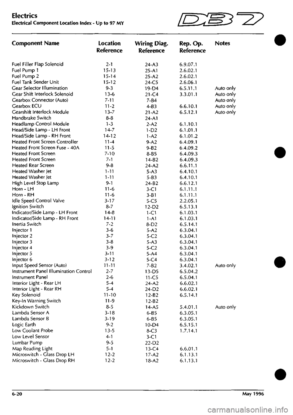
Electrics
Electrical Component Location Index •
Component Name
Fuel Filler Flap Solenoid
Fuel Pump 1
Fuel Pump 2
Fuel Tank Sender Unit
Gear Selector Illumination
Gear Shift Interlock Solenoid
Gearbox Connector (Auto)
Gearbox ECU
Gearshift Interlock Module
Handbrake Switch
Headlamp Control Module
Head/Side Lamp - LH Front
Head/Side Lamp - RH Front
Heated Front Screen Controller
Heated Front Screen Fuse - 40A
Heated Front Screen
Heated Front Screen
Heated Rear Screen
Heated Washer Jet
Heated Washer Jet
High Level Stop Lamp
Horn - LH
Horn - RH
Idle Speed Control Valve
Ignition Switch
Indicator/Side Lamp - LH Front
Indicator/Side Lamp - RH Front
Inertia Switch
Injector 1
Injector 2
Injector 3
Injector 4
Injector 5
Injector 6
Input Speed Sensor (Auto)
Instrument Panel Illumination Control
Instrument Panel
Interior Light - Rear LH
Interior Light - Rear RH
Key Solenoid
Key-In Warning Switch
Kickdown Switch
Lambda Sensor A
Lambda Sensor B
Logic Earth
Low Coolant Probe
Low Level Sensor
Lumbar Pump
Map Reading Light
Microswitch - Glass Drop LH
Microswitch - Glass Drop RH
Up to 97 MY
Location
Reference
2-1
15-13
15-14
15-12
9-3
13-6
7-11
11-2
13-7
8-8
1-3
14-7
14-12
11-4
11-5
7-10
7-1
9-8
1-11
1-11
9-1
11-6
11-6
3-17
8-7
14-8
14-11
7-2
3-6
3-7
3-8
3-9
3-n
3-12
11-11
2-7
2-6
5-4
5-4
11-10
11-9
8-5
3-18
3-19
9-2
13-5
4-1
9-5
5-1
12-2
12-2
Wiring Diag.
Reference
24-A3
25-A1
25-A2
24-C5
19-D4
21-C4
7-B4
4-B3
21-A2
24-A1
2-A2
1-D2
1-A2
9-A2
9-B2
8-B5
14-B2
24-A2
5-A3
5-B3
24-B2
3-C1
3-81
5-C5
12-D2
1-C1
1-A1
8-D2
5-A2
5-C2
5-A3
5-C2
5-A4
5-C4
7-B2
13-D5
11-C5
24-A2
24-D2
12-B2
12-B2
14-A5
6-B5
6-B5
10-D4
8-C3
3-C1
22-D2
13-C4
17-A2
18-A2
Ini^'
IL-^^'^
Rep.
Op.
Reference
6.9.07.1
2.6.02.1
2.6.02.1
2.6.06.1
6.5.11.1
3.3.01.1
6.6.10.1
6.5.12.1
6.1.10.1
6.1.01.1
6.1.01.2
6.4.09.1
6.4.09.2
6.4.09.3
6.4.09.3
6.6.11.1
6.4.10.1
6.4.10.1
6.6.12.1
6.1.11.1
6.1.11.1
2.2.05.1
6.5.13.1
6.1.03.1
6.1.03.1
6.5.14.1
6.3.04.1
6.3.04.1
6.3.04.1
6.3.04.1
6.3.04.1
6.3.04.1
3.4.02.1
6.5.04.2
6.5.04.1
6.6.02.1
6.6.02.1
6.5.14.1
5.4.01.1
6.3.05.1
6.3.05.1
6.5.15.1
1.7.14.1
6.6.01.1
6.1.13.1
6.1.13.1
W3^y
Notes
Auto only
Auto only
Auto only
Auto only
Auto only
Auto only
Auto only
6-20 May 1996
Page 97 of 421
I NO COLOUR AlttA 1503 BW CI
H/BRAKE.
ISWITCH I
HO COLOUR 5 YS 175 PY 259 OR 260 0 261 NR 4T4 YO 475 B 476 BR 479 s 481 B 482 BR 483 LCK 484 RIN 486 RN 487 GR 489 UIN 491 W 492 rw
493
KB
494
BR
495
OR
495
OU
497
SLG
500
KB
501
GB
503
BW
504
GW
505
LGO
506
OW
507
GP
509
OG
829
NO
833
PS
834
NS
835
NY
836
U
841
P
842
PK
850
P
851
PK
855
HP
858
RU
872
BRO
973
HP
975
RU
89J
R
894
WS
896
R
897
WS
902
G
904
0
907
WK
930
WK
AREA
B6 B6 86 86 B6 02 B2 B2 86 C2 C2 B6 A4 Dl
B2-I8I
A4 B6 B6 B6 86 Be 66 B6 B6 B6 Al
C2-I87
C5 A3 B6 A3 B6 B6 B6 C6
C2-185
A3 A3 Dl Dl C4 D4 A4 A5 85 BG B6 86 Be B6 B6 B6 86
HO COLOUR
839 B 840 B
TBtr
B4-I8;
NO COLOUR PIN ARE!" 508 OG I CI 506 OW J a FUEL FILLER FLAP
N6
tbim AREA
873
HP CI
874
BR
C3-I9I
INTERIOR LIGHT
NO COLOUR
PIH
841
P I
842
PK 2
CI
ja
JHEATEC
|BACKLI
J
HEATED
I
BACKLIGHT
I
NO
COLOUR AREA
I
ll>13
B
Ag-I8?l
NO COLOUR
PIN
872
BRD 1
484
RIN 2
W
UIN J
AREA
CI 81 Bl
,
BOOT LAMP,
r^
NO COLOUR
PIN
I
844 B 2
845
CP 3
TBET
A2-I82 C6
LH REAR LAMP
NO COLOUR
PIN
875
RU
876
GN
877
GR
878
B
879
RS
880
GP
1 2 3 4 5 _6
AREA
a
C3-I9C B2-I8I B4-I8; B4-I8<
BG LH
SIDEMARKER
^
HO COLOUR
PIN
JRET
476
BR I Bl
47?
6 i B!
HO COLOUR
PIH
870
RS I
671
B 2_
AREA B4-I8'
SUM
NO
C6L6UD
i^iti
SEET
846 NS I Ce
847
NY 2 C6 848 \l i
C2-I85
(^
482
BR I W i 2_
TSfT
-0 H—— S NO COLOUR 849 TIN AREA JS_J
NO COLOUR AREA 854
BR
C3-I9I 855
HP CI
I BOOT LAMP,
SPL
189
SPL
192
NO COLOUR 865
BR
866
PG
867
RS
868
RG m B
PIN 1 2 3 4 5 6 7
9
.
ARtA C3-I9I 06
ce
03-189 C5-ieB
NO
t6L6ul)
5 YS 175 PY 259 OR 260 0 261 NR 483 LGK 479 S 491 W 492 YW 493 KB 494 8R 495 OR 496 OU 497 SLG 500 KB 901 GB 507 GP 629 NO 833 PS 834 NS 835 NY 845 GP 846 NS 847 NY 849 TIN 852 P 863 GP 866 PG 867 RS
-mr Bl Bl Bl Bl Bl Bl Bl ei Bl Bl Bl Bl Bl Bl CI CI CI CI CI a CI 82 B2 C2 C2 02 04 C5 C5
•w 880 «B5 889 890 891 893 894 896 897 900 902 904 907 918 927 930 932 933 936 939 941
-mem
GP B BR 8 B R WS R WS GH 6 G WK R6 BRD WK GW GR U B RS
-ARIT
86
C5-I92 C3-I9I C5-I92 D2-I68
CI a CI 01
C3-I9C
01 Dl Dl
c3-ies
C2-I86 Dl 0-187 B2-I8I C2-I65 C5-192 C4-I84
RH REAR
LAI*
(5
Dl 05 0 Q B 0
SHEET
27
AREA
C5
.» ^
NO COLOUR AREA 505
LGO CI
'_S C5H92
J
FUEL
I
SENDi
-t
1
FUEL TANK
'
SENDER UNIT
NO COLOUR
PIN
858
RU
859
CN
860
GW
861
8
862
RG
Ki
?F
1 2 3 4 5
.._6_
AREA
CI
C5-I9C C2-I87 02-188 D5-I89
«
INTERIOR! 'LIGHT
I
•HEATED BACKLIGHT'
I
NO
COLOUR i486
RN
AREA 81 HO COLOUR
PIN
AREA
850 P I CI
851
PK 2 CI
NO COLOUR
PIN
I
852
P
474
YG
^ii_
C6 Bl
lK^^2
RH SIDEMARKER NO COLOUR
PIN
AREA 856
RG I
D3-IS9 657
B 2 E2:
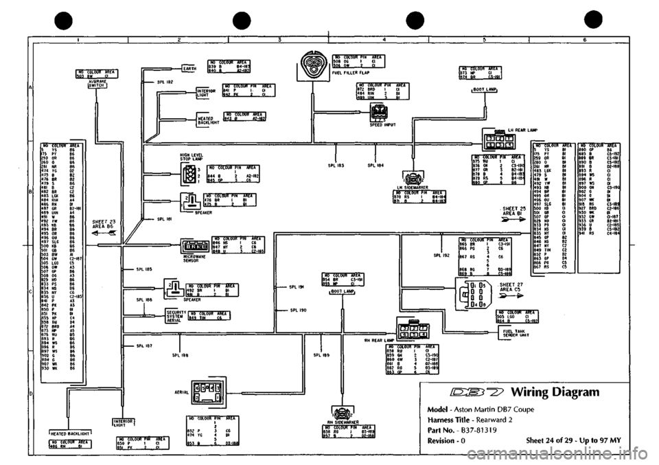
Wiring Diagram
Model - Aston Martin DB7 Coupe
Harness Title - Rearward 2
PartNo.-B37-81319
Revision - 0 Sheet 24 of 29 - Up to 97 MY
Page 108 of 421
^7
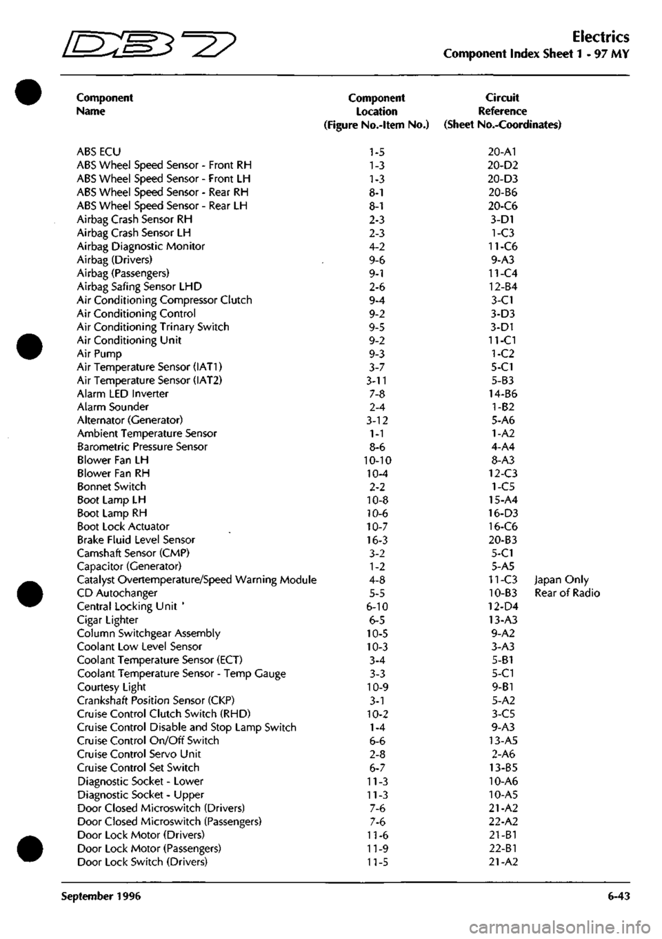
Electrics
Component Index Sheet 1-97 MY
Component
Name
ABS ECU
ABS Wheel Speed Sensor - Front RH
ABS Wheel Speed Sensor - Front LH
ABS Wheel Speed Sensor - Rear RH
ABS Wheel Speed Sensor - Rear LH
Airbag Crash Sensor RH
Airbag Crash Sensor LH
Airbag Diagnostic Monitor
Airbag (Drivers)
Airbag (Passengers)
Airbag Safing Sensor LHD
Air Conditioning Compressor Clutch
Air Conditioning Control
Air Conditioning Trinary Switch
Air Conditioning Unit
Air Pump
Air Temperature Sensor (IAT1)
Air Temperature Sensor (IAT2)
Alarm LED Inverter
Alarm Sounder
Alternator (Generator)
Ambient Temperature Sensor
Barometric Pressure Sensor
Blower Fan LH
Blower Fan RH
Bonnet Switch
Boot Lamp LH
Boot Lamp RH
Boot Lock Actuator
Brake Fluid Level Sensor
Camshaft Sensor (CMP)
Capacitor (Generator)
Catalyst Overtemperature/Speed Warning Module
CD Autochanger
Central Locking Unit '
Cigar Lighter
Column Switchgear Assembly
Coolant Low Level Sensor
Coolant Temperature Sensor (ECT)
Coolant Temperature Sensor - Temp Gauge
Courtesy Light
Crankshaft Position Sensor (CKP)
Cruise Control Clutch Switch (RHD)
Cruise Control Disable and Stop Lamp Switch
Cruise Control On/Off Switch
Cruise Control Servo Unit
Cruise Control Set Switch
Diagnostic Socket - Lower
Diagnostic Socket - Upper
Door Closed Microswitch (Drivers)
Door Closed Microswitch (Passengers)
Door Lock Motor (Drivers)
Door Lock Motor (Passengers)
Door Lock Switch (Drivers)
Component
Location
(Figure No.-ltem No.)
1-5
1-3
1-3
8-1
8-1
2-3
2-3
4-2
9-6
9-1
2-6
9-4
9-2
9-5
9-2
9-3
3-7
3-11
7-8
2-4
3-12
1-1
8-6
10-10
10-4
2-2
10-8
10-6
10-7
16-3
3-2
1-2
4-8
5-5
6-10
6-5
10-5
10-3
3-4
3-3
10-9
3-1
10-2
1-4
6-6
2-8
6-7
11-3
11-3
7-6
7-6
11-6
11-9
11-5
Circuit
Reference
(Sheet No.-Coordinates)
20-A1
20-D2
20-D3
20-B6
20-C6
3-D1
1-C3
11-C6
9-A3
11-C4
12-B4
3-C1
3-D3
3-D1
11-CI
1-C2
5-C1
5-B3
14-B6
1-B2
5-A6
1-A2
4-A4
8-A3
12-C3
1-C5
15-A4
16-D3
16-C6
20-B3
5-C1
5-A5
11-C3 Japan Only
10-B3 Rear of Radio
12-D4
13-A3
9-A2
3-A3
5-B1
5-C1
9-B1
5-A2
3-C5
9-A3
13-A5
2-A6
13-B5
10-A6
10-A5
21-A2
22-A2
21-B1
22-Bl
21-A2
September 1996 6-43
Page 109 of 421
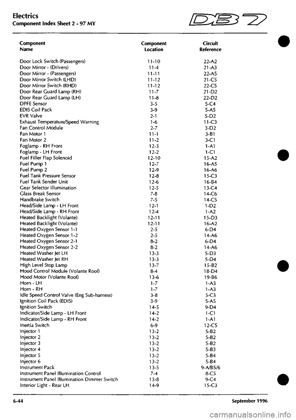
Electrics
Component Index Sheet 2 - 97 MY
Component
Name
Door Lock Switch (Passengers)
Door Mirror - (Drivers)
Door Mirror - (Passengers)
Door Mirror Switch (LHD)
Door Mirror Switch (RHD)
Door Rear Guard Lamp (RH)
Door Rear Guard Lamp (LH)
DPFE Sensor
EDIS Coil Pack
EVR Valve
Exhaust Temperature/Speed Warning
Fan Control Module
Fan Motor 1
Fan Motor 2
Foglamp - RH Front
Foglamp - LH Front
Fuel Filler Flap Solenoid
Fuel Pump 1
Fuel Pump 2
Fuel Tank Pressure Sensor
Fuel Tank Sender Unit
Gear Selector Illumination
Glass Break Sensor
Handbrake Switch
Head/Side Lamp - LH Front
Head/Side Lamp - RH Front
Heated Backlight (Volante)
Heated Backlight (Voiante)
Heated Oxygen Sensor
1
-1
Heated Oxygen Sensor
1
-2
Heated Oxygen Sensor 2-1
Heated Oxygen Sensor 2-2
Heated Washer Jet LH
Heated Washer Jet RH
High Level Stop Lamp
Hood Control Module (Volante Roof)
Hood Motor (Volante Roof)
Horn - LH
Horn - RH
Idle Speed Control Valve (Eng Sub-harness)
Ignition Coil Pack (EDIS)
Ignition Switch
Indicator/Side Lamp - LH Front
Indicator/Side Lamp - RH Front
Inertia Switch
Injector 1
Injector 2
Injector 3
Injector 4
Injector 5
Injector 6
Instrument Pack
Instrument Panel Illumination Control
Instrument Panel Illumination Dimmer Switch
Interior Light - Rear LH
6-44
Component
Location
11-10
n-4
11-11
11-12
11-12
11-7
11-8
3-5
3-9
2-1
1-6
2-7
11-1
11-2
12-3
12-2
12-10
12-7
12-9
12-8
12-6
12-5
7-8
7-5
12-1
12-4
12-11
12-11
2-5
2-5
8-2
8-2
13-3
13-3
13-7
8-4
13-6
1-7
1-7
3-8
3-9
14-5
14-2
14-2
6-9
13-2
13-2
13-2
13-2
13-2
13-2
13-5
7-4
13-8
14-9
fEB^-^?
Circuit
Reference
22-A2
21-A3
22-A5
21-C5
22-C5
21-D2
22-D2
5-C4
5-A5
5-D2
11-C3
3-D2
3-B1
3-C1
1-A1
1-C1
15-A2
16-A5
16-A6
15-C3
16-B4
13-C4
14-C6
14-C5
1-D2
1-A2
15-D3
16-A2
6-D4
14-A6
6-D4
14-A6
5-D3
5-D4
15-82
18-D4
19-B6
1-A3
1-A3
5-C3
5-A5
9-D4
1-C1
1-A1
12-C5
5-B2
5-B2
5-B2
5-B3
5-B4
5-B4
9-A/B5/6
8-C5
9-C4
15-C3
September 1996
Page 264 of 421
5^^
Body and Trim
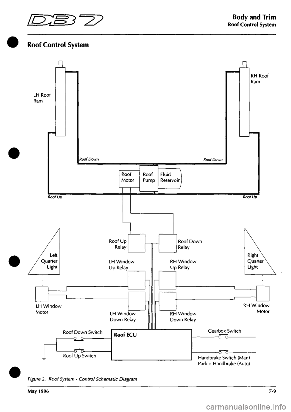
Roof Control System
Roof Control System
LH Roof
Ram
n
Roof Down Roof Down
n
RH Roof
Ram
Roof
Motor
Roof Up
Fluid
Reservoir I
Roof Up
Roof Up
Relay
LH Window
Up Relay
LH Window
Motor LH Window
Down Relay
Roof Down Switch
-o o-
Roof Down
Relay
RH Window
Up Relay
Right
Quarter
Light
RH Window
Down Relay
RH Window
Motor
Gearbox Switch
o~o
o o-Handbrake Switch (Man)
Park + Handbrake (Auto)
Figure 2. Roof System - Control Schematic Diagram
May 1996 7-9
Page 404 of 421
^7
The Aston Martin Lagonda Diagnostic System
Users Guide
Diagnostic Trouble Codes
Introduction
The 'Diagnostic trouble codes' application enables the
PDU to monitor the trouble codes logged in selected
control module's and provides the following functions:
• Decode and display any trouble codes logged by
the control module(s) being monitored.
• Decode and display enhanced diagnostic
information, together with any count of the number
of occurrences, when supported by the control
module(s).
• Clearsomeorallofallthesetroublecodes selected
by the user on the PDU screen, when supported by
the control module(s).
Diagnostic Trouble Codes are logged by the Engine
Management and by the Automatic Transmission control
units and can be accessed using the PDU. Logged codes
in the 95 MY Teves Mk II ABS controller can only be
accessed using the brake warning light. The Air
Conditioning control unit does not log trouble codes.
Operation
From the Main Menu make the following selections:
Select Diagnostics
Select Engine or Transmission
The system will then load the appropriate
software
Select Diagnostic Trouble Codes
Connect the PDU to the car as shown on the
screen diagram
Select the / icon to confirm connection
The PDU will then interrogate the chosen control
unit and will display any logged trouble codes.
If no trouble codes have been flagged by the control
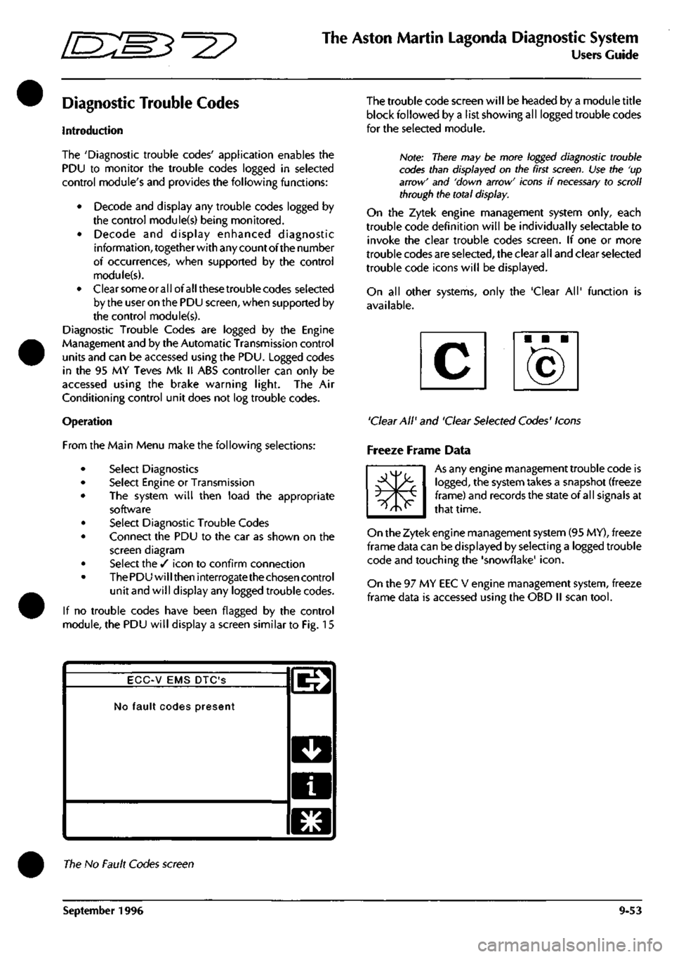
module, the PDU will display a screen similar to Fig. 15
The trouble code screen will be headed by a module title
block followed by a list showing all logged trouble codes
for the seleaed module.
Note: There may be more logged diagnostic trouble
codes than displayed on the first
screen.
Use the 'up
arrow' and 'down arrow' icons if
necessary
to scroll
through the total display.
On the Zytek engine management system only, each
trouble code definition will be individually selectable to
invoke the clear trouble codes screen. If one or more
trouble codes are selected, the clear all and clear selected
trouble code icons will be displayed.
On all other systems, only the 'Clear All' function is
available.
'Clear All' and 'Clear Selected Codes' Icons
Freeze Frame Data
m*
As any engine management trouble code is
logged,
the system takes a snapshot (freeze
frame) and records the state of all signals at
that time.
On the Zytek engine management system (95 MY), freeze
frame data can be displayed by selecting a logged trouble
code and touching the 'snowflake'
icon.
On the 97 MY EEC V engine management system, freeze
frame data is accessed using the OBD II scan
tool.
ECC-V EMS DTC'S
No fault codes present
l^
D
a
El
The No Fault Codes screen
September 1996 9-53
Page 410 of 421
^^?
The Aston Martin Lagonda Diagnostic System
Users Guide
The following trigger options are available:
Triggers when the signal passes above
a
specified
value,
i.e. stop lamp.
Triggers when the signal passes below
a
specified
value,
i.e. Anti-Lock brakes warning lamp.
Triggers when the signa
I
passes outside
a
specified
band,
i.e. oxygen sensor feedback.
Triggers when the signal passes into a specified
band.
Once the type of trigger has been selected the trigger
vaiue(s) (i.e. the signal level at which the trigger point wil
I
occur) should be set.
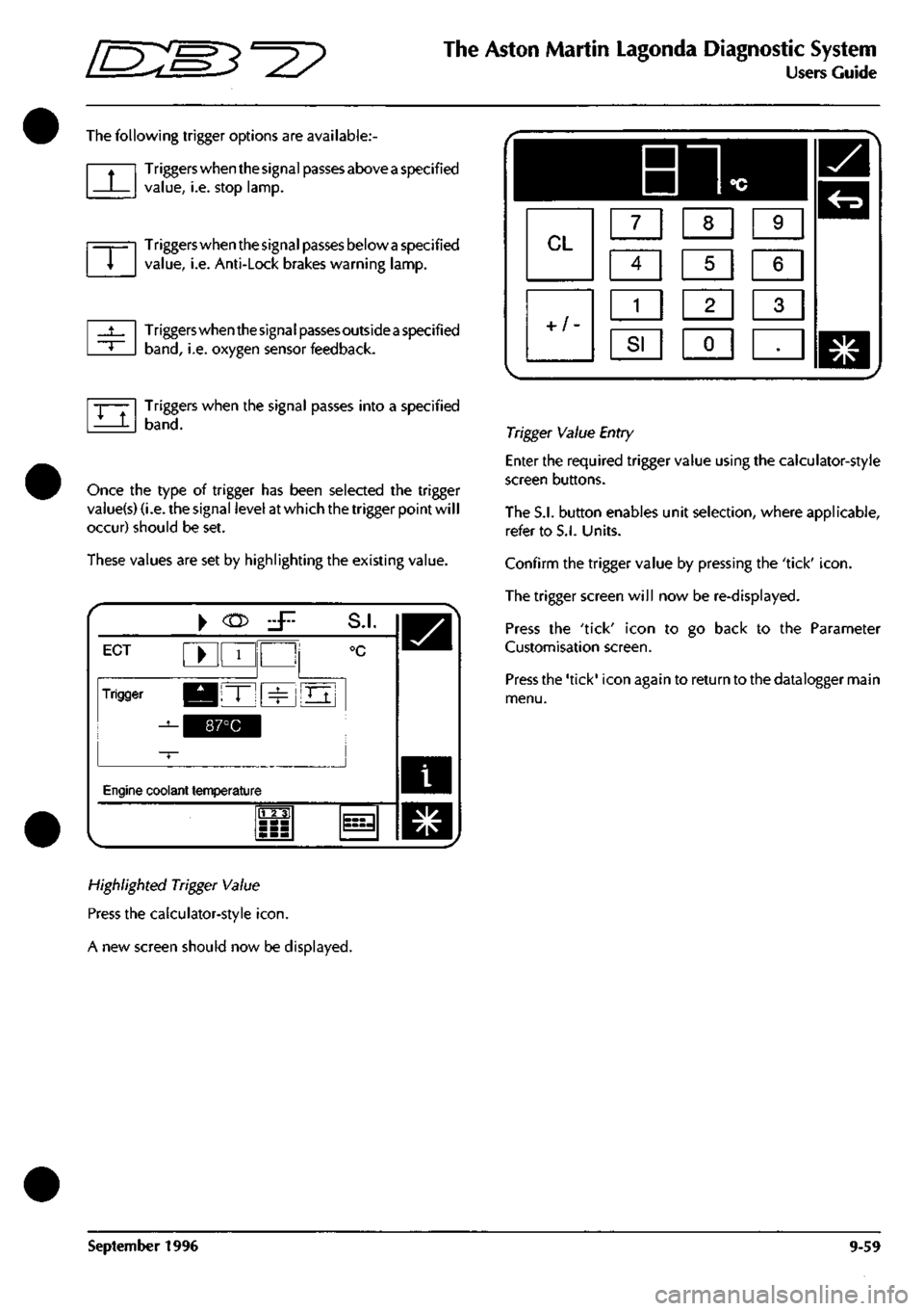
These values are set by highlighting the existing value.
i
ECT ^ 1
Trigger KBIT" ^
^^^^1
S.I.
°c
Oj
Engine coolant temperature
m
^
Highlighted Trigger Value
Press the calculator-style
icon.
A new screen should now be displayed.
Trigger Value Entry
Enter the required trigger value using the calculator-style
screen buttons.
The S.I. button enables unit selection, where applicable,
refer to S.I. Units.
Confirm the trigger value by pressing the 'tick'
icon.
The trigger screen will now be re-displayed.
Press the 'tick' icon to go back to the Parameter
Customisation screen.
Press the 'tick' icon again to return to the datalogger main
menu.
September 1996 9-59
Page 415 of 421
The Aston Martin Lagonda Diagnostic System
Users Guide
ES^"^?
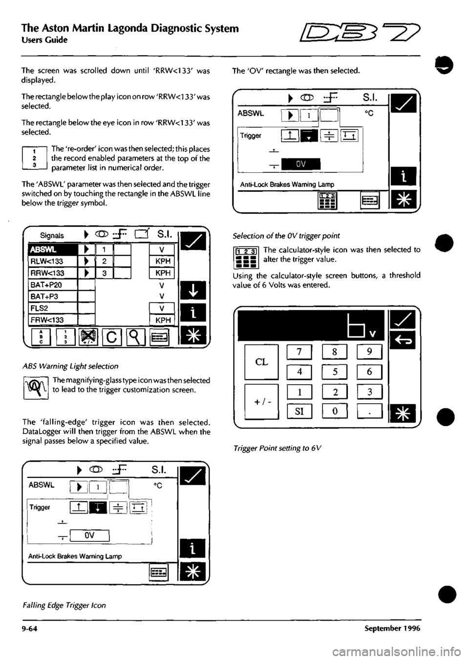
The screen was scrolled down until 'RRW<133' was
displayed.
The rectangle below the play icon on row 'RRW<133' was
selected.
The rectangle below the eye icon in row 'RRW<133' was
selected.
The 're-order' icon was then selected; this places
the record enabled parameters at the top of the
parameter list in numerical order.
The 'ABSWL' parameter was then selected and the trigger
switched on by touching the rectangle in the ABSWL line
below the trigger symbol.
The 'OV rectangle was then selected.
\
(n>
ABSWL
Trigger
S.I.
Anti-Lock Brakes Warning Lamp
1123;
11=3
Signals
ABSWL
RLW<133
RRW<133
BAT+P20
BAT+P3
FLS2
FRW<133
•
KPH
KPH
V
V
^K
KPH
i=
ABS Warning Light selection
^
Themagnifying-glasstype icon wasthen selected
to lead to the trigger customization screen.
The 'falling-edge' trigger icon was then selected.
DataLogger will then trigger from the ABSWL when the
signal passes below a specified value.
Selection of the OV trigger point
The calculator-style icon was then selected to
alter the trigger value. 11 2 31
Using the calculator-style screen buttons, a threshold
value of 6 Volts was entered.
1
7 1 1 8 1 1 9 1
Q
Q
5
1 6 1
LB m
1
^I 1 «J •
Trigger Point setting to 6V
ABSWL
Trigger
Anti-Lock Brak
^
(n>
•
1
'
^H
OV
es Warning L
.jr.
1
S.I.
°C
m
amp
J
l===-l
Falling Edge Trigger Icon
9-64 September 1996