fuel type ASTON MARTIN DB7 1997 Workshop Manual
[x] Cancel search | Manufacturer: ASTON MARTIN, Model Year: 1997, Model line: DB7, Model: ASTON MARTIN DB7 1997Pages: 421, PDF Size: 9.31 MB
Page 21 of 421

3^?
Electrics
Rear Lamp Cluster / Central Locking System / Door Lock Motors
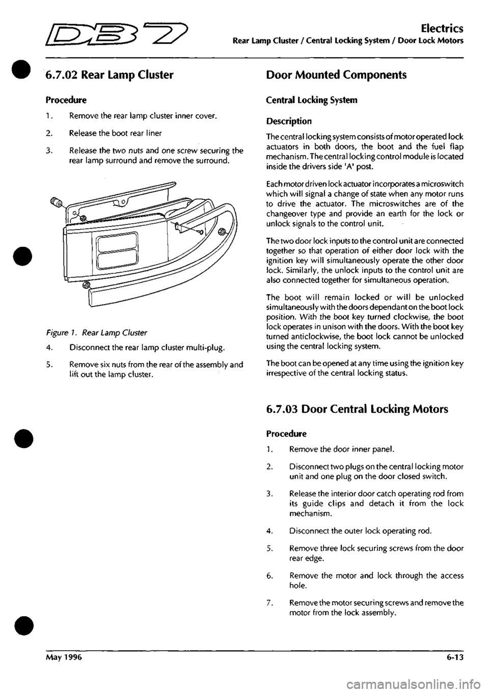
6.7.02 Rear Lamp Cluster Door Mounted Components
Procedure
1.
Remove the rear lamp cluster inner cover.
2.
Release the boot rear liner
3. Release the two nuts and one screw securing the
rear lamp surround and remove the surround.
Figure 7. Rear Lamp Cluster
4.
Disconnect the rear lamp cluster multi-plug.
5. Remove six nuts from the rear of the assembly and
lift out the lamp cluster.
Central Locking System
Description
Thecentral locking system consistsofmotoroperated lock
actuators in both doors, the boot and the fuel flap
mechanism. The central locking control module is located
inside the drivers side 'A' post.
Each motordriven lock actuator incorporatesa microswitch
which will signal a change of state when any motor runs
to drive the actuator. The microswitches are of the
changeover type and provide an earth for the lock or
unlock signals to the control unit.
The two door lock inputs to the control unit are connected
together so that operation of either door lock with the
ignition key will simultaneously operate the other door
lock. Similarly, the unlock inputs to the control unit are
also connected together for simultaneous operation.
The boot will remain locked or will be unlocked
simultaneously with the doors dependant on the boot lock
position.
With the boot key turned clockwise, the boot
lock operates in unison with the doors. With the boot key
turned anticlockwise, the boot lock cannot be unlocked
using the central locking system.
The boot can be opened at any time using the ignition key
irrespective of the central locking status.
6.7.03 Door Central Locking Motors
Procedure
1.
Remove the door inner panel.
2.
Disconnect two plugs on the central locking motor
unit and one plug on the door closed switch.
3. Release the interior door catch operating rod from
its guide clips and detach it from the lock
mechanism.
4.
Disconnect the outer lock operating rod.
5. Remove three lock securing screws from the door
rear edge.
6. Remove the motor and lock through the access
hole.
7. Remove the motor securing screws and remove the
motor from the lock assembly.
May 1996 6-13
Page 417 of 421

The Aston Martin Lagonda Diagnostic System
Users Guide =2?
Training
The training programme incorporated into the PDU
software is designed to cover the needs of new users and
those who have basic PDU skills but require further
training on the DMM and Datalogger functions.
Select 'Training' from the PDU main menu to bring up the
training menu.
New User Training
The new user training program takes the student through
a structured sequence of activities to learn the meaning
and use of the basic screen icons. The traineemay then
work through programmed exercises to learn the digital
multi-meter and then the datalogger functions.
Existing User Training Menu
in this program the existing user may select training from
the following list:
• User Screen Controls
• Digital Multi-Meter
• Datalogger
OBD II Scan Tool (Not 95 MY)
The OBD II Scan Tool is designed to access the memories
of the engine and transmission control units to monitor
and extract data relative to emissions control.
The following types of data may be accessed:
Current Powertrain Data
Monitor Freeze Frame Data
Request Trouble Codes
Clear Trouble Codes
Request Oxygen Sensor Test Results
Monitor Oxygen Sensors
Display Pending Trouble Codes
Request On-Board Monitoring Test Results
Examine Readiness Tests
Malfunction Lamp Status
The data to be monitored is selected from the OBD
11
main
menu.
For example if Monitor Freeze Frame Data is selected, the
system will display up to 11 parameters which are always
recorded when a fault code is logged. The parameters are
as follows:
0 : SUPP Supported
2 : FCFF Fault Causing Freeze Frame
3 : FSS Fuel System Status
4 : CLV Calculated Load Value
5 : ECT Engine Coolant Temperature
6 : STFT-B1 Short Term Fuel Trim - bank 1 (Cyl
1
-3)
7 : LTFT-B1 Long Term Fuel Trim - bank
1
(Cyl 1-3)
8 : STFT-B2 Short Term Fuel Trim - bank 2 (Cyl 4-6)
9 : LTFT-B2 Long Term Fuel Trim - bank 2 (Cyl 4-6)
12:RPM .Engine Speed
13:VS Vehicle Speed
•'••) ••