length ASTON MARTIN DB7 1997 Workshop Manual
[x] Cancel search | Manufacturer: ASTON MARTIN, Model Year: 1997, Model line: DB7, Model: ASTON MARTIN DB7 1997Pages: 421, PDF Size: 9.31 MB
Page 188 of 421
Electrics
Airbag System =7?
Spillage and Leakage
If material is spilled or released, contact Aston
Martin Technical Support for advice on clean-up
procedures. All personnel must be kept away from
the contaminated area.
Do not dispose of contaminated propellant or
water into storm or sanitary sewers, ground water
or
soil.
Spills may be reportable to state and/or federal
authorities.
Materials must be disposed of by incineration or
chemical oxidation under carefully controlled
conditions by specially trained individuals and in
accordancewith local stateandfederal regulations.
Scrapping Vehicles with Live Airbags
when scrapping a vehicle with live airbags, first
deploy the airbags in accordance with the following
procedure. This procedure assumes that the airbag
wiring is undamaged
See Handling/Safety Information.
If the airbags are to be removed, see the airbag
module assembly/removal/servicing instructions.
Equipment required:
Four insulation displacement connectors
(scotch locks).
Charged 'slave' battery.
Two 10 metre lengths of
1
mm^ wire fitted with
crocodile clips on one end.
Procedure
WARNING: The deployment procedure must be
carried out outdoors away from other personnel.
1.
Remove any loose debris from around the airbag
modules and ensure that no flammable liquids are
present.
2.
Disconnect the vehicle battery.
WARNING: Always connect to the airbag
first,
as
the bag will deploy immediately on connection to
the battery.
3. Remove the passenger side airbag deployment
door and underscuttle panel.
4.
Remove the drivers side underscuttle panel.
5. Disconnect the airbag connector for the spiral
cassette under the fascia and at the wire (drivers
side).
6. Locate the harness connectors and cut the wires
leading from the airbag just above the mating plug
(passengers side).
Note: The harness connected between the driver's
airbag
and the connector
has
one red
feed
wire and
one
grey/orange return
wire.
The
harness
connected between
the
passenger's
airbag and the connector
has
one blue/
orange
feed wire and one
pinl
return wire.
6-72 September1996
Page 230 of 421
Body and Trim //-->> ^izz^^ ' ^ ^
Body Repair ' —^^ '-^ >^-/
Body Repair
Introduction
This section contains information for the body repair and rectification of the vehicle. Wherever possible the vehicle
must be returned to its original manufactured condition. Following repair the vehicle must be fully checked and, if
necessary, the braking system and steering must be fully reset.
Health and Safety
Ensure that the correct working practices are established before beginning work.
Observe that the correct working practices are followed whether they be legislative or common sense.
Be aware of the potential risks of using materials used in the manufacture and repair of vehicles and take the
appropriate precautions.
Warning: Make sure that the working practices for the air conditioning
system
are followed: do not vent the refrigerant
directly into the atmosphere and always use the approved recovery/recycle /recharge equipment, always wear
suitable protective garments to prevent injury to the eyes and the skin.
Potential Risks
Paint
If the organic solvents, contained in paints, are inhaled for any length of time damage can be caused to the liver,
kidneys, respiratory tract and the digestive system.
Prolonged exposure to isocyanates can cause lung sensitisation and asthma-like symtoms can develop with
subsequent re-exposure to even low concentrations.
Solvent inhilation can cause dizziness or loss of consciousness.
Inhilation of spray dust and sanding debris can cause lung damage.
Paint activatorsand additives will damage the eyesor can cause dermatitis if allowed to splash and come into contact
with these areas. Peroxide and acid catalysts can cause burns.
Applied heat
There is considerable risk of damage to the eyes and skin when welding or flame cutting.
Fire is a serious danger as many materials and fluids in the vehicle are inflammable.
Toxic and dangerous fumes can be liberated when the following are subjected to heat; expanded foam, corrosion
protection,
adhesive and sealing compounds,
trim,
seat material and paints that contain isocyanates.
When heated to
a
temperature of 300°C, polyu rethane based compounds can
1
iberate small quantities of isocyanate.
Many types of nitrogen containing chemicals may be liberated as breakdown products, these chemicals can
contain isocyanates, oxides of nitrogen and hydrogen cyanide.
Potentially toxic or asphyxiant fumes and gases are produced by welding, for example; zinc oxide with zinc coated
panels and ozone gas from the MIC process.
Metal repair
There is considerable risk of damage to the eyes, ears and skin when metal cutting, forming and dressing is being
carried out.
Soldering may be hazardous because of heat generated fumes and skin contact with the materials.
7-2 May 1996
Page 232 of 421

Body and Trim
Body Repair ^^
Steel Body Parts - Repair^ Remove and
Replace
Removal
1.
Expose the resistance spot
weld.
For those spot
welds that are not obviously visible use a rotary
wire brush fitted to an air drill or a hand held wire
brush.
9.
Prepare the new panel joint edges for welding by
cleaning to bright metal, both interior and exterior
edges.
Apply weld through primer or inter-weld sealer to
all surfaces to be resistance spot welded.
Where appropriate, apply metal-to-metal adhesive
or sealer in accordance with the manufacturer's
instructions.
Caution: Do not
burn
off undersea I,
use a
'hot knife' or
a
suitable solvent.
2. Cut out the spot welds using aZipcutter or roto-Bor.
At this point it may be necessary to cut out the bulk
of a panel using a pneumatic saw.
Note: On
some
panels,
before removing the bulk of the
panel, brazed
areas
and MIC welded
seams
should be
removed.
3. Separate the spot welded joints and remove the
panel remnants.
Preparing Old Surfaces
1.
Remove the weld nuggets with a sander and 36 grit
disc.
2.
Clean all flanges to a bright smooth finish.
3. Straighten existing panel joint edges as required.
Preparing New Surfaces
1.
Mark off the area of the new panel and cut to size
leaving approximately two inches overlap on the
existing panel
2.
Offer up the new panel or section and align it with
the associated parts.
3. Clamp the panel into position.
4.
Where necessary, cut the new and original panels
to form a but joint.
5. Remove all clamps and the new panel.
6. If required, apply the inner panel protection and or
sound insulation.
Panel Alignment
1.
Align the replacement panel with the associated
panel and clamp it in position.
2.
With certain panels it may be necessary to tack
weld or use PK screws.
Welding
1.
MIC tack the butt joints.
2.
Re-check the alignment and the panel contours as
necessary.
3. Select the correct arms for resistance spot welding
and ensure that the tips are correctly trimmed.
Note: It
is
recommended that
the arms are
not more than
12 in (300 mm) in length.
4.
Test the equipment for satisfactory operation using
test coupons.
In the absence of test equ ipment
a
satisfactory weld
can be verified by pulling the test coupons apart
and viewing the welded condition.
5. Resistance spot weld where required. Note the
presence of zinc coated panels and treat as
previously described.
6. Dress back all MIC tack welds.
7. MIG seam weld the butt joints.
8. Dress all welds as required.
9. Final brazeand lead load as necessary priorto paint
preparation.
7-4 May 1996
Page 273 of 421
Body and Trim
Roof Seals - Adjustment
9.2.01.6 - Roof
Seals
- Adjustment
Seal adjustment is done in two stages. First stage -
lateral adjustment, and second stage - outward
adjustment. Seals are packed out using selected
packing strips.
Lateral Adjustment
Partially open the roof.
Front frame seal only: Remove the seal retaining
plate.
Remove the seal from the channel.
Slacken the channel securing screws and reposition
the channel as required, moving it on the slotted
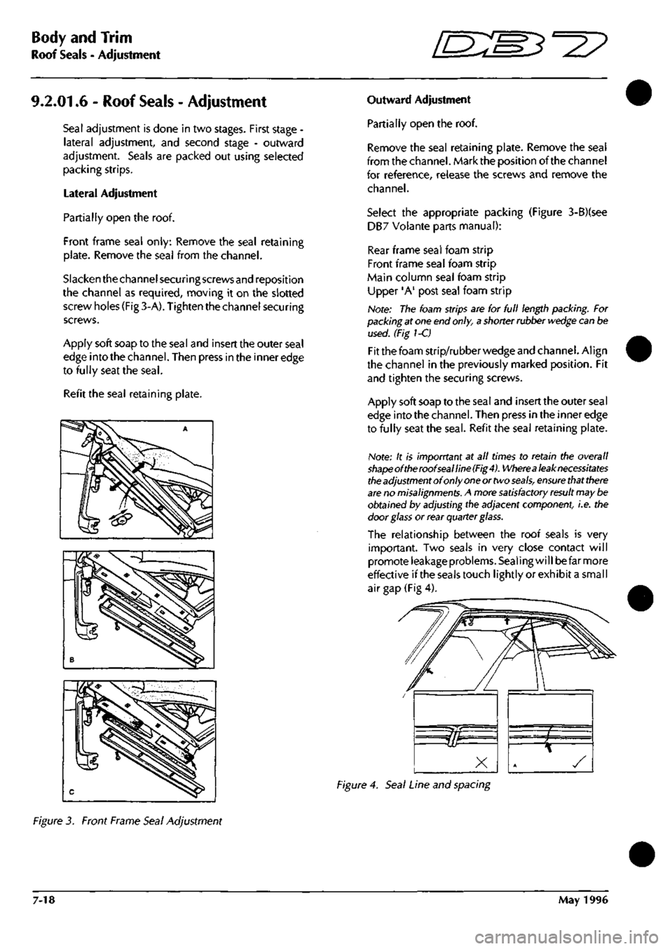
screw holes (Fig 3-A). Tighten the channel securing
screws.
Apply soft soap to the seal and insert the outer seal
edge into the channel. Then press in the inner edge
to fully seat the
seal.
Refit the seal retaining plate.
Outward Adjustment
Partially open the roof.
Remove the seal retaining plate. Remove the seal
from the channel. Mark the position of the channel
for reference, release the screws and remove the
channel.
Select the appropriate packing (Figure 3-B)(see
DB7 Volante parts manual):
Rear frame seal foam strip
Front frame seal foam strip
Main column seal foam strip
Upper 'A' post seal foam strip
Note: The foam strips are for full length packing. For
packing at one end
only,
a shorter rubber
wedge
can be
used. (Fig 1-C)
Fit the foam strip/rubber wedge and channel. Align
the channel in the previously marked position. Fit
and tighten the securing screws.
Apply soft soap to the seal and insert the outer seal
edge into the channel. Then press in the inner edge
to fully seat the
seal.
Refit the seal retaining plate.
Note: It is imporrtant at all times to retain the overall
shapeoftheroofsealline(Fig4).
Wherea
leak necessitates
the
adjustment of only
one
or two
seals,
ensure
that
there
are
no
misalignments.
A more
satisfactory result
may be
obtained by adjusting the adjacent component, i.e. the
door
glass
or rear quarter glass.
The relationship between the roof seals is very
important. Two seals in very close contact will
promote leakage problems. Sealing will be far more
effective ifthe seals touch lightly or exhibit a small
air gap (Fig 4).
Figure 4. Seal Line and spacing
Figure 3. Front Frame Seal Adjustment
7-18 May 1996
Page 293 of 421
Air Conditioning //—^ ^ci^^ • ^ ^
Fnnrtlnn;il fhprk I *-/ -^ r <
Procedure Normal System Reaction
16.
Select ECO Blower flaps revert to fresh air position
17.
Select AC Engine revs change then stabilise
18.
Select fan speed 3 Small increase in fan speed
19.
Select fan speed 2 Fan speed lower
Centre vent and dash end cold
footwell cool
20.
Select MAX temperature
allow in-car temperature to stabilise Hot air from footwell,
(Passenger side underscuttle panel must be in place) warm from dash end
21.
Select MIN temperature and mid face level System goes to full cooling automatically
Cold air from all vent except from screen vent
Centre vent open
Blower at re-circulation
22.
Select DEMIST and full heat Demist vents open, centre vent closes and
blower flaps revert to fresh air position
System check now complete System good.
Note: A small amount of air will bleed from the
ends
of the
demist-defrost vents
in all
cases,
but there should be no leak along
the length of the vents.
8-16 May 1996
Page 411 of 421
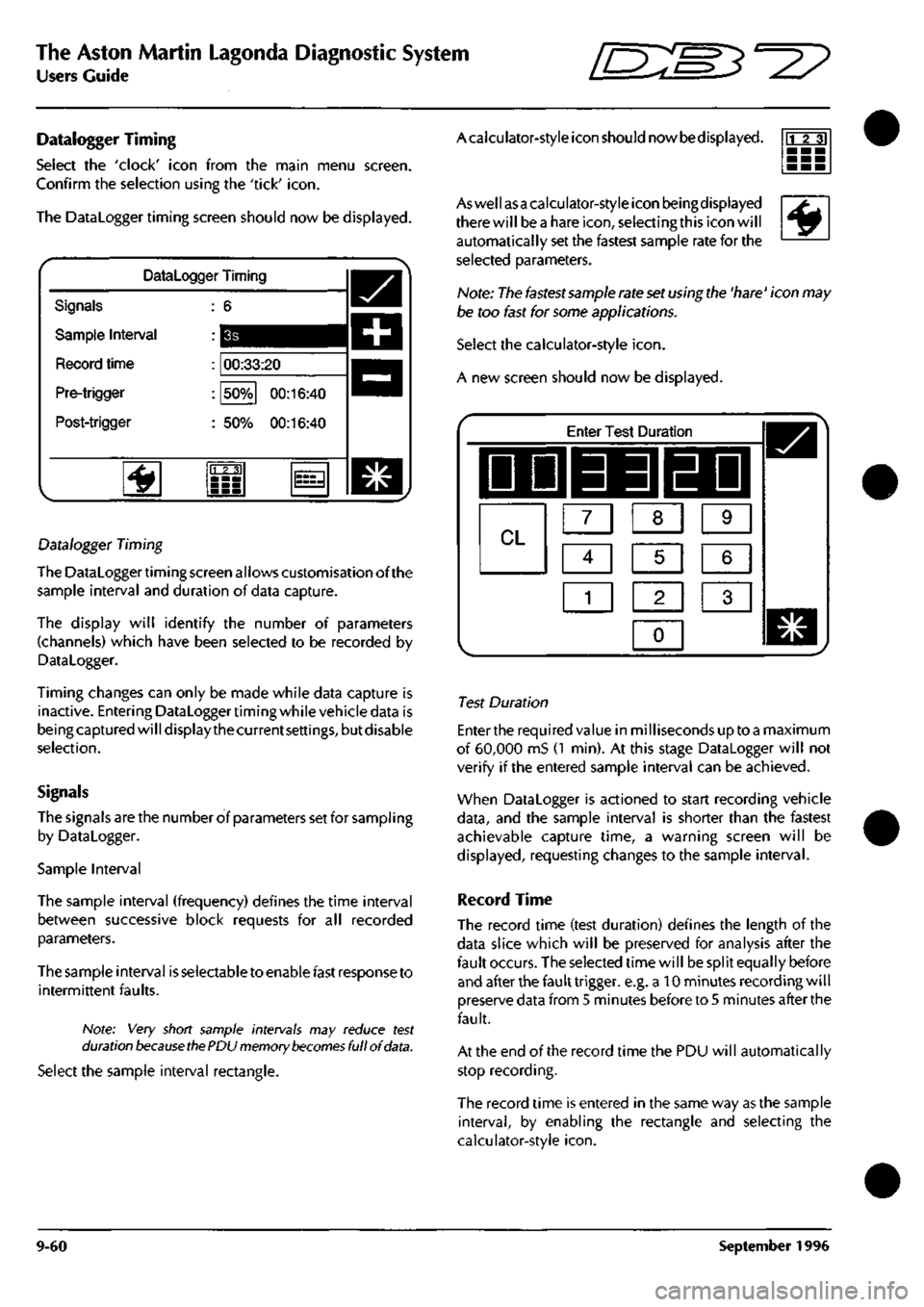
The Aston Martin Lagonda Diagnostic System
Users Guide ^?
Datalogger Timing
Select the 'clock' icon from the main menu screen.
Confirm the selection using the 'tick'
icon.
The Datalogger timing screen should now be displayed.
Datalogger Timing
Signals
Sample Interval
Record time
Pre-trigger
Post-trigger
00:33:20
50%
00:16:40
50%
00:16:40
'^
23]
Datalogger Timing
The Datalogger timing screen allows customisation of the
sample interval and duration of data capture.
The display will identify the number of parameters
(channels) which have been selected to be recorded by
Datalogger.
Timing changes can only be made while data capture is
inactive. Entering Dataloggertiming while vehicle data is
being captured will display the current
settings,
but disable
selection.
Signals
The signals are the number of parameters set for sampIing
by Datalogger.
Sample Interval
The sample interval (frequency) defines the time interval
between successive block requests for all recorded
parameters.
The sample interval is selectable to enable fast response to
intermittent faults.
Note: Very short sample intervals may reduce test
duration
because ttie
PDU memory
becomes
full of
data.
Select the sample interval rectangle.
Acaiculator-style icon should nowbedisplayed. rrr?]
^
Aswellasa calculator-style icon beingdisplayed
there will bea hare
icon,
selecting this icon will
automatically set the fastest sample rate for the
selected parameters.
Note: The fastest sannple rate set using the 'hare' icon may
be too fast for some applications.
Select the calculator-style
icon.
A new screen should now be displayed.
Enter Test Duration
IDD 33 EDI
CL m m [Z]
Ci] ra [I]
1
1 2 1 3 1
0
1
Test Duration
Enter the required value in milliseconds up toa maximum
of 60,000 mS (1 min). At this stage Datalogger will not
verify if the entered sample interval can be achieved.
When Datalogger is actioned to start recording vehicle
data,
and the sample interval is shorter than the fastest
achievable capture time, a warning screen will be
displayed,
requesting changes to the sample interval.
Record Time
The record time (test duration) defines the length of the
data slice which will be preserved for analysis after the
fault occurs. The selected time will be split equally before
and after the fault trigger, e.g. a 10 minutes recording will
preserve data from 5 minutes before to 5 minutes after the
fault.
At the end of the record time the PDU will automatically
stop recording.
The record time is entered in the same way as the sample
interval,
by enabling the rectangle and selecting the
calculator-style
icon.
9-60 September 1996