power steering ASTON MARTIN DB7 1997 Workshop Manual
[x] Cancel search | Manufacturer: ASTON MARTIN, Model Year: 1997, Model line: DB7, Model: ASTON MARTIN DB7 1997Pages: 421, PDF Size: 9.31 MB
Page 14 of 421

Electrics
Starter Motor / Steering Wheel - Removal Procedures ^n:M3^^2?
6.3.02 Starter Motor
Procedure
1.
Disconnect the battery.
2.
Remove the inlet air trunkins
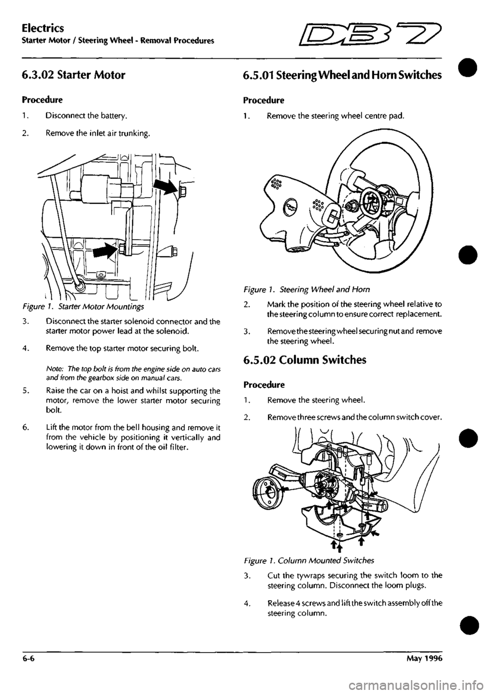
Figure 1. Starter Motor Mountings
3. Disconnect the starter solenoid connector and the
starter motor power lead at the solenoid.
4.
Remove the top starter motor securing bolt.
Note:
The
top bolt is from tlie
engine
side on auto
cars
and from ttie gearbox side on manual cars.
5. Raise the car on a hoist and whilst supporting the
motor, remove the lower starter motor securing
bolt.
6. Lift the motor from the bell housing and remove it
from the vehicle by positioning it vertically and
lowering it down in front of the oil filter.
6.5.01 Steering
Wheel and Horn
Switches
Procedure
1.
Remove the steering wheel centre pad.
Figure 1. Steering Wheel and Horn
2. Mark the position of the steering wheel relative to
the steering column to ensure correct replacement.
3. Removethesteeringwheelsecuringnutand remove
the steering wheel.
6.5.02 Column Switches
Procedure
1.
Remove the steering wheel.
2.
Remove three screws and the column switch cover.
1^
Figure 1. Column Mounted Switches
3. Cut the tywraps securing the switch loom to the
steering column. Disconnect the loom plugs.
4.
Release 4 screws and
1
ift the switch assembly off the
steering column.
6-6 May 1996
Page 187 of 421

^=2?
Electrics
Airbag System
Eye Protection
Chemical protective goggles are recommended
where there is a possibility of eye contact with the
propellant. Safety glasses with side shields are
recommended for all other operations.
Protective Clothing
Approved protective gloves, overalls and shoes/
boots should be worn.
Handling and Storage Precautions
Do not store airbag modules near live electrical
equipment or circuitry. Store in a dry environment
at ambient temperatures.
Good housekeeping and engineering practices
should be employed to prevent the generation and
accumulation of
dusts.
Store in compliance with all
local state and federal regulations.
Driver and Passenger Airbag Modules
Assembly/Removal/Service Instructions
WARNING: In the event of a vehicle impact where the
airbags and the seatbeltpretensioner (if fitted) are
deployed, the following actions MUST be
performed:
Check the condition of the seatbelts, steering
wheel,
steering column, all connections to airbags,
and the column switchgear connectors for integrity
and damage. If in any
doubt,
replace suspected
parts for new parts.
Replace both crash
sensors,
the
safing sensor
and
the seatbelt pretensioner module (if fitted).
On completion of all repair procedures, switch on
the ignition and check that the
Airbag/SRS
warning
light comes on when the ignition is switched on
and extinguishes after approximately six seconds
indicating satisfactory completion of the airbag
and pretensioner
system
self
tests.
WARNING: Before starting
work,
ensure
that the ignition
switch is in position 'O' and the ignition key is
removed.
Disconnect the battery negative lead
within 12 seconds of switching off the ignition to
prevent the alarm system triggering.
As the airbag control module is equipped with a
back-up power source and due to the risk of the
airbag being inadvertently deployed, wait one
minute or longer after disconnecting the battery
before starting work on the airbag module.
• Disconnectingthe battery negative cable cancels
the memory for the 'one-touch' window down
system and stops the vehicle clock. Reset the
window memory and the clock when work is
completed.
• Never use airbags from other vehicles, always
use new parts.
• After work is completed, reconnect the battery
and perform the airbag warning light check
• Never use electrical probes to check voltage or
electrical resistance of the airbag modules.
• Disconnect the airbag before carrying out any
work on, or in the vicinity of the module, or
when using electric welding equipment.
• Always ensure that the battery negative lead has
been disconnected for at least one minute before
commencing any removal procedure.
September 1996 6-71
Page 194 of 421

Electrics
Airbag System '=2?
Airbag System Diagnostics
System Description
The airbag system installation comprises:
Airbag Diagnostic Module
Driver and passenger airbag modules
Two front impact (crash) sensors
One 'safing' sensor
Dedicated wiring harness
SRS indicator/warning lamp
The system is designed to provide protection for
both driver and front seat passenger by automatical ly
deploying airbags in the event of
a
collision during
forward travel.
In the event of a collision, the crash and safing
sensors will operate, completing the firing circuit
and causing the airbags to inflate within 32
milliseconds. At least one crash sensor and the
safing sensor must operate to fire the airbags.
Any faults in system components, installation or
wiring will be indicated by a flashing code on the
SRS/AIRBAG warning lamp. Fault code information
may also be monitored using the PDU or scan
tool.
Component Descriptions
Airbag Diagnostic Module
The airbag diagnostic module is mounted on top of
the passenger airbag mountingcage.Thediagnostic
module contains the microprocessor which is
connected to the complete airbag system. The state
of the three system sensors, the two airbag modules
and the wiring harness is constantly monitored by
the microprocessor for faults and for sensor
activation (crash) conditions.
The diagnostic module also confirms correct supply
voltage by comparing
a
direct battery voltage input
with a similar input via the ignition switch.
The diagnostic module contains a reserve power
supply, enabling the airbags to fire even if the
supply voltage is lost due to collision damage. The
reserve power charge will be retained for
approximately one minute if the positive battery
supply is lost in a collision. An auxiliary internal
circuit known as the 'dwell enhancer' provides a
temporary ground if normal system ground was lost
in a collision.
Wiring Harness
A dedicated electrical wiring harness is used to
connect all system components to the bulkhead
harness. To allow free movement of the steering
mechanism, a cable reel cassette is used to connect
the drivers airbag in the steering wheel to the airbag
harness on the steering column.
Airbag Modules
The two airbag modules contain achargeof sodium
azide/copper oxide which wi
11
generate
a
sufficient
volume of nitrogen gas to fully inflate the airbag
when ignited by an electrical impulse. The volume
of gas is greater in the passenger side airbag due to
its larger size.
Both airbag modules, including the surrounding
trim of the drivers airbag, are non-serviceable and
once deployed, must be renewed as a complete
assembly.
Crash and Safing Sensors
The two crash sensors are mounted one at either
side of the bumper mounting cross member, outside
of the bonnet hinges.
The safing sensor is mounted in the base of the
drivers side 'A' post.
The two crash sensors and the safing sensor
determine when airbag deployment is necessary in
a crash condition.
The sensor contacts will only close when the vehicle
suffers a forward impact of sufficient force. At least
one crash sensor and the safing sensor contacts
must close before the airbags will deploy. The
doubletrigger strategy
is
used to prevent deployment
during trivial impacts such as contacts during
parking.
6-78 September 1996
Page 196 of 421

Electrics
Airbag System ^2?
6.4.21.4
Airbag Disarming/Arming
Procedures
WARNINGS AND CAUTIONS:
WARNINGS:
Disarm the airbags by disconnecting the battery
ground (black)
lead,
waiting one minute and then
removing the airbag modules before servicing of
any airbag or steering column component.
After disconnecting the battery ground
lead,
allow
a minimum of one minute delay for the back-up
power supply to discharge before servicing the
airbag system.
The system components are non-serviceable, if
faults are
suspected,
change components for new
items
only.
Failure to observe the above procedures may
result in accidental deployment of the airbags.
Always wear safety
glasses
when working on airbag
equipped vehicles.
Personnel carrying an airbag module must ensure
that the module and trim cover are pointing away
from the
body.
When positioning on a bench or
work surface, ensure that the airbag module and
trim cover face upwards to limit motion on
accidental deployment.
Always wear
gloves
when handling deployed airbag
modules. Deposits of sodium hydroxide may be
presenton the module surface. If sodium hydroxide
contacts any area of the skin, wash the affected
area immediately with mild soap and
water.
Dispose of the deployed airbag using the correct
procedures referred to in this section.
Cautions:
When scrapping vehicles,
ensure
that the
airbags
have
been deployed (see
Scrapping Vehicles
with Live
Airbags).
If a component
has been
renewed and the fault
does
not
clear,
refit the original item and repeat the diagnostic
procedure.
After
servicing,
repeatthe diagnostic
procedures
to ensure
correct
system
operation.
Renew
the airbag module if the surrounding trim
panels
are
damaged.
Do not attempt to repaint trim covers as
paint may
damage
cover material.
Disarming the Airbags
3.
4.
WARNING: Carry out the following disarming
procedure before attempting any work on the
vehicles electrical
systems.
Note: The battery ground (black) lead must be
disconnected within 12 seconds of switching off the
ignition to avoid the alarm siren sounding.
Disconnect the battery ground
lead.
Allow a
minimum of one minute delay for the back-up
power supply to discharge.
Remove the drivers side airbag module and replace
it with an airbag simulatorfrom the simulator kit (Pt
No.
43.27028).
Remove the passengers airbag module and replace
it with an airbag simulator from the simulator kit.
Reconnect the battery ground.
Rearming the Airbags
WARNING: Carry out the following procedure to
rearm and check the airbags after completing all
work on the vehicles electrical
systems.
Note: The vehicle battery
must be
disconnected within
12
seconds
of switching off
the
ignition
to
avoid the alarm
siren sounding.
^. Disconnect the battery ground
lead.
Allow a
minimum of one minute delay for the back-up
power supply to discharge.
2.
Removethedriverssideairbagsimulatorand replace
it with the drivers airbag module. Secure the airbag
module with the two captive torx screws.
3. Remove the passengers side airbag simulator and
replace it with the passenger side airbag module.
Secure the module with four nuts and washers.
Close the passenger side airbag door.
4.
Reconnect the battery ground.
5. Switch on the ignition and check for correct
indications from the SRS/AIRBAG warning light.
TheSRS/AIRBAC lamp should come on after
a
brief
delay and remain on for approximately six seconds
during the airbag system self check. The lamp will
extinguish upon satisfactory completion of the self
check, or will flash a diagnostic code if an airbag
system fault is detected. Continuous illumination of
the warning lamp may indicate a seatbelt
pretensioner fault
Note:
Reset the
clock and window
ECUs
on completion.
6-80 September 1996