seat memory ASTON MARTIN DB7 1997 Workshop Manual
[x] Cancel search | Manufacturer: ASTON MARTIN, Model Year: 1997, Model line: DB7, Model: ASTON MARTIN DB7 1997Pages: 421, PDF Size: 9.31 MB
Page 93 of 421

N6
WLdUlt PIN 823 8 I 824
R
2 826
R8
3 825
RO
1
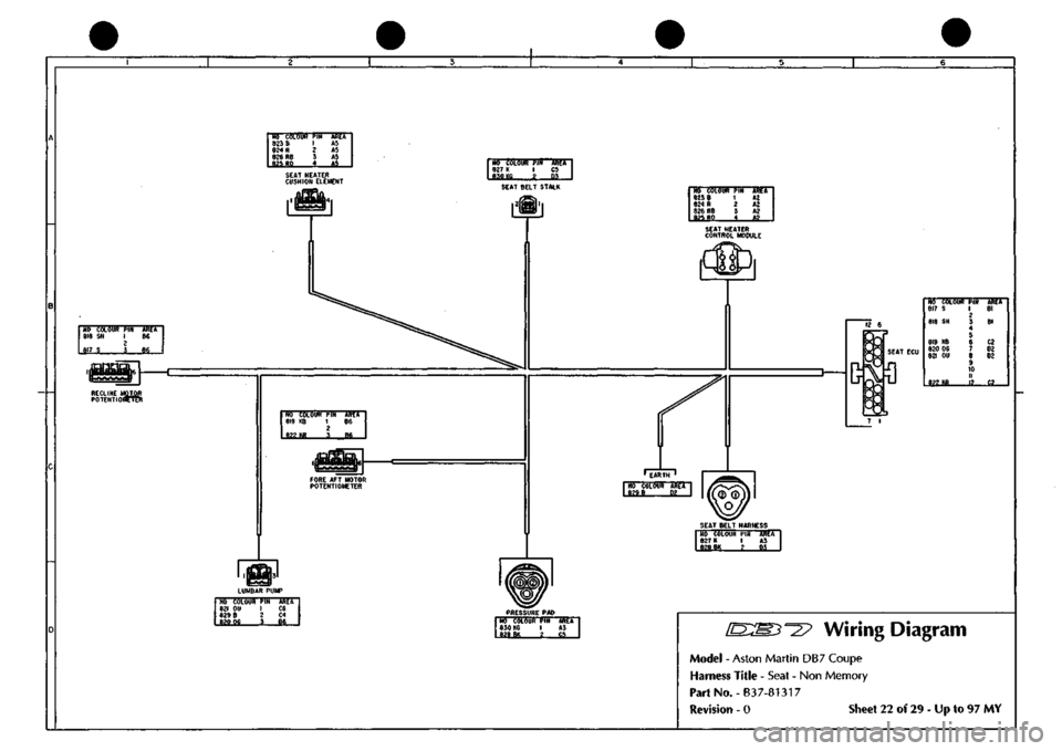
Mi AS AJ AJ A5 SEAT HEATER CUSHION ELEMENT
NO COLOUR PIN 827
K
I 630 KG g
MET CS
SEAT BELT STALK NO COLOUR I^IN 823 8 1 824
R
2 826
R8
3 a?f,
RO
4
HdU A2 A2 A2
AJ
„
SEAT HEATER CONTROL MODULE
NO COLOUR
PIN
AREA 818
SN 1 B6
2 817
S 3 86
>iinBBU|6
RECLINE MOTOR POTENTIOBPTn!
NO COLOUI 817
S
818
SN
819
KB
820
06
821
OU
m
m
TUT 1 2
5 6 7
• li 12
-KKtr Bl
Bl
02 D2 02
C2
SEAT BELT HARNESS NO COLOUR
PIN 827 K 1 828
BK
2
ASA A3
ti
NO COLOUR
PIN
ARET
821
OU I C6
829
8 2 C4
620 06
I SSi.
PRESSURE
PAD
NO COLOUR
PIN
830 K6
I £iiM 2
AREA A3 i5_
[D:My^^2?
Wiring Diagram
Model - Aston Martin DB7 Coupe
Harness Title - Seat - Non Memory
PartNo.-B37-81317
Revision - 0 Sheet 22 of 29 - Up to 97 MY
Page 187 of 421

^=2?
Electrics
Airbag System
Eye Protection
Chemical protective goggles are recommended
where there is a possibility of eye contact with the
propellant. Safety glasses with side shields are
recommended for all other operations.
Protective Clothing
Approved protective gloves, overalls and shoes/
boots should be worn.
Handling and Storage Precautions
Do not store airbag modules near live electrical
equipment or circuitry. Store in a dry environment
at ambient temperatures.
Good housekeeping and engineering practices
should be employed to prevent the generation and
accumulation of
dusts.
Store in compliance with all
local state and federal regulations.
Driver and Passenger Airbag Modules
Assembly/Removal/Service Instructions
WARNING: In the event of a vehicle impact where the
airbags and the seatbeltpretensioner (if fitted) are
deployed, the following actions MUST be
performed:
Check the condition of the seatbelts, steering
wheel,
steering column, all connections to airbags,
and the column switchgear connectors for integrity
and damage. If in any
doubt,
replace suspected
parts for new parts.
Replace both crash
sensors,
the
safing sensor
and
the seatbelt pretensioner module (if fitted).
On completion of all repair procedures, switch on
the ignition and check that the
Airbag/SRS
warning
light comes on when the ignition is switched on
and extinguishes after approximately six seconds
indicating satisfactory completion of the airbag
and pretensioner
system
self
tests.
WARNING: Before starting
work,
ensure
that the ignition
switch is in position 'O' and the ignition key is
removed.
Disconnect the battery negative lead
within 12 seconds of switching off the ignition to
prevent the alarm system triggering.
As the airbag control module is equipped with a
back-up power source and due to the risk of the
airbag being inadvertently deployed, wait one
minute or longer after disconnecting the battery
before starting work on the airbag module.
• Disconnectingthe battery negative cable cancels
the memory for the 'one-touch' window down
system and stops the vehicle clock. Reset the
window memory and the clock when work is
completed.
• Never use airbags from other vehicles, always
use new parts.
• After work is completed, reconnect the battery
and perform the airbag warning light check
• Never use electrical probes to check voltage or
electrical resistance of the airbag modules.
• Disconnect the airbag before carrying out any
work on, or in the vicinity of the module, or
when using electric welding equipment.
• Always ensure that the battery negative lead has
been disconnected for at least one minute before
commencing any removal procedure.
September 1996 6-71
Page 396 of 421

^^2?
The Aston Martin Lagonda Diagnostic System
Users Guide
Airbag System Diagnostics
WARNING: Whilst it
is
completely safe to
access
and read the airbag diagnostic module memory at
the diagnostic socket, significant personal risks
exist in the performance of any other
tasks
on the
airbag system or components. Therefore all
workshop manual warnings must be read and all
safety procedures must be followed before, during
and on completion of any other practical work on
the airbag system.
System Description
The airbag system installation comprises:
Airbag Diagnostic Module
Driver and passenger airbag modules
Two front impact (crash) sensors
One 'safing' sensor
Dedicated wiring harness
SRS indicator/warning lamp
The system is designed to provide protection for both
driver and front seat passenger by automatically
deploying airbags in the event of a collision during
forward travel.
Intheeventof
a
collision, the crash and safing sensors
will operate, completing the firing circuit and causing
the airbags to inflate within 32 milliseconds. At least
one crash sensor and the safing sensor must operate to
fire the airbags.
Any faults in system components, installation or wiring
will be indicated by a flashing code on the SRS/
AIRBAG warning lamp. Fault code information may
also be monitored using the PDU or scan
tool.
A full description of the airbag system components is
included in the workshop manual.
Airbag Diagnostics
The Airbag Control Module indicates a fault by
transmitting a pulsed signal down the Airbag System
Failure line to flash the SRS/AIRBAC warning lamp.
The fault code is repeated continuously. If there are
two or more faults, the fault code with the highest
priority is transmitted first. The second fault code is
only transmitted when the first fault has been rectified.
TheSRS/AIRBAC warning lamp is also used to indicate
any problem in the seat belt pretensioner system (if
fitted). Flashing of the lamp indicates an airbag fault,
constant illumination of the lamp indicates a seat belt
pretensioner fault.
At the top left of the PDU screen there is a bullet mark
which indicates the current state of the Airbag System
Failure line. As a code is transmitted the bullet mark
can be seen to flash.The PDU reads the fault code, and
writes the code number and fault description to the
screen.
The PDU continues to monitor the transmitted
code.
If the transmitted code changes, the new code
number and description will appear below the first.
PMC Airbag
32 Drivers airbag circuit
shorted or open
o
when remedial action has been taken to correct a
fault, press the Clear Button to clear down the PDU
display. Then use the PDU to ensure that no faults are
reported.
A series of audible beeps, continuously transmitted by
the Airbag Diagnostic Module, indicates that there is
an Airbag System fault to report and that the Airbag
System Failure line
is
open circuit. The PDU is notable
to monitor the fault line in this situation as there is no
pull-up resistor, normally provided by a warning lamp
in the instrument pack.
Rapid continuous flashing of the Instrument Pack
Airbag Failure Lamp indicates that both front impact
sensors are disconnected. No fault code is reported on
the PDU, however on close inspection the bullet mark
can be seen to flicker.
September 1996 9-45