turn signal ASTON MARTIN DB7 1997 Workshop Manual
[x] Cancel search | Manufacturer: ASTON MARTIN, Model Year: 1997, Model line: DB7, Model: ASTON MARTIN DB7 1997Pages: 421, PDF Size: 9.31 MB
Page 21 of 421
3^?
Electrics
Rear Lamp Cluster / Central Locking System / Door Lock Motors
6.7.02 Rear Lamp Cluster Door Mounted Components
Procedure
1.
Remove the rear lamp cluster inner cover.
2.
Release the boot rear liner
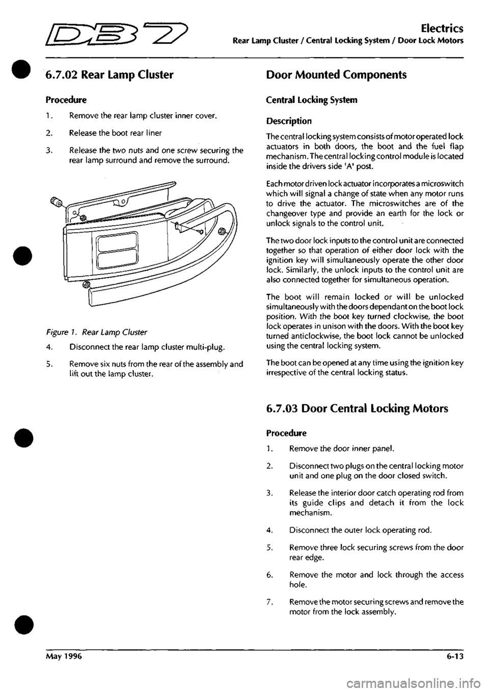
3. Release the two nuts and one screw securing the
rear lamp surround and remove the surround.
Figure 7. Rear Lamp Cluster
4.
Disconnect the rear lamp cluster multi-plug.
5. Remove six nuts from the rear of the assembly and
lift out the lamp cluster.
Central Locking System
Description
Thecentral locking system consistsofmotoroperated lock
actuators in both doors, the boot and the fuel flap
mechanism. The central locking control module is located
inside the drivers side 'A' post.
Each motordriven lock actuator incorporatesa microswitch
which will signal a change of state when any motor runs
to drive the actuator. The microswitches are of the
changeover type and provide an earth for the lock or
unlock signals to the control unit.
The two door lock inputs to the control unit are connected
together so that operation of either door lock with the
ignition key will simultaneously operate the other door
lock. Similarly, the unlock inputs to the control unit are
also connected together for simultaneous operation.
The boot will remain locked or will be unlocked
simultaneously with the doors dependant on the boot lock
position.
With the boot key turned clockwise, the boot
lock operates in unison with the doors. With the boot key
turned anticlockwise, the boot lock cannot be unlocked
using the central locking system.
The boot can be opened at any time using the ignition key
irrespective of the central locking status.
6.7.03 Door Central Locking Motors
Procedure
1.
Remove the door inner panel.
2.
Disconnect two plugs on the central locking motor
unit and one plug on the door closed switch.
3. Release the interior door catch operating rod from
its guide clips and detach it from the lock
mechanism.
4.
Disconnect the outer lock operating rod.
5. Remove three lock securing screws from the door
rear edge.
6. Remove the motor and lock through the access
hole.
7. Remove the motor securing screws and remove the
motor from the lock assembly.
May 1996 6-13
Page 200 of 421
Electrics
Airbag System [EE:^^^?
Continuous Airbag Warning Lamp
Inoperative lamp circuit or no ignition supply to the
airbag diagnostic module.
Normal Operation
The airbag warning lamp is designed to illuminate
for approximately six seconds when the ignition is
switched
on.
This period isallocated for satisfactory
performance of the airbag system self test. If after
this period, the diagnostic module detects a fault
within the system, the airbag warning lamp will
begin to flash.
Note:
The seat
belt
pretensioner system
(if fitted)
shares
the
airbag/SRS
warning lamp with
the airbag
system.
If a
seat belt pretensioner fault is
detected,
the
Airbag/SRS
warning lamp will be permanently illuminated. Ensure
thata permanently lit
lamp
is nottheresultof a pretensioner
fault before carrying out fault analysis on the airbag
system.
Poor connection or disconnection of the diagnostic
module harness may cause a short circuit from DM
pin 4 (warning lamp control) to pin 5 (ground) and
cause permanent illumination ofthe warning lamp.
Faulty operation of the diagnostic module internal
logic may fail to turn off the warning lamp control
circuit and cause constant illumination of the
warning lamp.
Fault Analysis
WARNING: Read and adhere to all warnings and
safety procedures at the start of this section when
working on the airbag system.
1.
Disarm the airbag system and fit airbag simulators
(6.4.21.4). Reconnect the battery.
2.
Inspectthe instrument pack and diagnostic module
connectors for damaged, pushed out pins, proper
location etc.
If any defects are identified, service as necessary.
Retest to ensure correct operation of the airbag
warning light.
If the connector condition and security are good,
reconnect the connectors and go to step 3.
5.
Connect the PDU to the upper diagnostic socket
and monitorthe airbag warning lamp
signal.
Switch
on the ignition.
If the signal is permanently low, suspect a short
circuit to ground on the airbag warning lamp
control line within the diagnostic module or from
diagnostic module pin
1
-4 to earth. Co to step 4.
If the signal switches low for six seconds after
ignition on but the airbag warning lamp is
permanently illuminated, suspect a fault in the
output side of the instrument pack to the airbag
warning lamp.
Disconnect diagnostic module plug 1 (slate) and
withdraw the plastic locking wedge to prevent
shorts to other circuits. Check continuity from pin
1-1 to ground.
If a short circuit to ground is detected, service the
wiring
as
necessary. Replacethe locking
wedge,
re
insert the connector. Switch on the ignition and
check that the airbag warning lamp signal atpin 1-
4 goes high six seconds after switching on the
ignition and that the warning lamp extinguishes.
If no short circuitto ground isdetected,thediagnostic
module is faulty. Replace the diagnostic module.
Switch on the ignition and check that the airbag
warning lamp signal at pin
1
-4 goes high six seconds
after switching on the ignition and that the warning
lamp extinguishes.
Switch off the ignition. Disconnect the battery.
Rearm the airbags (6.4.21.4). Switch on the
ign
ition
and check for correct indications from the airbag
warning lamp.
6-84 September 1996
Page 202 of 421

Electrics
Airbag System ^2?
Airbag DM Fault Code 13
Airbag circuit short to ground
Normal Operation
The diagnostic modu
le
measures the voltage at pins
2-5 and 2-6. The voltage at these pins is dependant
on charging system voltage as shown in the table
belovi-.
'in 2-5
2.3V
2.4 V
2.5V
2.7V
2.8V
3.0V
3.1V
3.2V
3.4V
3.5V
3.7V
3.8V
4.0V
4.1V
4.3V
Pin 2-6
2.3V
2.4V
2.5V
2.7V
2.8V
3.0V
3.1V
3.2V
3.4V
3.5V
3.7V
3.8V
4.0V
4.1V
4.3V
Charge Volts
9.0V
9.5V
lO.OV
10.5V
11.OV
11.5V
12.0V
12.5V
13.0V
13.5V
14.0V
14.5V
15.0V
15.5V
16.0V
If the diagnostic monitor measures a voltage of 2.0
volts or less on pins 2-5 and 2-6, a fau It code 13 will
be generated and flashed to the instrument pack to
be signalled on the airbag warning lamp. Voltages
as low as 2.0 volts indicate a possible short to
ground in these circuits.
When generating a code 13 the diagnostic module
also generates a signal to blow its own internal
thermal fuse. This action disables the airbag
deployment circuit. The airbag diagnostic module
fuse is non-repairable and the module must be
replaced after repairing the short circuit, if the
voltage at pins 2-5 and 2-6 returns to normal, fault
code 51 (blown thermal fuse) will be stored in
memory.
6.
Fault Analysis
WARNING: Read and adhere to all warnings and
safety procedures at the start of this section when
working on the airbag
system.
Disarm the airbag system and fit airbag simulators
(6.4.21.4)
Disconnect the airbag diagnostic module. Switch
on the ignition.
Measure the continuity to ground at the following
pins on the diagnostic module harness connector:
2-2 Passenger airbag feed
2-3 Passenger airbag return
2-4 Drivers airbag return
2-5 Drivers airbag feed
2-11 Safing sensor feed
If no short circuit is detected, go to step 4.
If
a
short circuit is detected, disconnect the relevant
airbag simulator or the safing sensor and repeat the
continuity measurement to isolate the circuit fault.
Service the wiring or replace the safing sensor as
necessary. Fit a new airbag diagnostic module and
rearm the airbags (6.4.21.4).
Check for intermittent short circuits in the cable
reel cassette. Monitor the continuity to ground at
pins 2-4 and 2-5 whilst rotating the steering from
lock to lock in both directions.
If no short circuit is detected, go to step 5.
If a short circuit is detected, replace the column
switchgear assembly. Fit a new airbag diagnostic
module and rearm the airbags (6.4.21.4).
WARNING: Do not attempt to make any electrical
measurements on the airbag
modules.
Any induced
voltage can
cause
the airbag
to
deploy with the
risk
of personal
injury.
Fit a replacement diagnostic module and
replacement airbag modules.
Caution: Do not refit
the
old
airbag
modules.
They may
be faulty and would
damage the
new diagnostic module.
Rearm the airbag system (6.4.21.4).
6-86 September 1996
Page 203 of 421
mxm^^^?
Electrics
Airbag System
Airbag DM Fault Code 14
Primary crash sensor circuit short to ground
Airbag DM Fault Code 21
Safing sensor insecure mounting.
Normal Operation
The diagnostic module measuresthevoltage at pins
1
-2 and
1
-6. The normal voltage at these pins is 10
volts (±1 volt) with the ignition on, and battery
voltage with the ignition off.
If the voltage at the airbag diagnostic module
connector pins
1
-2 or
1
-6 drops below 5 volts, fault
code 14 will be generated and the airbag warning
lamp will be switched on. When generating a code
14 the diagnostic module also generates a signal to
blow its own internal thermal fuse. This action
disables the airbag deployment circuit. The airbag
diagnostic module fuse is non-repairable and the
module must be replaced after removing the short
circuit. If the voltage at pins 1-2 and 1-6 returns to
normal,
fault code 51 (blown thermal fuse) will be
logged.
Fault Analysis
WARNING: Read and adhere to all warnings and
safety procedures at the start of
this
section when
working on the airbag system.
1.
Disarm the airbag system and fit airbag simulators
(6.4.21.4)
2.
Disconnect the airbag diagnostic module and
remove the plastic wedge from plug
1
(slate).
Note:
The
plastic wedge contains a shorting bar which
would
short
together pins
1-3
(gnd),
1-11
and 1-2 when
the plug is disconnected.
3 Measure the continuity to ground at the following
pins on the diagnostic module harness connector:
1-2 RH crash sensor monitor
1-11 LH crash sensor feed
1
-6 LH crash sensor monitor
1-12 RH crash sensor feed
If no short circuit is detected, go to step 4.
If a short circuit
is
detected, disconnect the relevant
crash sensorandrepeatthecontinuity measurement
to isolate the circuit fault. Service the wiring or
replace the crash sensor as necessary. Refit the
plastic wedge to the diagnostic module connector.
Fit a new airbag diagnostic module and rearm the
airbags (6.4.21.4).
Normal Operation
The diagnostic module measures the resistance
between pins
1
-10 (safing sensor case ground) and
1-3 (monitor reference ground) at the diagnostic
module connector. If the resistance is greater than
2Q
a
fault code
21
will be generated and the airbag
warning lamp will be switched on.
Note:
a
good ground connection is vital.
The
wire from
pin
1-1
is riveted to the safing
sensor case
and the
case
must
be securely
grounded to the vehicle
body.
Fault Analysis
WARNING: Read and adhere to all warnings and
safety procedures at the start of this section when
working on the airbag system.
Disarm the airbag system and fit airbag simulators
(6.4.21.4).
Disconnect the diagnostic connector and check for
continuity from pin 1-3 to chassis ground.
If continuity is good, go to step 3.
If the resistance reading is 2Q or more, service the
diagnostic module ground circuit to pin 1-3 as
necessary. Confirm a good ground path between
pins 1-10 and 1-3.Clearthecode21 and rearm the
airbags (6.4.21.4).
Check for continuity between pins
1
-10 and chassis
ground at the safing sensor.
If the resistance is above 2Q, check for continuity
from the safing sensor connector pin 5 to chassis
ground.
Also check the safing sensor mounting for
corrosion,
dirt or loose fixings. Service the wiring
and/or clean and secure the sensor mounting as
necessary, if a satisfactory ground is not achieved,
replace the safing sensor.
Make
a
final continuity test from diagnostic module
connector pin
1
-3 to
1
-10 to ensure a satisfactory
ground
path.
Reconnect the diagnostic module.
Clear the code
21.
Rearm the airbags (6.4.21.4).
September 1996 6-87
Page 262 of 421
y/--^^^^3^
'—-p "^ Body and Trim
Roof Description
Volante Roof
Description
The system comprises an electrically driven hydraulic pump and two hydraulic rams for raising and lowering the
roof.
The pump is powered via two heavy duty changeover relays. Two further pairs of changeover relays power
the rear quarter windows (one pair for each window). The roof hydraulic pump is protected by a 30A fuse, the
windows by circuit breakers.
An electronic control module (ECM) is actuated by the roof switch on the centre console. The ECM controls the
operation of
both
the roof
and
rear quarter window circuits
so
that they can only be operated in
a
pre-programmed
manned.
When in operation, the ECM provides signals to the roof and to the rear quarter windows.
When the roof
switch
is moved into the open (Roof Down) position, the roof
and
rear windows move together until
approximately four seconds has elapsed. At this time, the ECM will remove power from the rear window circuits,
leaving the roof motor running. The roof motor will stop after 12 seconds (i.e. a further 8 seconds after the rear
window motors stop).
The signals will be removed from the rear window relay after 4 seconds and from the roof relay after 12 seconds
if the roof switch is held in either position for longer than 12 seconds.
In order to comply with legislation, the following features are built into the system:
If the roof switch is operated in either direction and then released before that operation is complete, the roof and
rear quarter windows will stop immediately. If, whilst the system is in operation, the ignition switch
is
turned to the
off position, the system will immediately stop.
If the roof switch is pressed again after pausing during a roof movement, the timing sequence will be as follows:
1.
If the previous direction is selected, the timing recommences from where it left off and will continue to
completion. If the ignition has been turned off, the timing will start from the beginning of its cycle.
2.
If theoppositedirection
is
selected,
the timing sequence will commence
from the beginning
of the newly selected
direction and continue to completion.
Roof and Rear Quarter Light Control
The following diagrams show the component location and the electrical control for the roof and rear quarter light
systems.
May 1996 7-7
Page 297 of 421
Air Conditioning
Electronic Control Module r^^?
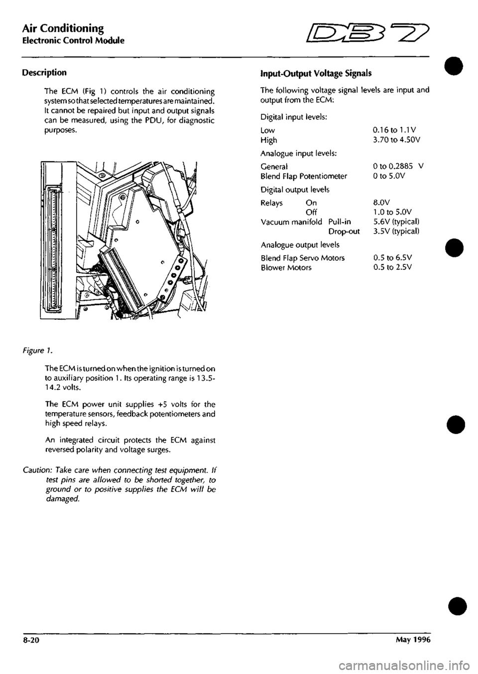
Description
The ECM (Fig 1) controls the air conditioning
system so that selected temperaturesare maintained.
It cannot be repaired but input and output signals
can be measured, using the PDU, for diagnostic
purposes.
Input-Output Voltage Signals
The following voltage signal levels are input and
output from the ECM:
Digital input levels:
Low
High
Analogue input levels:
General
Blend Flap Potentiometer
Digital output levels
Relays On
Off
Vacuum manifold Pull-in
Drop-out
Analogue output levels
Blend Flap Servo Motors
Blower Motors
0.16 to 1.1V
3.70 to 4.50V
0 to 0.2885 V
0 to 5.0V
8.0V
1.0 to 5.0V
5.6V (typical)
3.5V (typical)
0.5 to 6.5V
0.5 to 2.5V
figure 1.
The ECM
is
turned on when the ignition
is
turned on
to auxiliary position 1. its operating range is 13.5-
14.2 volts.
The ECM power unit supplies +5 volts for the
temperature sensors, feedback potentiometers and
high speed relays.
An integrated circuit protects the ECM against
reversed polarity and voltage surges.
Caution: Take care when connecting test equipment. If
test pins are allowed to be shorted together, to
ground or to positive supplies the ECM will be
damaged.
8-20 May 1996
Page 300 of 421
'^^p
Air Conditioning
In Car Controls
Fan Speed Control Switch (Mode Switch)
SC On Mode
The system is not operational, a residual
signal to the ECM ensures that the blower
flaps are closed to prevent air entering the
system.
1.
Low Blower Mode
The fan speed is lowandtheairconditioning
function switch is fully operational. Pin 13
on the ECM is earthed through the switch
and a 12V signal is returned to Pin 44.
2.
Medium Blower Mode
The fan runs at medium speed and the
function switch is fully operational. Pin 14
of the ECM is earthed through the switch
and a 12V signal is returned to Pin 44.
3. High Blower Mode
The fan speed is high and the function
switch is fully operational. Pin 15 at the
ECM is earthed through the switch and a
12V signal is returned to Pin 44.
DEF Defrost Blower Mode
The fan speed is
high,
the function switch
and temperature switch are not operational,
front screen vents are fully open and lower
flaps are fully closed. Pin 27 at the ECM is
earthed through the switch and a 12V signal
is returned to Pin 44.
Temperature Sensors
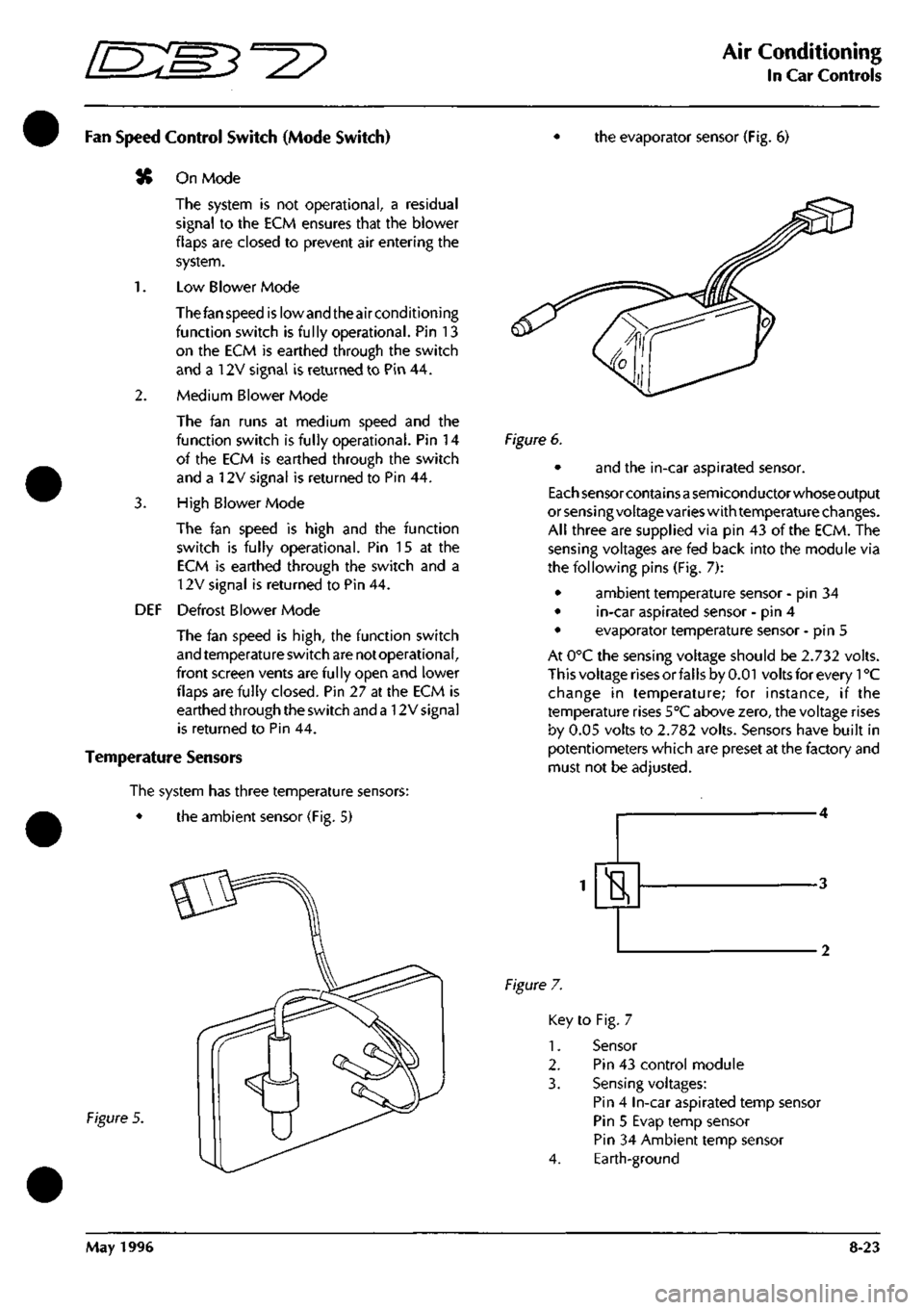
The system has three temperature sensors:
• the ambient sensor (Fig. 5)
the evaporator sensor (Fig. 6)
Figure 5.
Figure 6.
• and the in-car aspirated sensor.
Each sensor containsa semiconductor whose output
or sensing voltage varies with temperature changes.
All three are supplied via pin 43 of the ECM. The
sensing voltages are fed back into the module via
the following pins (Fig. 7):
• ambient temperature sensor - pin 34
• in-car aspirated sensor - pin 4
• evaporator temperature sensor - pin 5
At 0°C the sensing voltage should be 2.732 volts.
This voltage rises or falls by 0.01 volts for every 1°C
change in temperature; for instance, if the
temperature rises 5°C above zero, the voltage rises
by 0.05 volts to 2.782 volts. Sensors have built in
potentiometers which are preset at the factory and
must not be adjusted.
H
Figure 7.
Key to Fig. 7
1.
Sensor
2.
Pin 43 control module
3. Sensing voltages:
Pin 4 In-car aspirated temp sensor
Pin 5 Evap temp sensor
Pin 34 Ambient temp sensor
4.
Earth-ground
May 1996 8-23
Page 303 of 421
Air Conditioning
Lower Feedback Potentiomenter "3^^?
Blower Motors Potentiometers
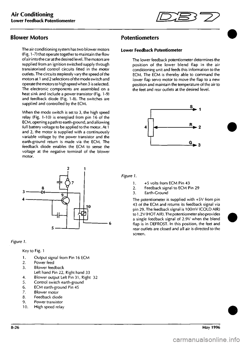
The air conditioning system has two blower motors
(Fig.
1
-7) that operate together to maintain the flow
of air into the car at the desired
level.
The motors are
supplied from an ignition switched supply through
transistorised control circuits fitted in the motor
outlets. The circuits steplessly vary the speed of the
motors at
1
and 2 selections of the mode switch and
operate the motors to high speed when 3
is
selected.
The electronic components are assembled on a
heat sink and include a power transistor (Fig.
1
-9)
and feedback diode (Fig. 1-8). The switches are
supplied and controlled by the ECM.
When the mode switch is set to 3, the high speed
relay (Fig. 1-10) is energised from pin 16 of the
ECM,
opening
a
path to earth-ground, and allowing
full battery voltage to be applied to the motor. At 1
and 2, the motor is supplied with a continuously
variable voltage by the power transistor and the
earth-ground return is made via the ECM. The
feedback diode enables the ECM to sense the
voltage at the negative terminal of the blower
motor.
Lower Feedback Potentiometer
The lower feedback potentiometer determines the
position of the lower blend flap in the air
conditioning unit and feeds this information to the
ECM.
The ECM is thereby able to command the
lower flap servo motor to move the flap to a new
position and maintain the temperature of the air to
the feet and rear outlets at the desired level.
V 1
• 2
V3
Figure 1.
Key to Fig. 1
1.
Output signal from Pin 16 ECM
2.
Power feed
3. Blower feedback
Left hand Pin 22, Right hand 33
4.
Blower output Left Pin 31, Right 32
5. Control switch earth-ground
6. ECM earth-ground Pin 45
7. Blower motor
8. Feedback diode
9. Power transistor
10.
High speed relay
Figure 1.
1.
2.
3.
+5 volts from ECM Pin 43
Feedback signal to ECM Pin 29
Earth-Ground
The potentiometer is supplied with +5V from pin
43 of the ECM and returns its feedback signal via
pin 29. The feedback signal is 10OmV (COLD AIR)
to 1.2 V (HOT A!
R).
The potentiometer also provides
a single feedback signal of 2.9V when the blend
flap is in DEFROST. In this position, the feet and
rear outlets are closed and all air is directed to the
screen.
8-26 May 1996
Page 304 of 421
^?
Air Conditioning
Upper Feedback Potentiometer / Servo Motors
Upper Feedback Potentiometer
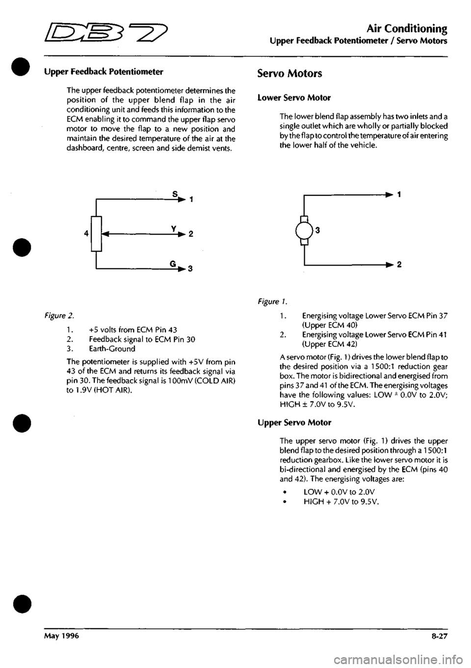
The upper feedback potentiometer determines the
position of the upper blend flap in the air
conditioning unit and feeds this information to the
ECM enabling it to command the upper flap servo
motor to move the flap to a new position and
maintain the desired temperature of the air at the
dashboard,
centre, screen and side demist vents.
Servo Motors
Lower Servo Motor
The lower blend flap assembly has two inlets and a
single outlet which are wholly or partially blocked
by the flap to control the temperature of air entering
the lower half of the vehicle.
V 1
-•2
V3 -•2
Figure
2.
1.
2.
3.
+5 volts from ECM Pin 43
Feedback signal to ECM Pin 30
Earth-Ground
The potentiometer is supplied with +5V from pin
43 of the ECM and returns its feedback signal via
pin 30. The feedback signal is
1
OOmV (COLD AIR)
to 1.9V (HOT AIR).
Figure L
1.
Energising voltage Lower Servo ECM Pin 37
(Upper ECM 40)
2.
Energising voltage Lower Servo ECM Pin 41
(Upper ECM 42)
A servo motor
(Fig.
1) drives the lower blend flap to
the desired position via a 1500:1 reduction gear
box. The motor is bidirectional and energised from
pins 37 and
41
of the
ECM.
The energising voltages
have the following values: LOW ± O.OV to 2.0V;
HIGH± 7.0V to 9.5V.
Upper Servo Motor
The upper servo motor (Fig. 1) drives the upper
blend flap to the desired position through a 1500:1
reduction gearbox. Like the lower servo motor it is
bi-directional and energised by the ECM (pins 40
and 42). The energising voltages are:
LOW + O.OV to 2.0V
HIGH + 7.0V to 9.5V.
May 1996 8-27
Page 312 of 421
'^T?
Air Conditioning
Compressors
Compressors
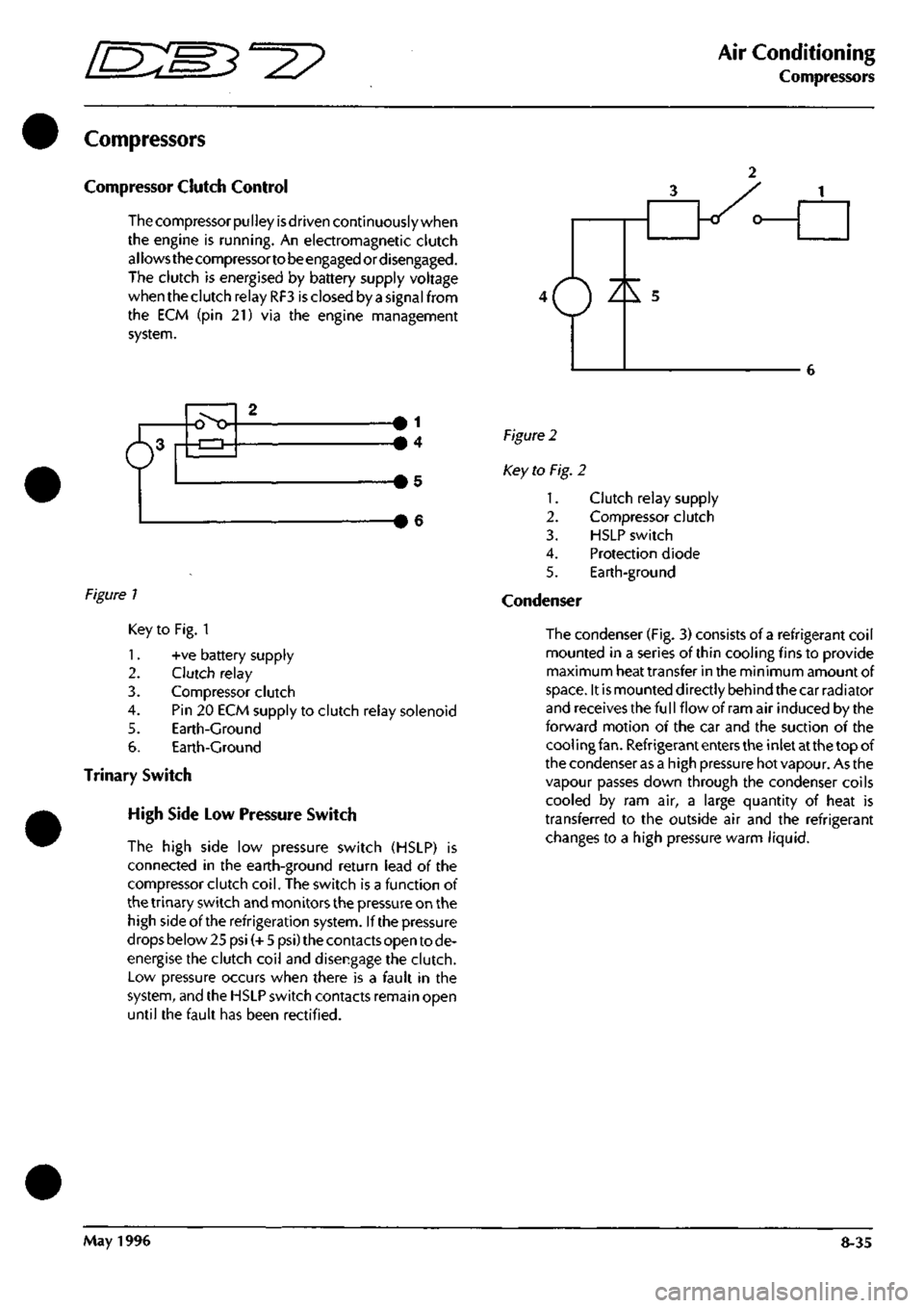
Compressor Clutch Control
The compressor
pu I
ley
is
driven continuously when
the engine is running. An electromagnetic clutch
allows the compressortobeengagedordisengaged.
The clutch is energised by battery supply voltage
when the clutch relay RF3 is closed by a signal from
the ECM (pin 21) via the engine management
system.
6^
o>o 1
4
Figure 1
Figure 2
Key to Fig. 2
1.
2.
3.
4.
5.
Condenser
Clutch relay supply
Compressor clutch
HSLP switch
Protection diode
Earth-ground
Key to Fig. 1
1.
+ve battery supply
2.
Clutch relay
3. Compressor clutch
4.
Pin 20 ECM supply to clutch relay solenoid
5. Earth-Ground
6. Earth-Ground
Trinary Switch
High Side Low Pressure Switch
The high side low pressure switch (HSLP) is
connected in the earth-ground return lead of the
compressor clutch
coil.
The switch is a function of
the trinary switch and monitors the pressure on the
high side of the refrigeration system. If the pressure
drops below 25 psi (+ 5 psi) the contacts open to de-
energise the clutch coil and disengage the clutch.
Low pressure occurs when there is a fault in the
system,
and the HSLP switch contacts remain open
until the fault has been rectified.
The condenser (Fig, 3) consists of a refrigerant coil
mounted in a series of thin cooling fins to provide
maximum heat transfer in the minimum amount of
space.
It is mounted directly behind the car radiator
and receives the fu
11
flow of ram air induced by the
forward motion of the car and the suction of the
cool ing
fan.
Refrigerant enters the inlet at the top of
the condenser as a high pressure hot vapour. As the
vapour passes down through the condenser coils
cooled by ram air, a large quantity of heat is
transferred to the outside air and the refrigerant
changes to a high pressure warm liquid.
May 1996 8-35