tyre pressure ASTON MARTIN DB7 1997 Workshop Manual
[x] Cancel search | Manufacturer: ASTON MARTIN, Model Year: 1997, Model line: DB7, Model: ASTON MARTIN DB7 1997Pages: 421, PDF Size: 9.31 MB
Page 111 of 421

Electrics
Component Index Sheet 4-97 MY ^7
Component
Name
Relay - Rear Fog Lamps
Relay - Reverse Lamps
Relay - Right Quarter Light Up
Relay - Right Quarter Light Down
Relay - Sidelights {
Relay - Starter Solenoid
Relay - Stop Lamps
Relay- Tilt Sensor
Reversing Light Switch
Screen Wash Pump
Seat Belt Stalk
Seat Belt Pretensioner Control Module
Seat Belt Pretensioner Squib
Seat ECU - Driver
Seat ECU - Passenger
Seat Fore/Aft Motor Potentiometer
Seat Heater Cushion Element
Seat Heaters - Driver
Seat Heaters - Passenger
Seat Lumbar Support Pump
Seat Pressure Pad
Seat Recline Motor Potentiometer
Seat Switch Pack - Driver
Seat Switch Pack - Passenger
Security System Aerial
Security System ECU
Side Marker Lamp - LH Front
Side Marker Lamp - RH Front
Side Marker Lamp - LH Rear
Side Marker Lamp - RH Rear
Side Repeater Lamp LH
Side Repeater Lamp RH
Speaker - Drivers Door
Speaker - Passengers Door
Speaker - Rear LH
Speaker - Rear RH
Starter Motor Solenoid
Throttle Potentiometer (Eng Sub-harness)
Tilt Sensor
Transmission Connector
Transmission Control Module (TCM)
Transmission Input Speed Sensor
Transmission Output Speed Sensor
Tyre Compressor Socket
Vapour Management Valve
Vehicle Speed Sensor (VSS)
Window ECU - Drivers Side
Window ECU - Passengers Side
Window Lift - Left Quarter Light (Volante)
Window Lift Thermal Breaker
Window Switch LH
Window Switch RH
Wiper Logic Module
Wiper Motor
6-46
Component
Location
Circuit
Reference
(see relay location chart) 8-C4 it ti It
II H U
tl 11 U
a II 11
II II II
II Ji II
II II II
7-7
15-1
15-9
4-4
15-5
4-6
4-6
15-10
7-11
7-n
7-11
16-4
7-10
15-10
7-3
7-3
16-10
4-5
16-1
16-2
16-6
16-8
13-1
13-4
5-3
5-3
5-6
5-6
3-10
3-7
7-9
16-5
4-7
17-7
17-7
17-5
15-7
8-5
6-3
6-3
17-4
6-4
17-1
17-3
7-2
17-2
' ) 17-A2
' ) 19-A4
' ) 19-A5
' ) 2-A1
' ) 2-A3
' ) 17-A1
' ) 17-A4
7-C5
3-A2
26-A3
14-A4
14-B4
23-A1
24-A1
26-C2
26-A2
23-A4
24-A4
26-D2
26-D3
26-B1
23-B1
24-B1
16-B2
17-B6
1-C2
1-82
15-C4
24-D4
2-C5
3-D5
21-C5
22-C5
15-Cl
16-B1
2-A5
5-C3
14-C4
7-A4
4-B5
7-B2
7-B3
17-C5
16-A3
15-B3
21-C3
22-C3
15-A1
12-Cl
13-C2
13-A2
11-B5
6-A1
September 1996
Page 394 of 421

^?
The Aston Martin Lagonda Diagnostic System
Users Guide
Climate Control Diagnostics
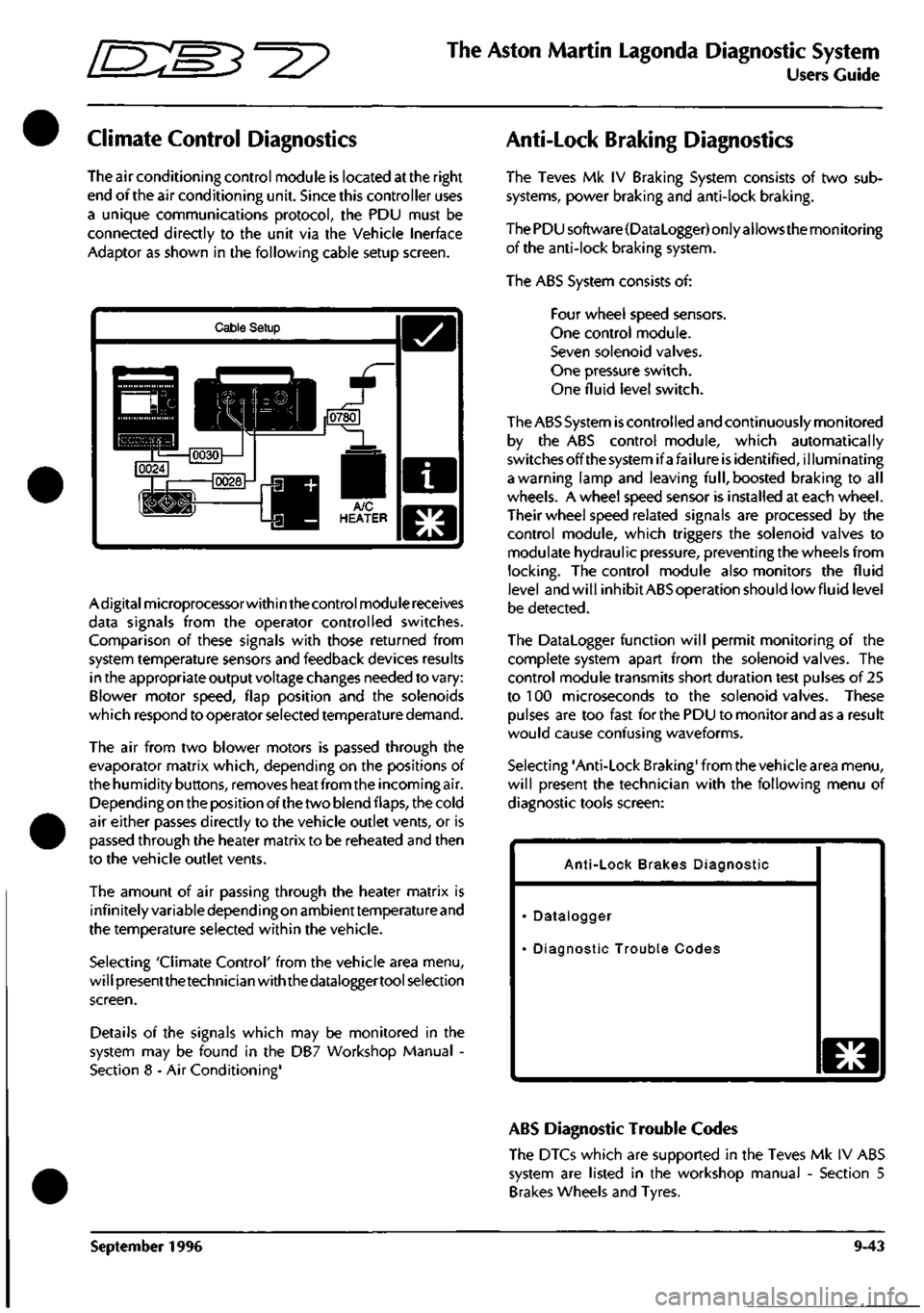
The air conditioning control module is located at the right
end of the air conditioning unit. Since this controller uses
a unique communications protocol, the PDU must be
connected directly to the unit via the Vehicle Inerface
Adaptor as shown in the following cable setup screen.
Cable Setup
Adigitalmicroprocessorwithin the control module receives
data signals from the operator controlled switches.
Comparison of these signals with those returned from
system temperature sensors and feedback devices results
in the appropriate output voltage changes needed to vary:
Blower motor speed, flap position and the solenoids
which respond to operator selected temperature demand.
The air from two blower motors is passed through the
evaporator matrix which, depending on the positions of
the humidity buttons, removes heat from the incoming air.
Dependingon the position of the two blend flaps, the cold
air either passes directly to the vehicle outlet vents, or is
passed through the heater matrix to be reheated and then
to the vehicle outlet vents.
The amount of air passing through the heater matrix is
infinitely variable depending on ambienttemperature and
the temperature selected within the vehicle.
Selecting 'Climate Control' from the vehicle area menu,
will presentthetechnician with the dataloggertool selection
screen.
Details of the signals which may be monitored in the
system may be found in the DB7 Workshop Manual -
Section 8 - Air Conditioning'
Anti-Lock Braking Diagnostics
The Teves Mk IV Braking System consists of two sub
systems, power braking and anti-lock braking.
The PDU software(DataLogger) only allows the monitoring
of the anti-lock braking system.
The ABS System consists of:
Four wheel speed sensors.
One control module.
Seven solenoid valves.
One pressure switch.
One fluid level switch.
The ABS System
is
controlled and continuously monitored
by the ABS control module, which automatically
switchesoffthesystemifafailure is identified, illuminating
a warning lamp and leaving
full,
boosted braking to all
wheels. A wheel speed sensor is installed at each wheel.
Their wheel speed related signals are processed by the
control module, which triggers the solenoid valves to
modulate hydraulic pressure, preventing the wheels from
locking.
The control module also monitors the fluid
level and will inhibit ABS operation should lowfluid level
be detected.
The Datalogger function will permit monitoring of the
complete system apart from the solenoid valves. The
control module transmits short duration test pulses of 25
to 100 microseconds to the solenoid valves. These
pulses are too fast for the PDU to monitor and as a result
would cause confusing waveforms.
Selecting 'Anti-Lock Braking' from the vehicle area menu,
will present the technician with the following menu of
diagnostic tools screen:
Anti-Lock Brakes Diagnostic
Datalogger
Diagnostic Trouble Codes
o
ABS Diagnostic Trouble Codes
The DTCs which are supported in the Teves Mk IV ABS
system are listed in the workshop manual - Section 5
Brakes Wheels and Tyres.
September 1996 9-43