seats ASTON MARTIN V8 VANTAGE 2010 User Guide
[x] Cancel search | Manufacturer: ASTON MARTIN, Model Year: 2010, Model line: V8 VANTAGE, Model: ASTON MARTIN V8 VANTAGE 2010Pages: 947, PDF Size: 43.21 MB
Page 436 of 947

Rear Suspension (04.02)
Suspension (04.00)4-2-2 Workshop Manual May 2007
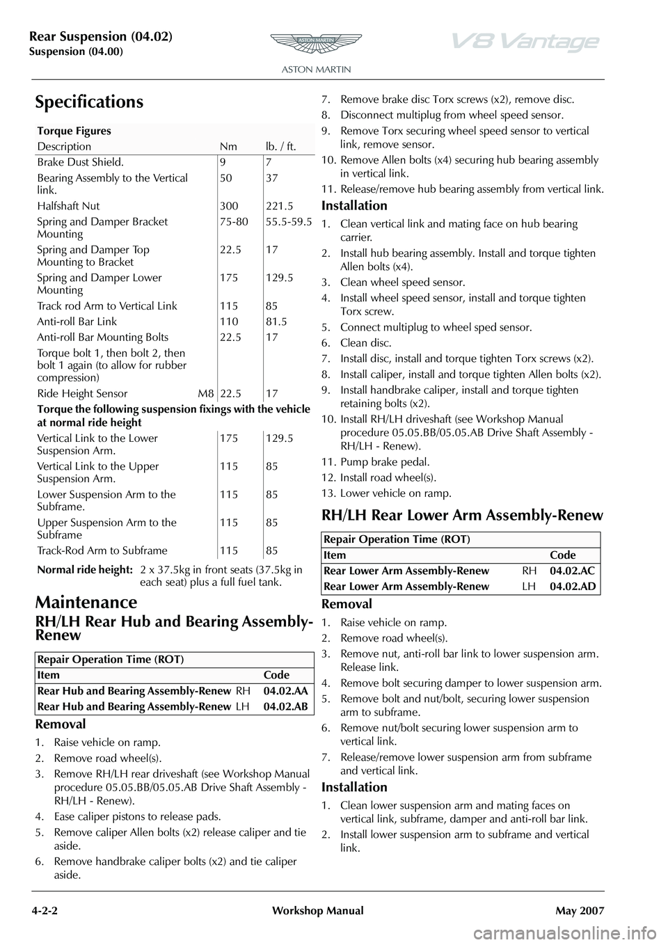
Specifications
Maintenance
RH/LH Rear Hub and Bearing Assembly-
Renew
Removal
1. Raise vehicle on ramp.
2. Remove road wheel(s).
3. Remove RH/LH rear drivesha ft (see Workshop Manual
procedure 05.05.BB/05.05.AB Drive Shaft Assembly -
RH/LH - Renew).
4. Ease caliper pistons to release pads.
5. Remove caliper Allen bolts (x2) release caliper and tie aside.
6. Remove handbrake caliper bolts (x2) and tie caliper aside. 7. Remove brake disc Torx screws (x2), remove disc.
8. Disconnect multiplug fr
om wheel speed sensor.
9. Remove Torx securing wheel speed sensor to vertical link, remove sensor.
10. Remove Allen bolts (x4) se curing hub bearing assembly
in vertical link.
11. Release/remove hub bearing a ssembly from vertical link.
Installation
1. Clean vertical link and mating face on hub bearing
carrier.
2. Install hub bearing assembly. Install and torque tighten Allen bolts (x4).
3. Clean wheel speed sensor.
4. Install wheel speed sensor, install and torque tighten Torx screw.
5. Connect multiplug to wheel sped sensor.
6. Clean disc.
7. Install disc, install and torq ue tighten Torx screws (x2).
8. Install caliper, install and torque tighten Allen bolts (x2).
9. Install handbrake caliper, install and torque tighten
retaining bolts (x2).
10. Install RH/LH driveshaft (see Workshop Manual
procedure 05.05.BB/05.05.AB Drive Shaft Assembly -
RH/LH - Renew).
11. Pump brake pedal.
12. Install road wheel(s).
13. Lower vehicle on ramp.
RH/LH Rear Lower Arm Assembly-Renew
Removal
1. Raise vehicle on ramp.
2. Remove road wheel(s).
3. Remove nut, anti-roll bar li nk to lower suspension arm.
Release link.
4. Remove bolt securing damper to lower suspension arm.
5. Remove bolt and nut/bolt, securing lower suspension arm to subframe.
6. Remove nut/bolt securing lower suspension arm to
vertical link.
7. Release/remove lower suspension arm from subframe and vertical link.
Installation
1. Clean lower suspension arm and mating faces on vertical link, subframe, damper and anti-roll bar link.
2. Install lower suspension ar m to subframe and vertical
link.
Torque Figures
DescriptionNmlb. / ft.
Brake Dust Shield. 9 7
Bearing Assembly to the Vertical
link. 50 37
Halfshaft Nut 300 221.5
Spring and Damper Bracket
Mounting 75-80 55.5-59.5
Spring and Damper Top
Mounting to Bracket 22.5 17
Spring and Damper Lower
Mounting 175 129.5
Track rod Arm to Vertical Link 115 85
Anti-roll Bar Link 110 81.5
Anti-roll Bar Mounting Bolts
Torque bolt 1, then bolt 2, then
bolt 1 again (to allow for rubber
compression) 22.5 17
Ride Height Sensor M8 22.5 17
Torque the following suspensi on fixings with the vehicle
at normal ride height
Vertical Link to the Lower
Suspension Arm. 175 129.5
Vertical Link to the Upper
Suspension Arm. 115 85
Lower Suspension Arm to the
Subframe. 115 85
Upper Suspension Arm to the
Subframe 115 85
Track-Rod Arm to Subframe 115 85
Normal ride height: 2 x 37.5kg in front seats (37.5kg in
each seat) plus a full fuel tank.
Repair Operation Time (ROT)
Repair Operation Time (ROT)
ItemCode
Rear Lower Arm Assembly-Renew RH04.02.AC
Rear Lower Arm Assembly-Renew LH04.02.AD
Page 453 of 947

Road Wheels and Tyres (04.04)
Suspension (04.00)
May 2007 Workshop Manual 4-4-3
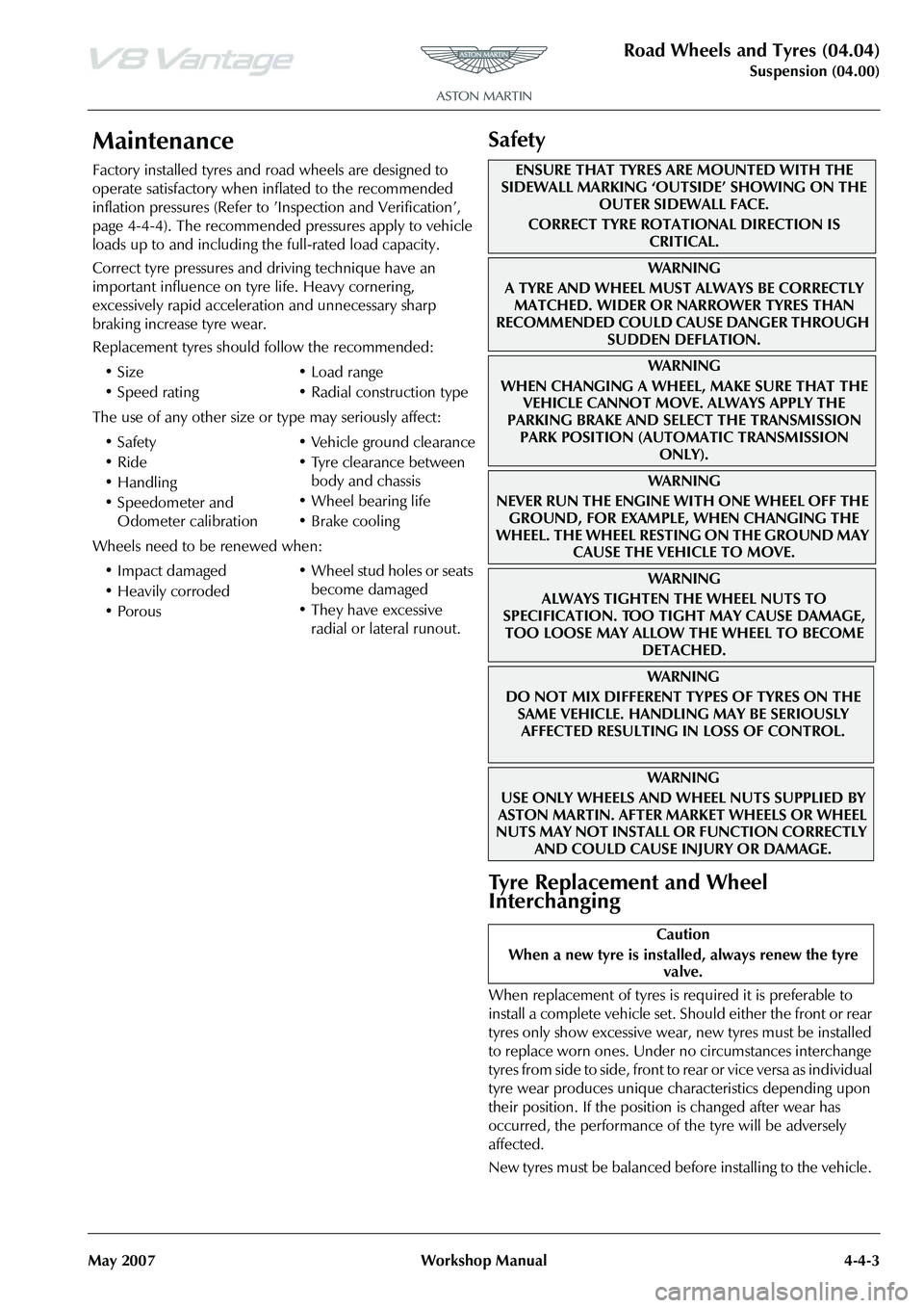
Maintenance
Factory installed tyres and road wheels are designed to
operate satisfactory when inflated to the recommended
inflation pressures (Refer to ’Inspection and Verification’,
page 4-4-4). The recommended pressures apply to vehicle
loads up to and including the full-rated load capacity.
Correct tyre pressures and driving technique have an
important influence on tyre life. Heavy cornering,
excessively rapid acceleration and unnecessary sharp
braking increase tyre wear.
Replacement tyres should follow the recommended:
The use of any other size or type may seriously affect:
Wheels need to be renewed when:
Safety
Tyre Replacement and Wheel
Interchanging
When replacement of tyres is required it is preferable to
install a complete vehicle set. S hould either the front or rear
tyres only show excessive wear, new tyres must be installed
to replace worn ones. Under no circumstances interchange
tyres from side to side, front to re ar or vice versa as individual
tyre wear produces unique characteristics depending upon
their position. If the position is changed after wear has
occurred, the performance of the tyre will be adversely
affected.
New tyres must be balanced before installing to the vehicle.
•Size
•Speed rating
•Load range
• Radial construction type
•Safety
•Ride
•Handling
• Speedometer and Odometer calibration • Vehicle ground clearance
• Tyre clearance between
body and chassis
• Wheel bearing life
• Brake cooling
• Impact damaged
• Heavily corroded
• Porous • Wheel stud holes or seats
become damaged
• They have excessive radial or lateral runout.
ENSURE THAT TYRES ARE MOUNTED WITH THE
SIDEWALL MARKING ‘OUTSIDE’ SHOWING ON THE
OUTER SIDEWALL FACE.
CORRECT TYRE ROTATIONAL DIRECTION IS CRITICAL.
WA R N I N G
A TYRE AND WHEEL MUST ALWAYS BE CORRECTLY MATCHED. WIDER OR NARROWER TYRES THAN
RECOMMENDED COULD CAUSE DANGER THROUGH
SUDDEN DEFLATION.
WA R N I N G
WHEN CHANGING A WHEEL, MAKE SURE THAT THE VEHICLE CANNOT MOVE. ALWAYS APPLY THE
PARKING BRAKE AND SELE CT THE TRANSMISSION
PARK POSITION (AUTOMATIC TRANSMISSION ONLY).
WA R N I N G
NEVER RUN THE ENGINE WITH ONE WHEEL OFF THE GROUND, FOR EXAMPLE, WHEN CHANGING THE
WHEEL. THE WHEEL RESTING ON THE GROUND MAY CAUSE THE VEHICLE TO MOVE.
WA R N I N G
ALWAYS TIGHTEN THE WHEEL NUTS TO
SPECIFICATION. TOO TIGHT MAY CAUSE DAMAGE,
TOO LOOSE MAY ALLOW TH E WHEEL TO BECOME
DETACHED.
WAR NI NG
DO NOT MIX DIFFERENT TY PES OF TYRES ON THE
SAME VEHICLE. HANDLING MAY BE SERIOUSLY AFFECTED RESULTING IN LOSS OF CONTROL.
WAR NI NG
USE ONLY WHEELS AND WHEEL NUTS SUPPLIED BY
ASTON MARTIN. AFTER MARKET WHEELS OR WHEEL
NUTS MAY NOT INSTALL OR FUNCTION CORRECTLY
AND COULD CAUSE INJURY OR DAMAGE.
Caution
When a new tyre is installe d, always renew the tyre
valve.
Page 692 of 947

Wiring and Circuit Protection (18.01)
Electric Distribution/Electronic Control (18.00)
May 2007 Workshop Manual 18-1-3
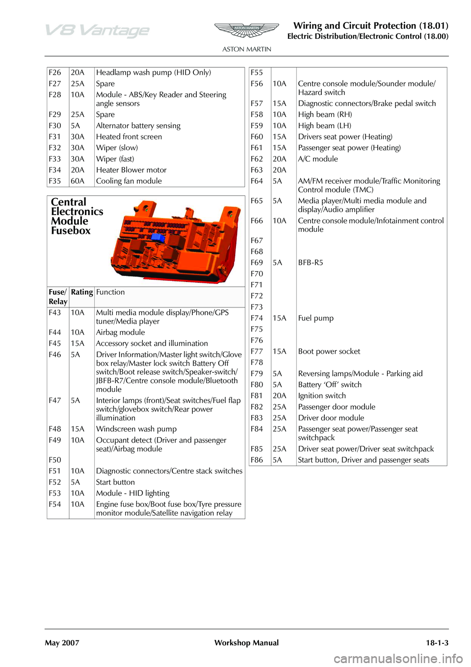
F26 20A Headlamp wash pump (HID Only)
F27 25A Spare
F28 10A Module - ABS/Key Reader and Steering angle sensors
F29 25A Spare
F30 5A Alternator battery sensing
F31 30A Heated front screen
F32 30A Wiper (slow)
F33 30A Wiper (fast)
F34 20A Heater Blower motor
F35 60A Cooling fan module
Central
Electronics
Module
Fusebox
Fuse/
RelayRatingFunction
F43 10A Multi media module display/Phone/GPS tuner/Media player
F44 10A Airbag module
F45 15A Accessory socket and illumination
F46 5A Driver Information/Master light switch/Glove box relay/Master lock switch Battery Off
switch/Boot release switch/Speaker-switch/
JBFB-R7/Centre console module/Bluetooth
module
F47 5A Interior lamps (front)/Seat switches/Fuel flap switch/glovebox switch/Rear power
illumination
F48 15A Windscreen wash pump
F49 10A Occupant detect (Driver and passenger seat)/Airbag module
F50
F51 10A Diagnostic connectors/Centre stack switches
F52 5A Start button
F53 10A Module - HID lighting
F54 10A Engine fuse box/Boot fuse box/Tyre pressure monitor module/Satellite navigation relay
F55
F56 10A Centre console module/Sounder module/
Hazard switch
F57 15A Diagnostic connectors/Brake pedal switch
F58 10A High beam (RH)
F59 10A High beam (LH)
F60 15A Drivers seat power (Heating)
F61 15A Passenger seat power (Heating)
F62 20A A/C module
F63 20A
F64 5A AM/FM receiver module/Traffic Monitoring Control module (TMC)
F65 5A Media player/Multi media module and display/Audio amplifier
F66 10A Centre console module/Infotainment control module
F67
F68
F69 5A BFB-R5
F70
F71
F72
F73
F74 15A Fuel pump
F75
F76
F77 15A Boot power socket
F78
F79 5A Reversing lamps/Module - Parking aid
F80 5A Battery ‘Off’ switch
F81 20A Ignition switch
F82 25A Passenger door module
F83 25A Driver door module
F84 25A Passenger seat power/Passenger seat switchpack
F85 25A Driver seat power/Driver seat switchpack
F86 5A Start button, Driver and passenger seats
Page 694 of 947

Wiring and Circuit Protection (18.01)
Electric Distribution/Electronic Control (18.00)
May 2007 Workshop Manual 18-1-5
The symbol for the screen is an oval with the wires that are
to be screened inside it. The letters ‘SCR’ define the screen.
Controller Area Network (CAN)
Controller Area Network (CAN) is the wiring between
intelligent modules of the vehi cle. This wiring carries the
electronic data around the vehicle allowing the various
modules and components to interrogate the network and
read their specific data signals.
There are 2 different speeds of network.
Low speed - Transmits at 125,000 bits per second. Mainly
for body controller systems such as seats and doors
High speed - Transmits at 500,000 bits per second. Mainly
for engine management and powertrain associated systems
such as ABS.
All wiring in the CAN is twisted. The twisted wires always
consist of one wire with a black trace in it for the negative
side and one with a brown trace in it for the positive.
High Speed CAN wire
Low Speed CAN wire
The symbol below shows a module or a component
connector with the pin numbers that have CAN wires
coming from them.
‘CAN LS+’ - Low speed CAN positive side
‘CAN LS-’ - Low speed CAN Negative Side
To aid identification of the different speed CAN’s in the
vehicle different colours of wi re have been used, e.g. the
Low Speed Volcano is GB twisted with GN, the High Speed
Volcano is RB twisted with RN.
There is attached on a separate page a list for wire colour
abbreviations and what colour they refer to.
205 U MABC 05
Wire No.
Colour
MAB (Defines Screened)
Size
Page 788 of 947

Squeaks and Rattles Repair Manual
Page 4 of 21 Issue 3
Evaluation Drives - Squeak & Rattle Feedback Guidelines
When you evaluate the vehicle, please make comments ab out all Squeak and Rattle problems that you find. Do
this if the problem is caused by dynamic road in puts or the functional operation of components.
Please give as much data as possible about the incident to help the analysis of the cause. If possible include the
data that follows in your comments:
• The noise type (refer to the examples that follow)
• The specific area of the vehicle (Lest side / Right side, Underbody, Parcel shelf, Rear environment,
Doors / Casings, Seats, Header, IP, Front End)
• The road surface (Broken tarmac, Motorway - co ncrete or tarmac, Cobblestones, Gravel etc.)
• A specific road input (Painted lines, cats-eyes or speed bumps)
• The vehicle temperature (Ambient / Cold / Hot, or the specific temperature in °C)
• The vehicle speed.