carpet ASTON MARTIN V8 VANTAGE 2010 Workshop Manual
[x] Cancel search | Manufacturer: ASTON MARTIN, Model Year: 2010, Model line: V8 VANTAGE, Model: ASTON MARTIN V8 VANTAGE 2010Pages: 947, PDF Size: 43.21 MB
Page 11 of 947
Vehicle Identification Number
Issue 5, January 2010 Workshop Manual 0-0-11
Vehicle Identification Number
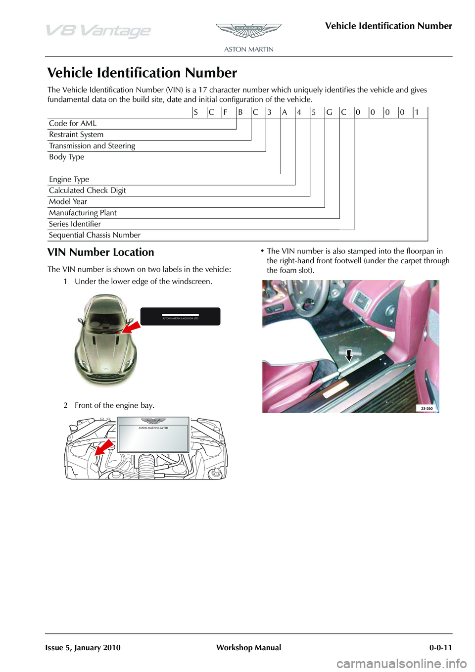
The Vehicle Identification Number (VIN) is a 17 character number which uniquely identifies the vehicle and gives
fundamental data on the build site, date and initial configuration of the vehicle.
VIN Number Location
The VIN number is shown on two labels in the vehicle:
1 Under the lower edge of the windscreen.
2 Front of the engine bay. • The VIN number is also stamped into the floorpan in
the right-hand front footwell (under the carpet through
the foam slot).
S CFBC3A45GC00001
Code for AML
Restraint System
Transmission and Steering
Body Type
Engine Type
Calculated Check Digit
Model Year
Manufacturing Plant
Series Identifier
Sequential Chassis Number
Page 13 of 947
Issue 5, January 2010 Workshop Manual 1-1-1
Body System (01.00)
Contents
Body Structure (01.01)........................................... 1-1-4Overview ................................................................ 1-4
Specifications.......................................................... 1-4
Maintenance ........................................................... 1-5Right Side Front Crush Bar for the Body
Reinforcement - Remove and Install ....................... 1-5
Left Side Front Crush Bar for the Body
Reinforcement - Remove and Install ....................... 1-5
Front Crush Brace - Remove and Install .................. 1-5
Front End (01.02) ................................................... 1-2-1 Front Wings ............................................................ 2-1Specifications ......................................................... 2-1
Maintenance ........................................................... 2-1 Radiator Closing Panel - Remove and Install ........... 2-1
Centre Undertray - Remove and Install
(Roadster Only) ..................................................... 2-1
Front Undertray-Remove and Install ....................... 2-2
Rear Undertray - Renew (Coupe only).................... 2-2
Rear Undertray - Renew (Roadster only) ................ 2-2
Install ..................................................................... 2-2.............................................................................. 2-2
Undertray, Vehicle Set - Renew ............................. 2-2
RH/LH Front Wheel Arch Liner - Renew ................ 2-2
RH/LH Rear Wheel Arch Liner - Renew ................. 2-3
RH Front Wing Panel Assembly - Renew ................ 2-4
LH Front Wing Panel Assembly - Renew ................ 2-6
Body Closures (01.03) ........................................... 1-3-1 Specifications.......................................................... 3-1Doors .................................................................... 3-1
Tailgate .................................................................. 3-1
Bonnet................................................................... 3-2
Maintenance ........................................................... 3-2 LH/RH Door Assembly-Renew ............................... 3-2
RH/LH Door Assembly-Remove/Refit ..................... 3-6
Front Door Hinge (One Side) - Renew ................... 3-6
Front Door Check Arm Assembly - Renew ............. 3-7
Boot Lid Assembly - Renew (Roadster Only) ........... 3-7
Boot Lid Hinge Assembly (Pair) - Renew
(Roadster Only) .................................................... 3-10
Boot Gas Strut (Pair) - Renew (Roadster Only) ...... 3-11
Boot Lid Striker Assembly - Renew
(Roadster Only) .................................................... 3-11
Exterior Boot Lid Switch Release - Renew
(Roadster Only) .................................................... 3-12
Tailgate Assembly - Renew ................................... 3-12
Tailgate Hinge Assembly (Pair) - Renew ................ 3-13
Hood Assembly - Renew ...................................... 3-14
Hood Hinge Assembly (Vehicle Set) - Renew ....... 3-14
Interior Trim (01.05).............................................. 1-4-1 Maintenance ........................................................... 4-1Rear Centre Console - Renew ................................ 4-1
Headlining - Renew (Roadster Only) ...................... 4-1
Header Panel As sembly - Renew
(Excluding Roadster)............................................... 4-6 Header Panel Assembly - Renew (Roadster Only)... 4-7
Front Header Console Assembly - Renew............... 4-7
RH/LH Upper Rear Pillar Panel Assembly
- Renew ................................................................. 4-8
RH Sun Visor - Renew ........................................... 4-8
LH Sun Visor - Renew ............................................ 4-8
Door Trimboard Assembly - Renew ....................... 4-9
Door Trimboard Assembly
- Remove for Access/Refit ...................................... 4-9
Lower Quarter Trim Panel Assembly - Renew
(Roadster Only)...................................................... 4-9
Side Carpet Kit (RHD) - Renew ............................ 4-11
Side Carpet Kit (LHD) - Renew ............................ 4-12
Top Rear Console Fini
sher Panel Assembly
- Renew (Roadster Only) ...................................... 4-14
RH/LH Bodyside Rear Trim Panel Assembly
- Renew (Roadster Only) ...................................... 4-14
Tonneau to Body Weatherstrip Assembly
- Renew (Roadster Only) ...................................... 4-15
Door Trim Weather Strip Assembly - Renew
(Roadster Only).................................................... 4-16
Exterior Trim (01.08) ............................................. 1-5-1 Maintenance ........................................................... 5-1RH/LH Applique Sill - Renew ................................. 5-1
RH Wing Side Strake - Renew................................ 5-2
LH Wing Side Strake - Renew ................................ 5-2
Channel Assembly Divider Bar - Renew ................. 5-2
Windshield Header Finisher - Renew
(Roadster Only)...................................................... 5-3
Mirrors (01.09) ...................................................... 1-6-1 Specifications ......................................................... 6-1
Maintenance ........................................................... 6-1RH Door Mirror Assembly - Renew ........................ 6-1
LH Door Mirror Assembly - Renew ........................ 6-1
Seating (01.10)....................................................... 1-7-1 Description ............................................................. 7-1Heated Seats ......................................................... 7-1
Specifications ........................................................ 7-1
Maintenance ........................................................... 7-1 RH/LH Front Seat - Remove and Install .................. 7-1
Front Seat Squab Cover Assembly
(Each, Pre-08MY) - Remove and Install .................. 7-1
Front Seat Squab Cover Assembly
(Each, from 08MY) - Remove and Install................. 7-3
Front Seat Cushion Cover Assembly (Each)
- Renew ................................................................. 7-3
6-Way Height Adjuster (Inc. Motors) - Renew ........ 7-4
Squab Motor Kit - Renew....................................... 7-6
Lumbar Support Kit - Renew .................................. 7-7
Side Airbag - Renew .............................................. 7-8
Front Seat Buckle Assembly - Renew...................... 7-9
Valance Heater and Lumbar Switch Assembly
- Renew ................................................................. 7-9
Seat Harness Kit - Renew ..................................... 7-10
Page 37 of 947

Body Closures (01.03)
Body System (01.00)
May 2007 Workshop Manual 1-3-11
Boot Gas Strut (Pair) - Renew (Roadster
Only)
Removal
1. Open boot lid.
2. Release clip securing LH gas strut to boot lid and release
gas strut (see Figure 1).
3. Release clip securing LH gas strut to body and remove gas strut (see Figure 2).
Installation
1. Clean gas strut, install and secure with clips.
2. Release clip securing RH gas strut to boot lid and release gas strut. 3. Release clip securing RH ga
s strut to body and remove
gas strut.
4. Clean gas strut, install and secure with clips.
5. Close boot lid.
Boot Lid Striker Assembly - Renew
(Roadster Only)
Removal
1. Access luggage compartment and remove floor carpet.
2. Release clips securing warning triangle in place and remove (see Figure 1).
3. Remove 2 bolts securing wa rning triangle bracket to
body and remove (see Figure 2).
Repair Operation Time (ROT)
Repair Operation Time (ROT)
Page 38 of 947

Body Closures (01.03)
Body System (01.00)1-3-12 Workshop Manual May 2007
4. Remove 2 bolts either side of striker pin securing striker panel to body.
5. Pull up rear carpet and secure in place.
6. Remove 2 lower bolts securing striker panel to body (see Figure 3).
7. Release centre of luggage compartment seal, remove striker panel and rear carpet (see Figure 4).
8. Release striker assembly from rear carpet and remove.
Installation
1. Attach rear carpet to striker panel and install, secure with lower bolts.
2. Release and install rear carpet.
3. Secure striker panel with upper bolts.
4. Install luggage compartment seal.
5. Install warning triangle bracket and secure with bolts.
6. Install warning triangle and secure with clips.
7. Install floor carpet and close luggage compartment.
Exterior Boot Lid Switch Release - Renew
(Roadster Only)
Removal
1. Open boot lid.
2. Remove bolt securing stra p to boot lid and remove
strap.
3. Remove clip securing cable to release lever and remove cable.
4. Release 8 clips and remove boot lid trim panel.
5. Disconnect multiplug release switch.
6. Remove nuts (x2) securing release switch to boot lid and remove switch (see Figure 1).
Installation
1. Install release switch and secure with nuts.
2. Connect multiplug release switch.
3. Install boot lid trim panel and secure with clips.
4. Connect cable to release lever and secure with clip.
5. Install strap and secure with bolt.
6. Close boot lid.
Tailgate Assembly - Renew
Removal
1. Battery isolation switch ‘OFF’.
2. Remove RH quarter upper trim panel (see Workshop
Manual procedure 01.05.CX Moulding Assembly -
Quarter Trim Upper - RH - Renew).
Figure 3
Figure 4
Repair Operation Time (ROT)
ItemCode
Exterior Boot Lid Release Switch-Renew 01.03.GF
Figure 1
Repair Operation Time (ROT)
ItemCode
Tailgate Assembly-Renew 01.03.GG
Page 53 of 947

Interior Trim (01.05)
Body System (01.00)
Issue 5, January 2010 Workshop Manual 1-4-11
8. Release fir tree clip securing quarter trim to body (see
Figure 5).
9. Release quarter trim from heal board and remove quarter trim (see Figure 6).
10. Remove nut (x2) securing lower panel to quarter panel.
Removal
1. Install nut (x2) securing lower panel to quarter panel.
2. Install quarter trim and secure under heal board.
3. Install fir tree clip securing quarter trim to body.
4. Install nuts (x2) securing panel quarter trim to body side
trim.
5. Install bolt securing body si de trim to quarter panel via
B-post roof aperture.
6. Install screw (x1) securing bottom centre of quarter trim.
7. Install screw (x1) securing quarter trim to body (under
speaker grille) 8. Remove Speaker grille (see Workshop Manual
procedure 01.05.CN/01.05.CP Grille - Speaker Rear
Quarter - RH/LH - Renew).
9. Remove Panel centre (see Workshop Manual procedure
01.05.FS/01.05.FR Panel Assembly - Centre - Rear
Bulkhead - RH/LH - Renew).
10. Install Wind deflector (see Workshop Manual procedure 01.17.DA Wind Deflector - Renew).
Side Carpet Kit (RHD) - Renew
Removal
1. Remove handbrake gaiter (see Workshop Manual procedure 01.05.DK Gaiter - Handbrake - Renew).
2. Remove passenger seat (see Workshop Manual procedure 01.10.AA Seat Assembly - Front - RH -
Remove for Access and Refit
3. Remove drivers seat (see Workshop Manual procedure 01.10.AB Seat Assembly - Front - LH - Remove for
Access and Refit).
4. Remove LH quarter panel assembly (see Workshop Manual procedure 01.05.CM Panel Assembly - Quarter
- LH - Remove for Access and Refit).
5. Remove RH quarter panel assembly (see Workshop Manual procedure 01.05.CL Panel Assembly - Quarter -
RH - Remove for Access and Refit).
6. Pull back RH front centre carpet for access (press stud x1).
7. Remove LH rear centre (pre ss stud x2) and seat runner
carpets for access.
8. Remove RH sill carpet, pull from around, handbrake
lever and A-post trim.
9. Remove LH tunnel carpet, pull from under centre console and footrest.
10. Pull back LH front centre carpet for access.
11. Remove RH rear centre (pre ss stud x2) and seat runner
carpets for access.
12. Remove LH sill carpet, pull from around A-post trim.
13. Remove RH tunnel carpet, pull from under centre console.
Installation
1. Install RH sill carpet around handbrake lever and A-post trim.
2. Install LH tunnel carpet, push under centre console and footrest.
3. Install RH front centre carp et (ensure good fit around
pedals).
4. Install LH rear centre (ensure end tucked into sub woofer) and seat runner carpets.
5. Install LH sill carpet, ensure fit around A-post trim.
6. Install RH tunnel carpet, push under centre console.
Figure 5
Figure 6
Repair Operation Time (ROT)
Page 54 of 947

Interior Trim (01.05)
Body System (01.00)1-4-12 Workshop Manual Issue 5, January 2010
7. Install LH front centre carpet.
8. Install RH rear centre (e nsure end tucked into heel
board) and seat runner carpets.
9. Install LH quarter panel assembly (see Workshop Manual procedure 01.05.CM Panel Assembly - Quarter
- LH - Remove for Access and Refit).
10. Install RH quarter pane l assembly (see Workshop
Manual procedure 01.05.CL Panel Assembly - Quarter -
RH - Remove for Access and Refit).
11. Install passenger seat (see Workshop Manual procedure 01.10.AA Seat Assembly - Front - RH - Remove for
Access and Refit).
12. Install drivers seat (see Workshop Manual procedure 01.10.AB Seat Assembly - Front - LH - Remove for
Access and Refit).
13. Install handbrake gaiter (see Workshop Manual procedure 01.05.DK Gaiter - Handbrake - Renew).
Side Carpet Kit (LHD) - Renew
Removal
1. Remove handbrake gaiter (see Workshop Manual procedure 01.05.DK Gaiter - Handbrake - Renew).
2. Remove passenger seat (see Workshop Manual procedure 01.10.AA Seat Assembly - Front - RH -
Remove for Access and Refit).
3. Remove drivers seat (see Workshop Manual procedure 01.10.AB Seat Assembly - Front - LH - Remove for
Access and Refit).
4. Remove LH quarter panel assembly (see Workshop Manual procedure 01.05.CM Panel Assembly - Quarter
- LH - Remove for Access and Refit).
5. Remove RH quarter panel assembly (see Workshop Manual procedure 01.05.CL Panel Assembly - Quarter -
RH - Remove for Access and Refit).
6. Pull back LH front centre ca rpet for access (press stud
x1) (see Figure 1). 7. Remove LH rear centre (press stud x2) and seat runner
carpets for access (see Figure 2).
8. Remove scuff plate (screws x4).
9. Remove LH sill carpet, pull from around footrest, handbrake lever and A-post trim (see Figure 3).
10. Remove LH tunnel carpet, pull from under centre console.
Repair Operation Time (ROT)
A0105351
Figure 1
Figure 2
Figure 3
A0105352
A0105351
Page 55 of 947

Interior Trim (01.05)
Body System (01.00)
Issue 5, January 2010 Workshop Manual 1-4-13
11. Pull back RH front centre carpet for access (see Figure
4).
12. Remove RH rear centre (pre ss stud x2) and seat runner
carpets for access (see Figure 5).
13. Remove RH sill carpet, pull from around A-post trim
(see Figure 6). 14. Remove RH tunnel carpet, pull from under centre
console (see Figure 7).
Installation
1. Install LH sill carpet around footrest, handbrake lever and A-post trim.
2. Install LH tunnel carpet, push under centre console.
3. Install scuff plate (screws x4).
4. Install LH front centre carpet (ensure good fit around pedals).
5. Install LH rear centre (ensure end tucked into sub woofer) and seat runner carpets.
6. Install RH sill carpet, ensu re fit around A-post trim.
7. Install RH tunnel carpet, push under centre console.
8. Install RH front centre carpet.
9. Install RH rear centre (ensure end tucked into heel board) and seat runner carpets.
10. Install LH quarter pane l assembly (see Workshop
Manual procedure 01.05.CM Panel Assembly - Quarter
- LH - Remove for Access and Refit).
11. Install RH quarter panel assembly (see Workshop
Manual procedure 01.05.CL Panel Assembly - Quarter -
RH - Remove for Access and Refit).
12. Install passenger seat (see Workshop Manual procedure 01.10.AA Seat Assembly - Front - RH - Remove for
Access and Refit).
13. Install drivers seat (see Workshop Manual procedure 01.10.AB Seat Assembly - Front - LH - Remove for
Access and Refit).
14. Install handbrake gaiter (see Workshop Manual procedure 01.05.DK Gaiter - Handbrake - Renew).
Figure 4
Figure 5
Figure 6
A0105355
A0105353
A0105356
Figure 7
A0105357
Page 79 of 947
Seating (01.10)
Body System (01.00)
Issue 4, November 2008 Workshop Manual 1-7-13
11. Secure cover to bottom of seat back shell.
12. Secure cover to seat back shell (studs and velcro).
13. Install airbag module (bolt x1) (torque).
14. Install multiplug bracket fixing.
15. Connect airbag multiplu g and secure to bracket.
16. Install lever cover.
17. Install release lever.
18. Install seat 6 way height adjuster (see Workshop Manual procedure 01.10.AE 6 Way Height Adjuster - Inc.
Motors - Renew).
RH/LH Seat Switchpack Assembly -
Renew
Removal
1. Remove instrument panel bezel assembly (see Workshop Manual procedure 01.12.AV Bezel Assembly
- Instrument Panel - Remove for Access and Refit).
2. Remove console panel assembly (see Workshop Manual procedure 01.12.DB Panel Assembly Console - Renew).
3. Remove instrument cluster hood (6 clips)
4. Remove passenger upper ou ter panel assembly (see
Workshop Manual procedure 01.12.AE Panel Assembly
- IP - Upper - Passenger - Renew).
5. Remove passenger panel assembly (4 clips and 4 screws)
6. Remove driver's upper inner panel assembly (5 clips)
7. Remove driver's upper outer panel assembly (4 clips)
8. Remove driver's panel assembly (4 clips and 3 screws)
9. Remove receiver and audio media system panel screws (x4), disconnect multiplugs (x12).
10. Pull back carpet and disconnect seat adjust switch multiplugs (x6), release harness clip (x2)
11. Remove instrument centre panel assembly
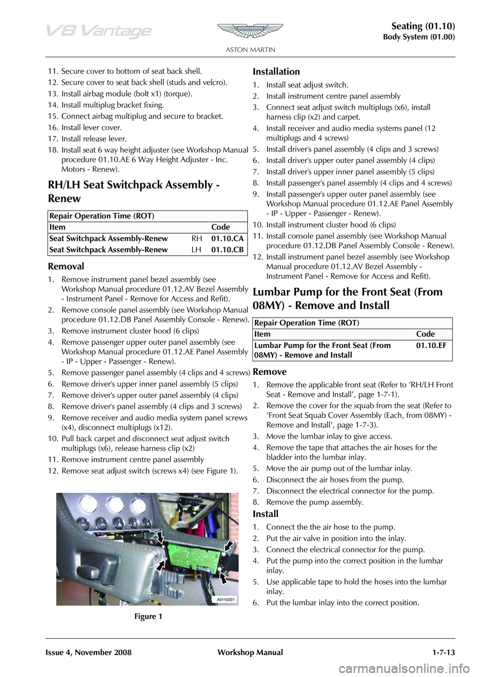
12. Remove seat adjust switch (screws x4) (see Figure 1).
Installation
1. Install seat adjust switch.
2. Install instrument centre panel assembly
3. Connect seat adjust switch multiplugs (x6), install
harness clip (x2) and carpet.
4. Install receiver and audio media systems panel (12 multiplugs and 4 screws)
5. Install driver's panel asse mbly (4 clips and 3 screws)
6. Install driver's upper oute r panel assembly (4 clips)
7. Install driver's upper inne r panel assembly (5 clips)
8. Install passenger's panel assembly (4 clips and 4 screws)
9. Install passenger's upper outer panel assembly (see
Workshop Manual procedure 01.12.AE Panel Assembly
- IP - Upper - Passenger - Renew).
10. Install instrument cluster hood (6 clips)
11. Install console panel assemb ly (see Workshop Manual
procedure 01.12.DB Panel Assembly Console - Renew).
12. Install instrument panel be zel assembly (see Workshop
Manual procedure 01.12.AV Bezel Assembly -
Instrument Panel - Remove for Access and Refit).
Lumbar Pump for the Front Seat (From
08MY) - Remove and Install
Remove
1. Remove the applicable front seat (Refer to ’RH/LH Front Seat - Remove and Install’, page 1-7-1).
2. Remove the cover for the squab from the seat (Refer to ’Front Seat Squab Cover Assembly (Each, from 08MY) -
Remove and Install’, page 1-7-3).
3. Move the lumbar inlay to give access.
4. Remove the tape that attaches the air hoses for the bladder into the lumbar inlay.
5. Move the air pump out of the lumbar inlay.
6. Disconnect the air hoses from the pump.
7. Disconnect the electrical connector for the pump.
8. Remove the pump assembly.
Install
1. Connect the the air hose to the pump.
2. Put the air valve in position into the inlay.
3. Connect the electrical connector for the pump.
4. Put the pump into the correct position in the lumbar inlay.
5. Use applicable tape to hold the hoses into the lumbar inlay.
6. Put the lumbar inlay into the correct position.
Repair Operation Time (ROT)
A0110231
Repair Operation Time (ROT)
Page 91 of 947
Instrument Panel (IP) (01.12)
Body System (01.00)
Issue 5, January 2010 Workshop Manual 1-9-3
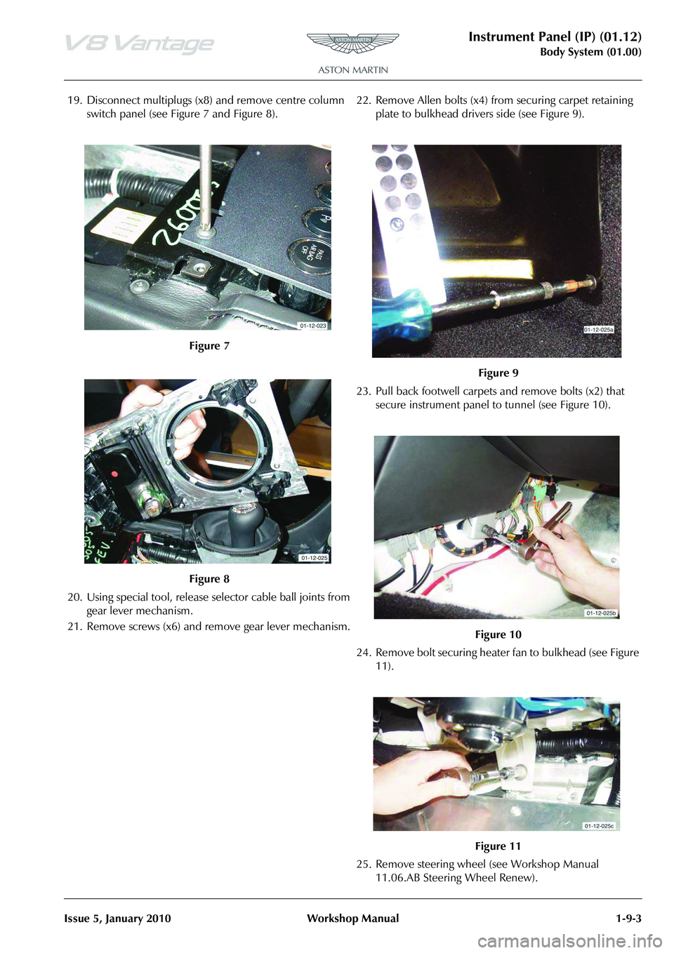
19. Disconnect multiplugs (x8) and remove centre column
switch panel (see Figure 7 and Figure 8).
20. Using special tool, release se lector cable ball joints from
gear lever mechanism.
21. Remove screws (x6) and remove gear lever mechanism. 22. Remove Allen bolts (x4) from securing carpet retaining
plate to bulkhead drivers side (see Figure 9).
23. Pull back footwell carpets and remove bolts (x2) that secure instrument panel to tunnel (see Figure 10).
24. Remove bolt securing heater fan to bulkhead (see Figure 11).
25. Remove steering wheel (see Workshop Manual 11.06.AB Steering Wheel Renew).
Figure 7
Figure 8
Figure 9
Figure 10
Figure 11
Page 93 of 947
Instrument Panel (IP) (01.12)
Body System (01.00)
Issue 5, January 2010 Workshop Manual 1-9-5
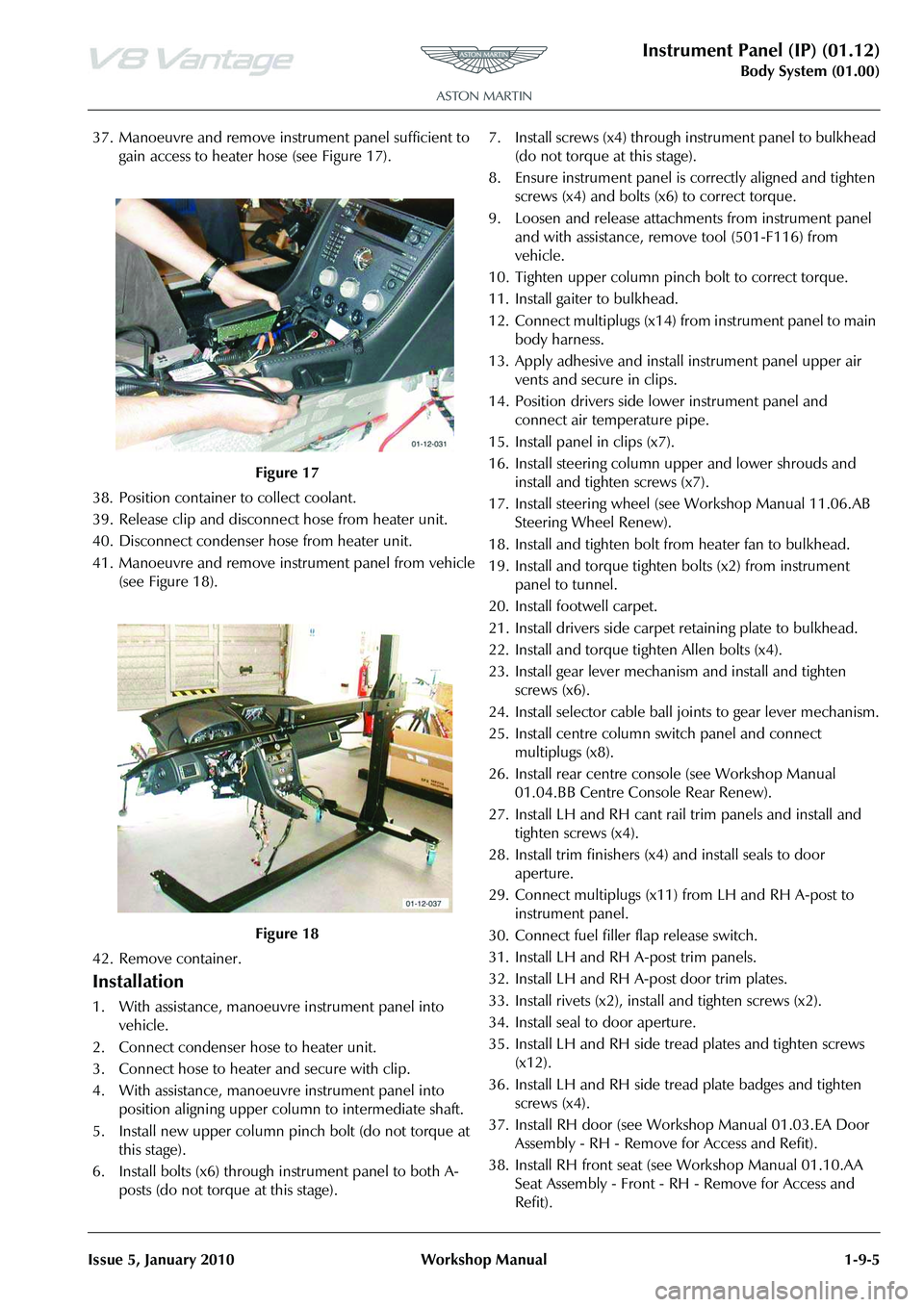
37. Manoeuvre and remove inst rument panel sufficient to
gain access to heater hose (see Figure 17).
38. Position container to collect coolant.
39. Release clip and disconne ct hose from heater unit.
40. Disconnect condenser hose from heater unit.
41. Manoeuvre and remove inst rument panel from vehicle
(see Figure 18).
42. Remove container.
Installation
1. With assistance, manoeuvre instrument panel into vehicle.
2. Connect condenser hose to heater unit.
3. Connect hose to heater and secure with clip.
4. With assistance, manoeuvre instrument panel into position aligning upper column to intermediate shaft.
5. Install new upper column pinch bolt (do not torque at this stage).
6. Install bolts (x6) through instrument panel to both A- posts (do not torque at this stage). 7. Install screws (x4) through
instrument panel to bulkhead
(do not torque at this stage).
8. Ensure instrument panel is correctly aligned and tighten screws (x4) and bolts (x6) to correct torque.
9. Loosen and release attachme nts from instrument panel
and with assistance, remove tool (501-F116) from
vehicle.
10. Tighten upper column pinch bolt to correct torque.
11. Install gaiter to bulkhead.
12. Connect multiplugs (x14) fr om instrument panel to main
body harness.
13. Apply adhesive and install instrument panel upper air
vents and secure in clips.
14. Position drivers side lower instrument panel and connect air temperature pipe.
15. Install panel in clips (x7).
16. Install steering column upper and lower shrouds and install and tighten screws (x7).
17. Install steering wheel (see Workshop Manual 11.06.AB Steering Wheel Renew).
18. Install and tighten bolt from heater fan to bulkhead.
19. Install and torque tighten bolts (x2) from instrument panel to tunnel.
20. Install footwell carpet.
21. Install drivers side carpet retaining plate to bulkhead.
22. Install and torque tighten Allen bolts (x4).
23. Install gear lever mechanism and install and tighten screws (x6).
24. Install selector cable ball joints to gear lever mechanism.
25. Install centre column switch panel and connect multiplugs (x8).
26. Install rear centre cons ole (see Workshop Manual
01.04.BB Centre Console Rear Renew).
27. Install LH and RH cant rail trim panels and install and tighten screws (x4).
28. Install trim finishers (x4) and install seals to door aperture.
29. Connect multiplugs (x11) from LH and RH A-post to
instrument panel.
30. Connect fuel filler flap release switch.
31. Install LH and RH A-post trim panels.
32. Install LH and RH A-post door trim plates.
33. Install rivets (x2), insta ll and tighten screws (x2).
34. Install seal to door aperture.
35. Install LH and RH side tread plates and tighten screws (x12).
36. Install LH and RH side tread plate badges and tighten screws (x4).
37. Install RH door (see Workshop Manual 01.03.EA Door Assembly - RH - Remove for Access and Refit).
38. Install RH front seat (see Workshop Manual 01.10.AA Seat Assembly - Front - RH - Remove for Access and
Refit).
Figure 17
Figure 18