radio ASTON MARTIN V8 VANTAGE 2010 Workshop Manual
[x] Cancel search | Manufacturer: ASTON MARTIN, Model Year: 2010, Model line: V8 VANTAGE, Model: ASTON MARTIN V8 VANTAGE 2010Pages: 947, PDF Size: 43.21 MB
Page 7 of 947
Safety Precautions
Issue 5, January 2010 Workshop Manual 0-0-7
Safety Precautions
All service workshops are a source of potential danger and
repair work should only be performed by technically trained
staff following procedures detailed in this manual. A safety
conscious approach to the performance of all service
procedures must be observed at all times. Statutory
requirements governing all aspects of health and safety at
work including directives for the proper use of materials and
equipment must be implemented.
The following contains a list of particular safety precautions
which should be observed; it is not intended to be
exhaustive.
Battery Disconnection
When a service manual procedure requires the vehicle
battery to be disconnected - always physically disconnect
the vehicle battery earth (Negative) lead.
Do not use the ‘Battery Disconnect Switch’.
After reconnecting the vehicle battery the following items
will have to be reset or re-learnt:
•Radio pre-sets
•Windows
• DTCs will be lost
Air Conditioning (A/C) System
Do not break into the A/C refrigeration system until the
refrigerant has been evacuated using the procedure detailed
in this manual. Do not disconne ct any A/C refrigerant system
pipes unless trained and instructed to do so. The refrigerant
used can cause blindness if allowed to contact your eyes.
Chemical Handling and Storage
Chemicals used in the servicing of motor vehicles include
acids, adhesives, antifreeze, brake fluids, coolants, grease,
oil, paint, resin and solvents. Exposure to certain chemicals
through direct contact or inhalation can be fatal.
Potential hazards may also be present through the incorrect
use, storage and handling of chemicals causing a fire risk.
The following precaution s should be observed.
• Strictly adhere to handling and safety information found on containers and labels.
• Do not store chemicals in unlabelled or incorrectly labelled containers.
• Containers used for storing chemicals should not be left open; there is a risk of spilling , or evaporation of fumes
which may be inflammable or toxic.
• Do not mix chemicals unless instructed to do so following manufacturers guidelines.
• Do not inhale chemical materials to determine identity, they may be toxic.
• Do not use petrol, kerosene, diesel fuel, gas oil, thinners or solvents for washing skin.
• Containers whose capacity is over 25 litres (5 gallons) require a bund wall in order to contain spillages. • Chemicals based on solvents such as paint should not be
sprayed in a confined space; work areas used for such
operations should be well ve ntilated and fume extraction
equipment should be utilised.
• Ensure that adequate ventilation is provided when volatile de-greasing agents are being used.
• Avoid splashing the skin, eyes and clothing .
• Clean chemicals from the skin and clothing as soon as
possible after soiling .
• Wear protective clothing such as goggles, non porous gloves and apron when handling battery acid and other
corrosive and toxic substances.
Electrical Equipment
• Ensure that electrical equipment is in safe working order before use.
• Inspect power leads of all mains electrical equipment for damage and security, and check that it is properly earthed.
• Ensure that electrical equipment is protected by a fuse of the correct current rating .
• Disconnect the battery before commencing repair operations to the electrical sy stem, fuel system and engine
or when working beneath the vehicle.
Exhaust Fumes
Engines should not be run in confined spaces as exhaust
fumes contain harmful and to xic substances including
carbon monoxide which can prove fatal if inhaled. Engines
must only be run where there is fume extraction equipment
in operation or where there is adequate ventilation.
Fire Precautions
• Ensure that a suitable form of fire extinguisher is conveniently located near the work area.
• Keep oils, solvents and combustible materials away from naked flames and other sources of ignition.
• Ensure that NO SMOKING signs are posted around areas where combustible materials and vapour may be present
and ensure that the warnings are strictly observed.
• Ensure that dry sand is availabl e to soak up any spillage of
fuel or other flammable solutions.
• Fume extraction equipment must be available and in full working order to remove combustible and toxic vapours.
• All personnel should be aware of the fire drill procedures and precautions. WAR NI NG
DO NOT SMOKE IN THE VICINITY OF VOLATILE DE- GREASING AGENTS.
WAR NI NG
FUME EXTRACTION EQUIPMENT MUST BE IN
OPERATION WHEN SOLVENTS ARE USED E.G. TRICHLOROETHANE, WHITE SPIRIT, SBP3,
METHYLENE CHLORIDE, PERCHLORETHYLENE.
Page 121 of 947
Handles and Lock Mechanisms (01.14)
Body System (01.00)
May 2007 Workshop Manual 1-10-1
Body System (01.00)
Handles and Lock Mechanisms (01.14)
Description
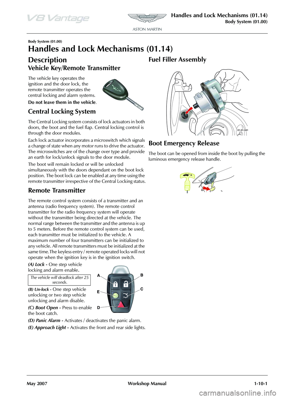
The vehicle key operates the
ignition and the door lock, the
remote transmitter operates the
central locking and alarm systems.
Do not leave them in the vehicle .
Central Locking System
The Central Locking system consists of lock actuators in both
doors, the boot and the fuel flap. Central locking control is
through the door modules.
Each lock actuator incorporates a microswitch which signals
a change of state when any motor runs to drive the actuator.
The microswitches are of the change over type and provide
an earth for lock/unlock signals to the door module.
The boot will remain locked or will be unlocked
simultaneously with the doors dependant on the boot lock
position. The boot lock can be enabled at any time using the
remote transmitter irrespective of the Central Locking status.
Remote Transmitter
The remote control system consists of a transmitter and an
antenna (radio frequency system). The remote control
transmitter for the radio frequency system will operate
without the transmitter being directed at the vehicle. The
normal range between the transmitter and the antenna is up
to 5 meters. Before the remote control system can be used,
each transmitter must be initialized to the vehicle. A
maximum number of four transmitters can be initialized to
any vehicle. All remote transmitters must be initialized at the
same time.The keyless entry / remote operated locks will not
operate when the ignition key is in the ignition switch.
(A) Lock - One step vehicle
locking and alarm enable
.
(B) Un-lock - One step vehicle
unlocking or two step vehicle
unlocking and alarm disable.
(C) Boot Open - Press to enable
the boot catch.
(D) Panic Alarm - Activates / deactivates the panic alarm.
(E) Approach Light - Activates the front and rear side lights.
Fuel Filler Assembly
Boot Emergency Release
The boot can be opened from in side the boot by pulling the
luminous emergency release handle.
The vehicle will deadlock after 25 seconds.
Page 657 of 947
Battery System (14.01)
Power Supply (14.00)14-1-2 Workshop Manual May 2007
Power Supply (14.00)
Battery System (14.01)
Description
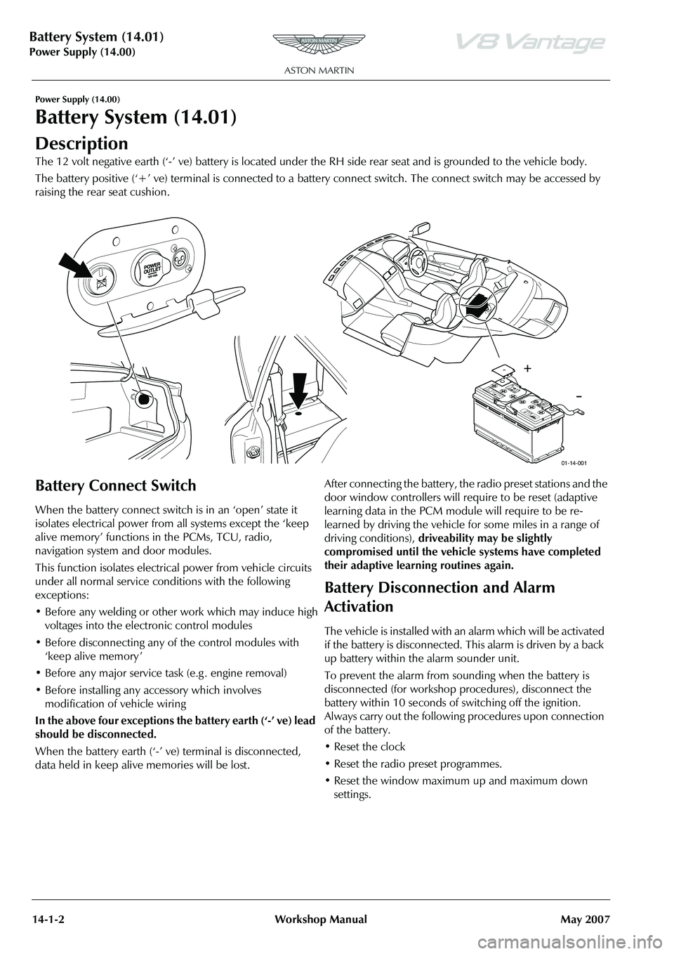
The 12 volt negative earth (‘-’ ve) battery is located under the RH side rear seat and is grounded to the vehicle body.
The battery positive (‘+’ ve) terminal is connected to a battery connect switch. The connect switch may be accessed by
raising the rear seat cushion.
Battery Connect Switch
When the battery connect switch is in an ‘open’ state it
isolates electrical power from all systems except the ‘keep
alive memory’ functions in the PCMs, TCU, radio,
navigation system and door modules.
This function isolates electri cal power from vehicle circuits
under all normal service conditions with the following
exceptions:
• Before any welding or other work which may induce high voltages into the electronic control modules
• Before disconnecting any of the control modules with ‘keep alive memory ’
• Before any major service task (e.g . engine removal)
• Before installing any accessory which involves modification of vehicle wiring
In the above four exceptions the battery earth (‘-’ ve) lead
should be disconnected.
When the battery earth (‘-’ ve) terminal is disconnected,
data held in keep alive memories will be lost. After connecting the battery, the radio preset stations and the
door window controllers will require to be reset (adaptive
learning data in the PCM module will require to be re-
learned by driving the vehicle for some miles in a range of
driving conditions),
driveability may be slightly
compromised until the vehicle systems have completed
their adaptive learning routines again.
Battery Disconnection and Alarm
Activation
The vehicle is installed with an alarm which will be activated
if the battery is disconnected. This alarm is driven by a back
up battery within the alarm sounder unit.
To prevent the alarm from so unding when the battery is
disconnected (for workshop procedures), disconnect the
battery within 10 seconds of switching off the ignition.
Always carry out the following procedures upon connection
of the battery.
• Reset the clock
• Reset the radio preset programmes.
• Reset the window maximum up and maximum down settings.
Pb
A
ST O
N
M A
R
TI
N
S H I
E L
D
E YE
S
NO S
U L
F U R
IC
A C I
DF
LU
SH
E
YES
I M
MED IA T
E LY
W IT
H
W A
T
E R
G ET
M ED
IC
AL
H ELP
F A
STSPA
R
KS
F LA
M
ES
S M
OKIN
GD AN G ER / P
OIS
ONEXP L
O S
IV E
G ASE
SC AN
C A
U SE C
A
N C A
U SE
B L
IN DN
ESS
O R
S E
V ER E
B U RNS
B
LI
NDN
ES S
O R
IN JU R
YK EEP
O UT
O F T
HE R
EA C
H O F C H
IL DR
EN D O N
OT
TI P: K EEP
V E
N T C A
PS
T IG HT
A N D L E
VE L!
1
2 V
1
2 V 9
0A
h
9
0A
h
M IN S
M
IN S
( S
AE
)
(
S
AE
)RC
RC6
80 A
M
PS
6
80 A
M
PS2R
83-1
065 5-A
A
2
R
83-1
065 5-A
A170
1 70
01-14-001
Page 812 of 947

Electronics Training Programme
INTRODUCTION
The Bluetooth system offers the following features:
• Seamless, wireless handsfree audio through a Bluetooth connection
• Digital audio interface with high qu ality, full-duplex, handsfree speech
• Speaker Independent Voice Recognition (VR)
• Voice-driven menu prompts
• Automatically mutes the radio
• Automatically pauses the CD player during calls
• Noise reduction and acoustic echo cancellation
• Compliance with Bluetooth Ha nds Free 0.96 and 1.0 profiles
• Audio through the door speakers
The Bluetooth system is standard fitment on DB9 an d is optional on the V8 Vantage. The control and
operation of the Bluetooth system is identical on a ll models, however the electrical architecture of the
cars audio does differ. To identify if Bluetooth is fitted, look for the LED Indicator located as shown
below:
LED Indicator
7
Page 822 of 947
Electronics Training Programme
OUTPUTS
V8 Vantage Outputs To Amplifier
The Bluetooth module in the V8 Vantage has three outputs sent directly to t he audio amplifier. These
outputs are:
1. Radio mute.
2. Speaker +
3. Speaker –
DB9 Outputs To Amplifier
As with the Bluetooth module in the V8 Vantage, the DB9 Bluetooth module has three outputs it
sends directly to the audio amplifie r. It should be remembered that all DB9’s feature a Linn amplifier
and therefore the Bluetooth output requir ements are different. These outputs are:
1. Radio mute.
2. Lineout -
3. Lineout +
The combination of these three signals allows the Linn Amplifier to control the audio output and
phone output through all or some of the speakers.
LED Indicator Outputs
The DB9 and V8 Vantage use the same LED Indicator (Bluetooth display) controlled in the same way
by the Bluetooth module. The output s from the Bluetooth module are:
• UIM LED - For Active Call LED (amber)
• UIM LED - For Active Call LED (blue)
These two outputs individually control the status LED’s (amber and blue) earth signal therefore
switching the LED’s on and off independently.
17
Page 836 of 947
Electronics Training Programme
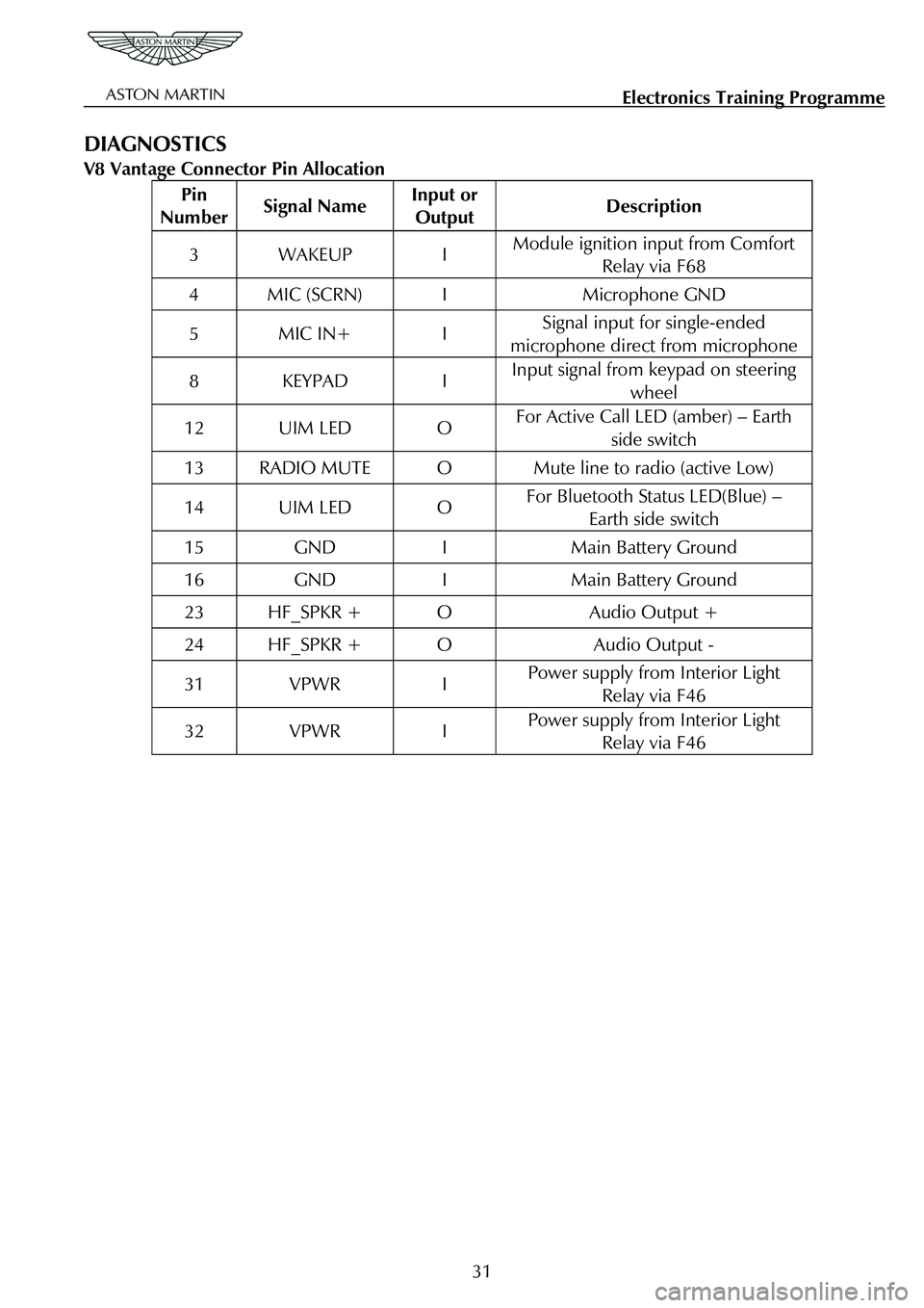
DIAGNOSTICS
V8 Vantage Connector Pin Allocation
Pin
Number Signal Name Input or
Output Description
3 WAKEUP I Module ignition input from Comfort
Relay via F68
4 MIC (SCRN) I Microphone GND
5 MIC IN+ I Signal input for single-ended
microphone direct from microphone
8 KEYPAD I Input signal from keypad on steering wheel
12 UIM LED O For Active Call LED (amber) – Earth
side switch
13 RADIO MUTE O Mute line to radio (active Low)
14 UIM LED O For Bluetooth Status LED(Blue) – Earth side switch
15 GND I Main Battery Ground
16 GND I Main Battery Ground
23 HF_SPKR + O Audio Output +
24 HF_SPKR + O Audio Output -
31 VPWR I Power supply from Interior Light Relay via F46
32 VPWR I Power supply from Interior Light Relay via F46
31
Page 837 of 947
Electronics Training Programme
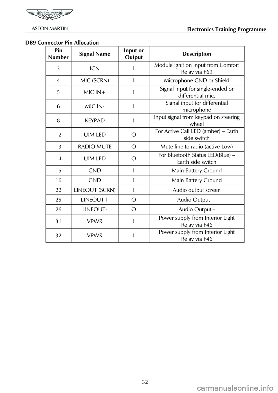
DB9 Connector Pin Allocation
Pin
Number Signal Name Input or
Output Description
3 IGN I Module ignition input from Comfort
Relay via F69
4 MIC (SCRN) I Microphone GND or Shield
5 MIC IN+ I Signal input for single-ended or
differential mic.
6 MIC IN- I Signal input for differential microphone
8 KEYPAD I Input signal from keypad on steering
wheel
12 UIM LED O For Active Call LED (amber) – Earth side switch
13 RADIO MUTE O Mute line to radio (active Low)
14 UIM LED O For Bluetooth Status LED(Blue) – Earth side switch
15 GND I Main Battery Ground
16 GND I Main Battery Ground
22 LINEOUT (SCRN) I Audio output screen
25 LINEOUT+ O Audio Output +
26 LINEOUT- O Audio Output -
31 VPWR I Power supply from Interior Light Relay via F46
32 VPWR I Power supply from Interior Light Relay via F46
32