run flat ASTON MARTIN V8 VANTAGE 2010 Workshop Manual
[x] Cancel search | Manufacturer: ASTON MARTIN, Model Year: 2010, Model line: V8 VANTAGE, Model: ASTON MARTIN V8 VANTAGE 2010Pages: 947, PDF Size: 43.21 MB
Page 10 of 947

Vehicle Recovery
0-0-10 Workshop Manual Issue 5, January 2010
Vehicle Recovery
General
Preferred method of vehicle recovery is by flat bed
transporter.
The towing eye is primarily for emergency use when towing
for short distances, e.g. removing vehicle if it is causing an
obstruction or winching vehicl e onto a flatbed transporter.
If moving this vehicle in such a situation, install the towing
eye to the bracket in the lower grille aperture.
Transporting
If vehicle is to be transported on a trailer or flat bed
transporter the handbrake must be applied and the road
wheels must be chocked.
Suspended Towing
Take care when using 'spectacle frame' type towing
equipment that the towing device is well clear of front or
rear apron. Body damage may occur if vehicle passes over
uneven road surfaces.
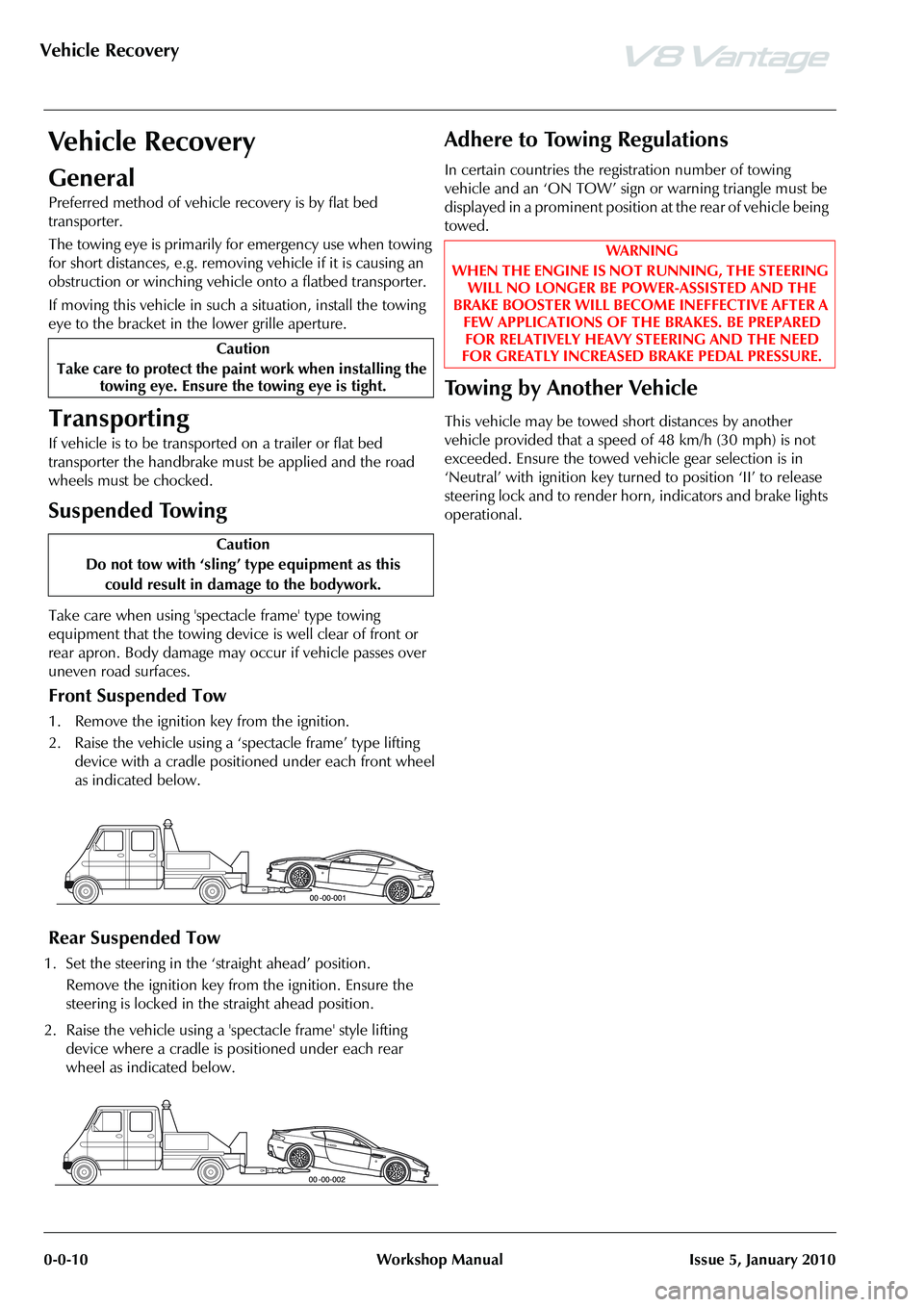
Front Suspended Tow
1. Remove the ignition key from the ignition.
2. Raise the vehicle using a ‘spectacle frame’ type lifting device with a cradle positioned under each front wheel
as indicated below.
Rear Suspended Tow
1. Set the steering in the ‘straight ahead’ position.
Remove the ignition key from the ignition. Ensure the
steering is locked in the straight ahead position.
2. Raise the vehicle using a 'spectacle frame' style lifting device where a cradle is positioned under each rear
wheel as indicated below.
Adhere to Towing Regulations
In certain countries the regi stration number of towing
vehicle and an ‘ON TOW’ sign or warning triangle must be
displayed in a prominent position at the rear of vehicle being
towed.
To w i n g b y A n o t h e r V e h i c l e
This vehicle may be towed short distances by another
vehicle provided that a speed of 48 km/h (30 mph) is not
exceeded. Ensure the towed vehicle gear selection is in
‘Neutral’ with ignition key turned to position ‘II’ to release
steering lock and to render hor n, indicators and brake lights
operational.
Caution
Take care to protect the paint work when installing the towing eye. Ensure the towing eye is tight.
Caution
Do not tow with ‘sling’ type equipment as this
could result in damage to the bodywork.
WAR NI NG
WHEN THE ENGINE IS NOT RUNNING, THE STEERING WILL NO LONGER BE POWER-ASSISTED AND THE
BRAKE BOOSTER WILL BECOME INEFFECTIVE AFTER A FEW APPLICATIONS OF TH E BRAKES. BE PREPARED
FOR RELATIVELY HEAVY STEERING AND THE NEED
FOR GREATLY INCREASED BRAKE PEDAL PRESSURE.
Page 453 of 947

Road Wheels and Tyres (04.04)
Suspension (04.00)
May 2007 Workshop Manual 4-4-3
Maintenance
Factory installed tyres and road wheels are designed to
operate satisfactory when inflated to the recommended
inflation pressures (Refer to ’Inspection and Verification’,
page 4-4-4). The recommended pressures apply to vehicle
loads up to and including the full-rated load capacity.
Correct tyre pressures and driving technique have an
important influence on tyre life. Heavy cornering,
excessively rapid acceleration and unnecessary sharp
braking increase tyre wear.
Replacement tyres should follow the recommended:
The use of any other size or type may seriously affect:
Wheels need to be renewed when:
Safety
Tyre Replacement and Wheel
Interchanging
When replacement of tyres is required it is preferable to
install a complete vehicle set. S hould either the front or rear
tyres only show excessive wear, new tyres must be installed
to replace worn ones. Under no circumstances interchange
tyres from side to side, front to re ar or vice versa as individual
tyre wear produces unique characteristics depending upon
their position. If the position is changed after wear has
occurred, the performance of the tyre will be adversely
affected.
New tyres must be balanced before installing to the vehicle.
•Size
•Speed rating
•Load range
• Radial construction type
•Safety
•Ride
•Handling
• Speedometer and Odometer calibration • Vehicle ground clearance
• Tyre clearance between
body and chassis
• Wheel bearing life
• Brake cooling
• Impact damaged
• Heavily corroded
• Porous • Wheel stud holes or seats
become damaged
• They have excessive radial or lateral runout.
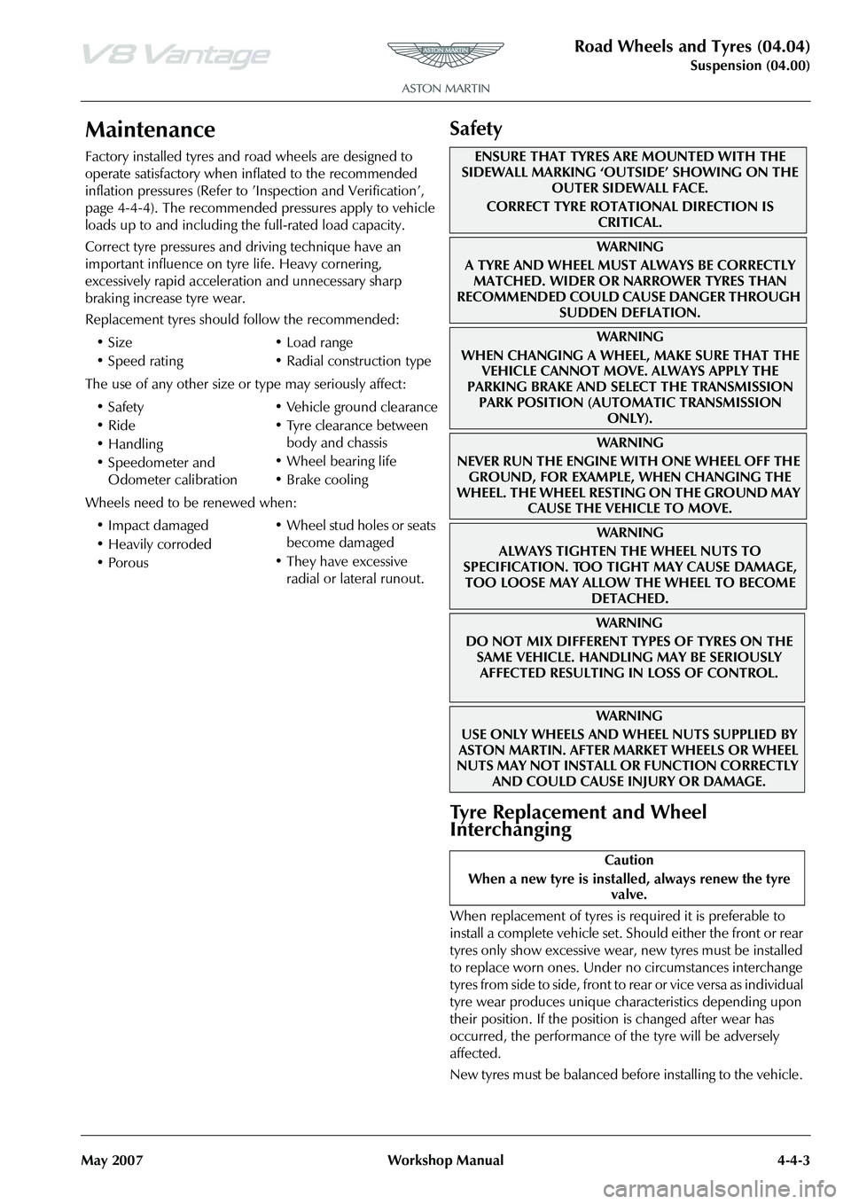
ENSURE THAT TYRES ARE MOUNTED WITH THE
SIDEWALL MARKING ‘OUTSIDE’ SHOWING ON THE
OUTER SIDEWALL FACE.
CORRECT TYRE ROTATIONAL DIRECTION IS CRITICAL.
WA R N I N G
A TYRE AND WHEEL MUST ALWAYS BE CORRECTLY MATCHED. WIDER OR NARROWER TYRES THAN
RECOMMENDED COULD CAUSE DANGER THROUGH
SUDDEN DEFLATION.
WA R N I N G
WHEN CHANGING A WHEEL, MAKE SURE THAT THE VEHICLE CANNOT MOVE. ALWAYS APPLY THE
PARKING BRAKE AND SELE CT THE TRANSMISSION
PARK POSITION (AUTOMATIC TRANSMISSION ONLY).
WA R N I N G
NEVER RUN THE ENGINE WITH ONE WHEEL OFF THE GROUND, FOR EXAMPLE, WHEN CHANGING THE
WHEEL. THE WHEEL RESTING ON THE GROUND MAY CAUSE THE VEHICLE TO MOVE.
WA R N I N G
ALWAYS TIGHTEN THE WHEEL NUTS TO
SPECIFICATION. TOO TIGHT MAY CAUSE DAMAGE,
TOO LOOSE MAY ALLOW TH E WHEEL TO BECOME
DETACHED.
WAR NI NG
DO NOT MIX DIFFERENT TY PES OF TYRES ON THE
SAME VEHICLE. HANDLING MAY BE SERIOUSLY AFFECTED RESULTING IN LOSS OF CONTROL.
WAR NI NG
USE ONLY WHEELS AND WHEEL NUTS SUPPLIED BY
ASTON MARTIN. AFTER MARKET WHEELS OR WHEEL
NUTS MAY NOT INSTALL OR FUNCTION CORRECTLY
AND COULD CAUSE INJURY OR DAMAGE.
Caution
When a new tyre is installe d, always renew the tyre
valve.
Page 455 of 947

Road Wheels and Tyres (04.04)
Suspension (04.00)
May 2007 Workshop Manual 4-4-5
Road Test
A tyre vibration diagnostic proc edure always begins with a road test. The road test and customer interview (if available)
will provide much of the information neede d to find the source of a vibration.
During the road test, drive the vehicle on a road that is smoot h and free of undulations. If vibration is apparent, note and
record the following:
• The speed at which the vibration occurs
• What type of vibration occurs in each speed range
• How the vibration is affected by changes in the following types of vibration-sensitivity:
Torque Sensitive - This means that the condition may be improved or made worse by accelerating, decelerating, coasting,
maintaining a steady vehicle speed or applying engine torque.
Vehicle Speed Sensitive - This means that the vibration always occurs at the same vehicle speed and is not affected by
engine torque, engine speed or the transmission gear selected.
Engine Speed Sensitive - This means that the vibration occurs at varyin g vehicle speeds when a different transmission
gear is selected. It may sometimes be isolated by increasing or decreasing engine speed with the transmission in NEUTRAL
or by stall testing with the transmission in gear. If the condition is engine speed sensitive, the cause is probably not relate d
to the tyres.
If the road test indicates that there is tyre whine, but no sh ake or vibration, the noise originates with the contact between
the tyre and the road surface.
A thumping noise usually means that the tyre has a flat or soft spot making a noise as they slap the roadway. Tyre whine
may be distinguished from axle noise. Tyre whine remains the same over a range of speeds.
Symptoms
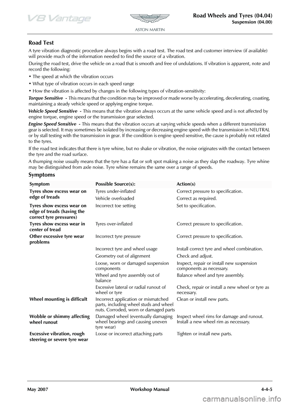
SymptomPossible Source(s):Action(s)
Tyres show excess wear on
edge of treads Tyres under-inflated Correct pressure to specification.
Vehicle overloaded Correct as required.
Tyres show excess wear on
edge of treads (having the
correct tyre pressures) Incorrect toe setting Set to specification.
Tyres show excess wear in
center of tread Tyres over-inflated Correct pressure to specification.
Other excessive tyre wear
problems Incorrect tyre pressure Correct pressure to specification.
Incorrect tyre and wheel usage Install correct tyre and wheel combination.
Geometry out of alignm
ent Check and adjust.
Loose, worn or damaged suspension
components Inspect, repair or install new suspension
components as necessary.
Wheel and tyre assembly out of
balance Balance wheel and tyre assembly.
Excessive lateral or radial runout of
wheel or tyre Check, repair or install a new wheel or tyre as
necessary.
Wheel mounting is difficult Incorrect application or mismatched
parts, including wheel studs and wheel
nuts. Corroded, worn or damaged parts Clean or install new parts.
Wobble or shimmy affecting
wheel runout Damaged wheel (eventually damaging
wheel bearings and causing uneven
tyre wear) Inspect wheel rims for damage and runout.
Install a new wheel rim as necessary.
Excessive vibration, rough
steering or severe tyre wear Loose or incorrect attaching parts Tighten or install new parts.
Page 456 of 947

Road Wheels and Tyres (04.04)
Suspension (04.00)4-4-6 Workshop Manual May 2007
Ty r e D a m a g e
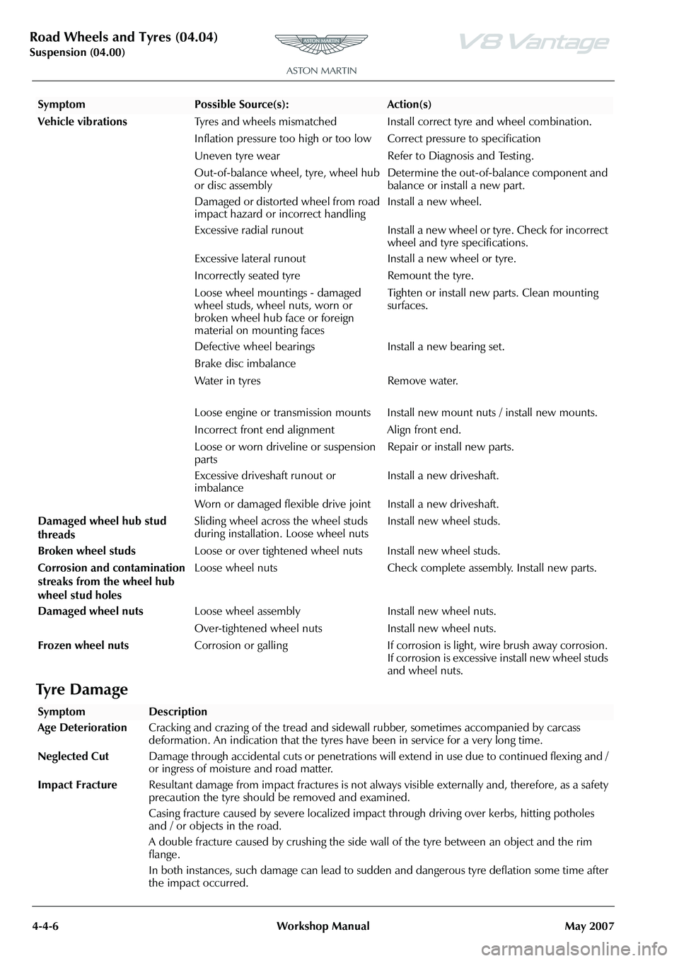
Vehicle vibrations Tyres and wheels mismatched Install correct tyre and wheel combination.
Inflation pressure too high or too lo w Correct pressure to specification
Uneven tyre wear Refer to Diagnosis and Testing .
Out-of-balance wheel, tyre, wheel hub
or disc assembly Determine the out-of-balance component and
balance or install a new part.
Damaged or distorted wheel from road
impact hazard or incorrect handling Install a new wheel.
Excessive radial runout Install a new wheel or tyre. Check for incorrect wheel and tyre specifications.
Excessive lateral runout Install a new wheel or tyre.
Incorrectly seated tyre Remount the tyre.
Loose wheel mountings - damaged
wheel studs, wheel nuts, worn or
broken wheel hub face or foreign
material on mounting faces Tighten or install new parts. Clean mounting
surfaces.
Defective wheel bearings Install a new bearing set.
Brake disc imbalance
Water in tyres Remove water.
Loose engine or transmission mounts Install new mount nuts / install new mounts.
Incorrect front end alignment Align front end.
Loose or worn driveline or suspension
parts Repair or install new parts.
Excessive driveshaft runout or
imbalance Install a new driveshaft.
Worn or damaged flexible drive joint Install a new driveshaft.
Damaged wheel hub stud
threads Sliding wheel across the wheel studs
during installation. Loose wheel nuts
Install new wheel studs.
Broken wheel studs Loose or over tightened wheel nuts Install new wheel studs.
Corrosion and contamination
streaks from the wheel hub
wheel stud holes Loose wheel nuts Check complete assembly. Install new parts.
Damaged wheel nuts Loose wheel assembly Install new wheel nuts.
Over-tightened wheel nuts Install new wheel nuts.
Frozen wheel nuts Corrosion or galling If corrosion is light, wire brush away corrosion.
If corrosion is excessive install new wheel studs
and wheel nuts.
SymptomPossible Source(s):Action(s)
SymptomDescription
Age Deterioration Cracking and crazing of the tread and side wall rubber, sometimes accompanied by carcass
deformation. An indication that the tyres have been in service for a very long time.
Neglected Cut Damage through accidental cuts or penetrations will extend in use due to continued flexing and /
or ingress of moisture and road matter.
Impact Fracture Resultant damage from impact fractures is not always visible externally and, therefore, as a safety
precaution the tyre should be removed and examined.
Casing fracture caused by severe localized impact through driving over kerbs, hitting potholes
and / or objects in the road.
A double fracture caused by crushing the side wall of the tyre between an object and the rim
flange.
In both instances, such damage can lead to sudd en and dangerous tyre deflation some time after
the impact occurred.