wheel size ASTON MARTIN V8 VANTAGE 2010 Workshop Manual
[x] Cancel search | Manufacturer: ASTON MARTIN, Model Year: 2010, Model line: V8 VANTAGE, Model: ASTON MARTIN V8 VANTAGE 2010Pages: 947, PDF Size: 43.21 MB
Page 453 of 947
Road Wheels and Tyres (04.04)
Suspension (04.00)
May 2007 Workshop Manual 4-4-3
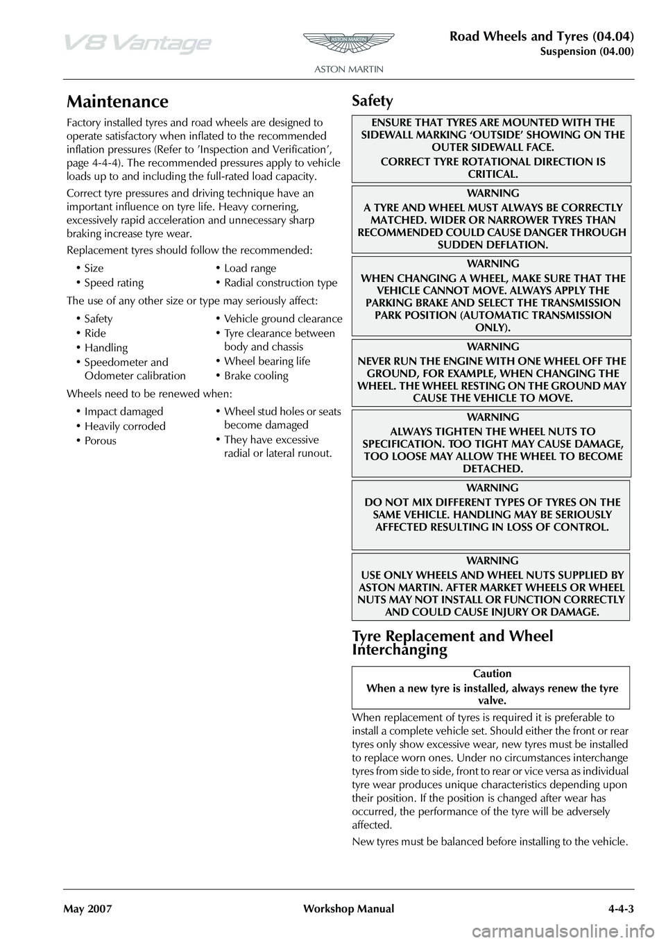
Maintenance
Factory installed tyres and road wheels are designed to
operate satisfactory when inflated to the recommended
inflation pressures (Refer to ’Inspection and Verification’,
page 4-4-4). The recommended pressures apply to vehicle
loads up to and including the full-rated load capacity.
Correct tyre pressures and driving technique have an
important influence on tyre life. Heavy cornering,
excessively rapid acceleration and unnecessary sharp
braking increase tyre wear.
Replacement tyres should follow the recommended:
The use of any other size or type may seriously affect:
Wheels need to be renewed when:
Safety
Tyre Replacement and Wheel
Interchanging
When replacement of tyres is required it is preferable to
install a complete vehicle set. S hould either the front or rear
tyres only show excessive wear, new tyres must be installed
to replace worn ones. Under no circumstances interchange
tyres from side to side, front to re ar or vice versa as individual
tyre wear produces unique characteristics depending upon
their position. If the position is changed after wear has
occurred, the performance of the tyre will be adversely
affected.
New tyres must be balanced before installing to the vehicle.
•Size
•Speed rating
•Load range
• Radial construction type
•Safety
•Ride
•Handling
• Speedometer and Odometer calibration • Vehicle ground clearance
• Tyre clearance between
body and chassis
• Wheel bearing life
• Brake cooling
• Impact damaged
• Heavily corroded
• Porous • Wheel stud holes or seats
become damaged
• They have excessive radial or lateral runout.
ENSURE THAT TYRES ARE MOUNTED WITH THE
SIDEWALL MARKING ‘OUTSIDE’ SHOWING ON THE
OUTER SIDEWALL FACE.
CORRECT TYRE ROTATIONAL DIRECTION IS CRITICAL.
WA R N I N G
A TYRE AND WHEEL MUST ALWAYS BE CORRECTLY MATCHED. WIDER OR NARROWER TYRES THAN
RECOMMENDED COULD CAUSE DANGER THROUGH
SUDDEN DEFLATION.
WA R N I N G
WHEN CHANGING A WHEEL, MAKE SURE THAT THE VEHICLE CANNOT MOVE. ALWAYS APPLY THE
PARKING BRAKE AND SELE CT THE TRANSMISSION
PARK POSITION (AUTOMATIC TRANSMISSION ONLY).
WA R N I N G
NEVER RUN THE ENGINE WITH ONE WHEEL OFF THE GROUND, FOR EXAMPLE, WHEN CHANGING THE
WHEEL. THE WHEEL RESTING ON THE GROUND MAY CAUSE THE VEHICLE TO MOVE.
WA R N I N G
ALWAYS TIGHTEN THE WHEEL NUTS TO
SPECIFICATION. TOO TIGHT MAY CAUSE DAMAGE,
TOO LOOSE MAY ALLOW TH E WHEEL TO BECOME
DETACHED.
WAR NI NG
DO NOT MIX DIFFERENT TY PES OF TYRES ON THE
SAME VEHICLE. HANDLING MAY BE SERIOUSLY AFFECTED RESULTING IN LOSS OF CONTROL.
WAR NI NG
USE ONLY WHEELS AND WHEEL NUTS SUPPLIED BY
ASTON MARTIN. AFTER MARKET WHEELS OR WHEEL
NUTS MAY NOT INSTALL OR FUNCTION CORRECTLY
AND COULD CAUSE INJURY OR DAMAGE.
Caution
When a new tyre is installe d, always renew the tyre
valve.
Page 461 of 947
Road Wheels and Tyres (04.04)
Suspension (04.00)
May 2007 Workshop Manual 4-4-11
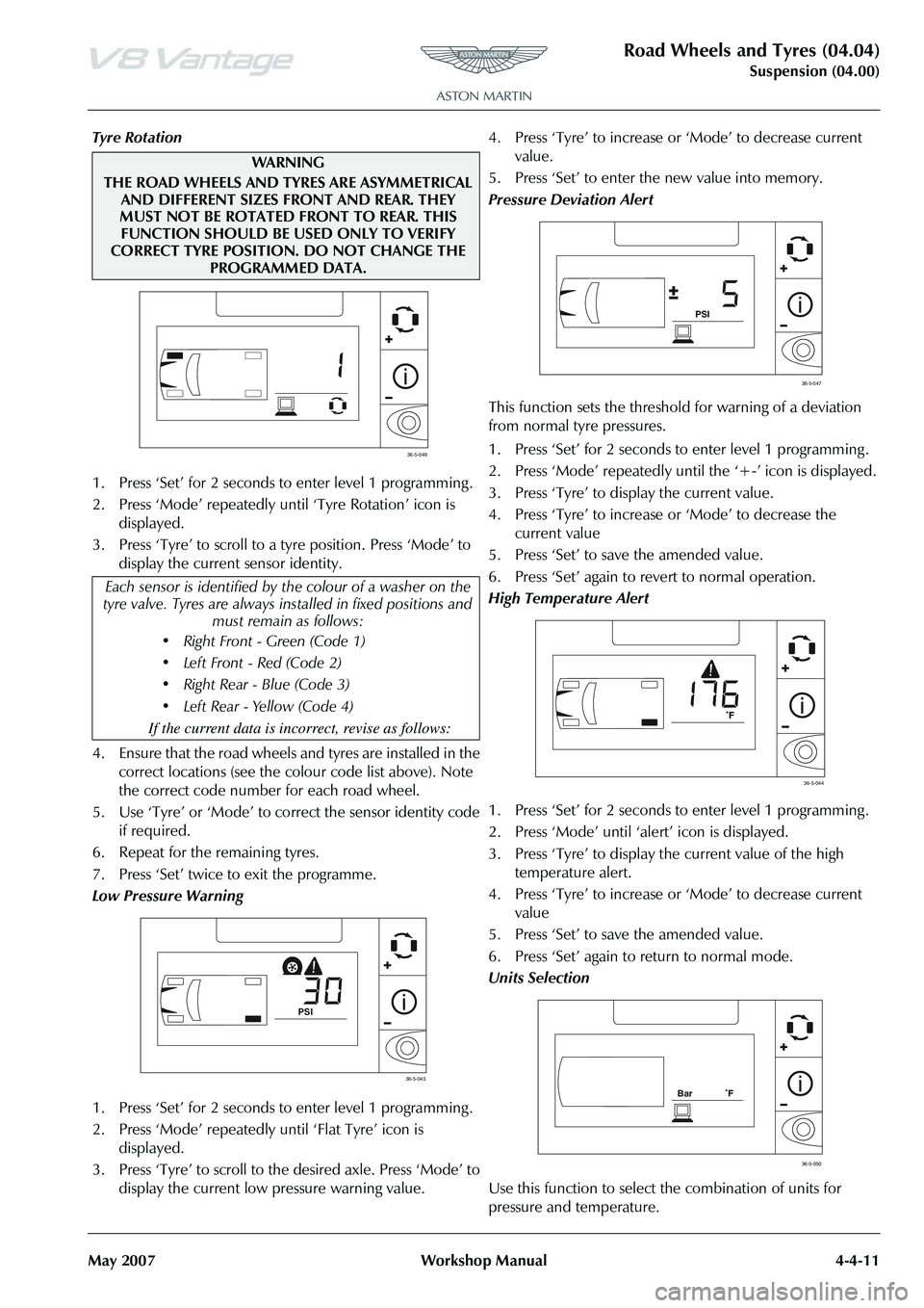
Tyre Rotation
1. Press ‘Set’ for 2 seconds to enter level 1 programming .
2. Press ‘Mode’ repeatedly until ‘Tyre Rotation’ icon is displayed.
3. Press ‘Tyre’ to scroll to a tyre position. Press ‘Mode’ to display the current sensor identity.
4. Ensure that the road wheels and tyres are installed in the correct locations (see the colour code list above). Note
the correct code number for each road wheel.
5. Use ‘Tyre’ or ‘Mode’ to co rrect the sensor identity code
if required.
6. Repeat for the remaining tyres.
7. Press ‘Set’ twice to exit the programme.
Low Pressure Warning
1. Press ‘Set’ for 2 seconds to enter level 1 programming .
2. Press ‘Mode’ repeatedly until ‘Flat Tyre’ icon is displayed.
3. Press ‘Tyre’ to scroll to th e desired axle. Press ‘Mode’ to
display the current low pressure warning value. 4. Press ‘Tyre’ to increase or
‘Mode’ to decrease current
value.
5. Press ‘Set’ to enter the new value into memory.
Pressure Deviation Alert
This function sets the threshold for warning of a deviation
from normal tyre pressures.
1. Press ‘Set’ for 2 seconds to enter level 1 programming .
2. Press ‘Mode’ repeatedly until the ‘+-’ icon is displayed.
3. Press ‘Tyre’ to display the current value.
4. Press ‘Tyre’ to increase or ‘Mode’ to decrease the
current value
5. Press ‘Set’ to save the amended value.
6. Press ‘Set’ again to revert to normal operation.
High Temperature Alert
1. Press ‘Set’ for 2 seconds to enter level 1 programming .
2. Press ‘Mode’ until ‘ale rt’ icon is displayed.
3. Press ‘Tyre’ to display the current value of the high temperature alert.
4. Press ‘Tyre’ to increase or ‘Mode’ to decrease current
value
5. Press ‘Set’ to save the amended value.
6. Press ‘Set’ again to return to normal mode.
Units Selection
Use this function to select the combination of units for
pressure and temperature.
WAR NI N G
THE ROAD WHEELS AND TYRES ARE ASYMMETRICAL AND DIFFERENT SIZES FRONT AND REAR. THEY
MUST NOT BE ROTATED FRONT TO REAR. THIS FUNCTION SHOULD BE USED ONLY TO VERIFY
CORRECT TYRE POSITION. DO NOT CHANGE THE PROGRAMMED DATA.
Each sensor is identified by th e colour of a washer on the
tyre valve. Tyres are always in stalled in fixed positions and
must remain as follows:
• Right Front - Green (Code 1)
• Left Front - Red (Code 2)
Page 601 of 947
Steering Gear (11.01)
Steering (11.00)11-1-2 Workshop Manual Issue 5, January 2010
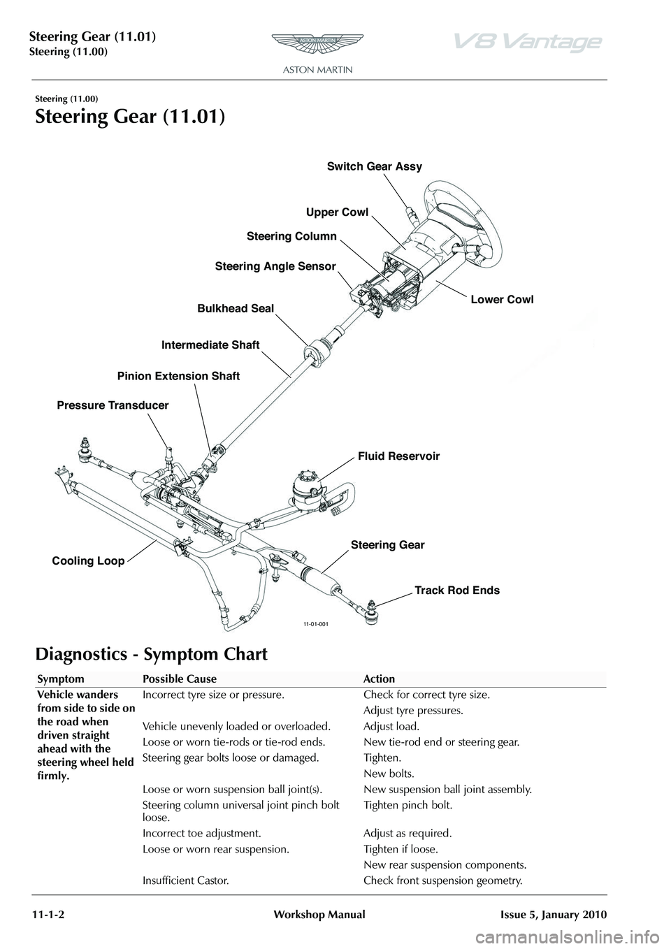
Steering (11.00)
Steering Gear (11.01)
Diagnostics - Symptom Chart
11-01-001
Upper Cowl Lower Cowl
Steering Column
Steering Angle Sensor
Bulkhead Seal
Intermediate Shaft
Pressure Transducer Pinion Extension Shaft
Cooling Loop Switch Gear Assy
Fluid Reservoir
Steering Gear Track Rod Ends
SymptomPossible CauseAction
Vehicle wanders
from side to side on
the road when
driven straight
ahead with the
steering wheel held
firmly. Incorrect tyre size or pressure. Check for correct tyre size.
Adjust tyre pressures.
Vehicle unevenly loaded or overloaded. Adjust load.
Loose or worn tie-rods or tie-rod ends. New tie-rod end or steering gear.
Steering gear bolts loose or damaged. Tighten. New bolts.
Loose or worn suspension ball joint(s). New suspension ball joint assembly.
Steering column universal joint pinch bolt
loose. Tighten pinch bolt.
Incorrect toe adjustment. Adjust as required.
Loose or worn rear suspension. Tighten if loose. New rear suspension components.
Insufficient Castor. Check fr ont suspension geometry.
Page 602 of 947
Steering Gear (11.01)
Steering (11.00)
Issue 5, January 2010 Workshop Manual 11-1-3
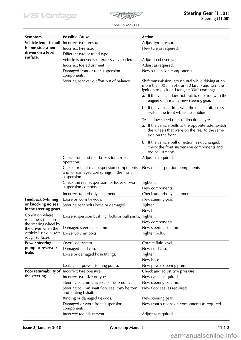
Vehicle tends to pull
to one side when
driven on a level
surface. Incorrect tyre pressure. Adjust tyre pressure.
Incorrect tyre size.
Different tyre or tread type.
New tyre as required.
Vehicle is unevenly or excessively loaded. Adjust load evenly.
Incorrect toe adjustment. Adjust as required.
Damaged front or rear suspension
components. New suspension components.
Steering gear valve effort out of balance. Shift transmission into neutral while driving at no more than 30 miles/hour (50 km/h) and turn the
ignition to position I (engine ‘Off’-coasting).
a. If the vehicle does not pull to one side with the
engine off, install a new steering gear.
b. If the vehicle drifts with the engine off, ‘cross switch’ the front wheel assemblies.
Test at low speed due to directional tyres.
a. If the vehicle pulls to the opposite side, switch the wheels that were on the rear to the same
side on the front.
b. If the vehicle pull direction is not changed, check the front suspension components and
toe adjustments.
Check front and rear brakes for correct
operation. Adjust as required.
Check for bent rear suspension components
and for damaged coil springs in the front
suspension. New rear suspension components.
Check the rear suspension for loose or worn
suspension components. Tighten.
New components.
Incorrect underbody alignment. Check underbody alignment.
Feedback (whining
or knocking noises
in the steering gear)
Condition where
roughness is felt in
the steering wheel by
the driver when the
vehicle is driven over
rough surfaces. Loose or worn tie-rods. New steering gear.
Steering gear bolts loose or damaged. Tighten.
New bolts.
Loose suspension bushing , bolts or ball joints. Tighten.
New components.
Damaged steering column.
Loose Column bolts. New steering column.
Tighten bolts.
Power steering
pump or reservoir
leaks Overfilled system. Correct fluid level.
Damaged fluid cap. New fluid cap.
Loose or damaged hose fittings. Tighten.
New hose.
Leakage at power steering pump. New power steering pump.
Poor returnability of
the steering Incorrect tyre pressure. Check
and adjust tyre pressure.
Incorrect tyre size or ty pe. New tyre as required.
Steering column universal joints binding . New steering column.
Steering column shaft floor seal may be torn
and fouling I-shaft. New floor seal as required.
Binding or damaged tie-rods. New steering gear.
Damaged or worn front suspension
components. New front suspension components as required.
Incorrect toe adjustment. Adjust as required.
SymptomPossible CauseAction
Page 753 of 947
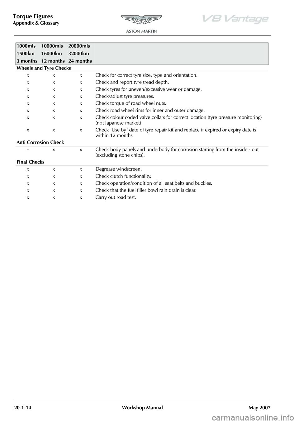
Torque Figures
Appendix & Glossary20-1-14 Workshop Manual May 2007
Wheels and Tyre Checks
x x x Check for correct tyre size, type and orientation.
x x x Check and report tyre tread depth.
x x x Check tyres for uneven/excessive wear or damage.
x x x Check/adjust tyre pressures.
x x x Check torque of road wheel nuts.
x x x Check road wheel rims for inner and outer damage.
x x x Check colour coded valve collars for co rrect location (tyre pressure monitoring)
(not Japanese market)
x x x Check ‘Use by ’ date of tyre repair kit and replace if expired or expiry date is
within 12 months
Anti Corrosion Check - x x Check body panels and underbody for corrosion starting from the inside - out
(excluding stone chips).
Final Checks x x x Degrease windscreen.
x x x Check clutch functionality.
x x x Check operation/condition of all seat belts and buckles.
x x x Check that the fuel filler bowl rain drain is clear.
x x x Carry out road test.
1000mls
1500km
3 months10000mls
16000km
12 months20000mls
32000km
24 months
Page 883 of 947
AML EOBD System Operation Summary
Rory O’Curry Aston Martin Lagonda CONFIDENTIAL 1 May 2009
[email protected] AML EOBD Monitors 07 ROC.doc Page 37 of 43
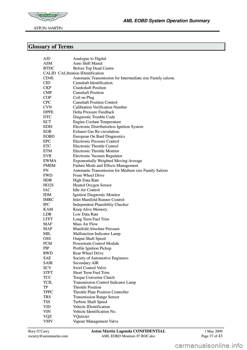
Glossary of Terms
A/D Analogue to Digital
ASM Auto Shift Manul
BTDC Before Top Dead Centre
CALID CALibration IDentification
CD4E Automatic Transmission for Intermediate size Family saloon.
CID Camshaft Identification.
CKP Crankshaft Position
CMP Camshaft Position
COP Coil on Plug
CPC Camshaft Position Control
CVN Calibration Verification Number
DPFE Delta Pressure Feedback
DTC Diagnostic Trouble Code
ECT Engine Coolant Temperature
EDIS Electronic Distributorless Ignition System
EGR Exhaust Gas Re-circulation.
EOBD European On Bard Diagnostics
EPC Electronic Pressure Control
ETC Electronic Throttle Control
ETM Electronic Throttle Monitor
EVR Electronic Vacuum Regulator
EWMA Exponentially Weighted Moving Average
FMEM Failure Mode and Effects Management
FN Automatic Transmission for Medium size Family Saloon
FWD Front Wheel Drive
HDR High Data Rate
HO2S Heated Oxygen Sensor.
IAC Idle Air Control
IDM Ignition Diagnostic Monitor
IMRC Inlet Manifold Runner Control
IPC Independent Plausibility Checker
KAM Keep Alive Memory
LDR Low Data Rate
LTFT Long Term Fuel Trim
MAF Mass Air Flow
MAP Manifold Absolute Pressure
MIL Malfunction Indicator Lamp
OSS Output Shaft Speed
PCM Powertrain Control Module
PIP Profile Ignition Pickup
RWD Rear Wheel Drive
SAE Society of Automotive Engineers
SAIR Secondary AIR
SCV Swirl Control Valve
STFT Short Term Fuel Trim
TCC Torque Converter Clutch
TCIL Transmission Control Indicator Lamp
TP Throttle Position
TPPC Throttle Plate Position Controller
TRS Transmission Range Sensor
TSS Turbine Shaft Speed
VID Vehicle IDentification
VIN Vehicle Identification No.
VQZ VQuizzer
VMV Vapour Management Valve