check oil AUDI A3 1996 8L / 1.G ATW Engine Ignition System Workshop Manual
[x] Cancel search | Manufacturer: AUDI, Model Year: 1996, Model line: A3, Model: AUDI A3 1996 8L / 1.GPages: 59, PDF Size: 0.53 MB
Page 2 of 59
28-2
Safety precautions
To reduce the risk of personal injury and/or
damage to the fuel injection and ignition system,
always observe the following:
Do not touch or disconnect ignition wires when
engine is running or turning at starting RPM.
Always switch ignition off before disconnecting
or reconnecting wires for the injection and
ignition system, including high voltage wiring
and test leads.
If engine is to be cranked at starting RPM
without starting (e.g. for compression testing),
disconnect connector from ignition coils and
from fuel injectors.
It is possible that the control module will
recognize a malfunction and store a DTC during
some tests. After completing all tests and
repairs, DTC memory should therefore be
checked and erased if necessary. Readiness
code must be generated after DTC memory is
erased Page 01
-73
.
Always switch ignition off before cleaning
engine.
Pa
ge 2 of 59 I
gnition s
ystem, checkin
g
11/21/2002 htt
p://127.0.0.1:8080/audi/servlet/Dis
play?action=Goto&t
yp
e=re
pair&id=AUDI.B5.FU06.28.1
Page 3 of 59
28-3
Technical data
Engine identification
ATW (1.8 L / 5V/ 110 kW engine)
Idle speed
Engine speed cannot be adjusted, it is
regulated by idle stabilization Front Wheel Drive (FWD): 740 to 860 RPM
All-Wheel Drive Vehicles: 800 to 920 RPM
Engine speed (RPM) limitation
Via fuel injector shut-off
about 6800 RPM
Ignition timing is determined in the control
module
It is not possible to adjust the ignition
timing
Ignition system Single coil ignition system with 4 ignition coils (power output stages integrated)
that are connected directly to spark plugs via the ignition cables.
Spark plugs Tightening torque 30 Nm.
Firing sequence 1-3-4-2
Pa
ge 3 of 59 I
gnition s
ystem, checkin
g
11/21/2002 htt
p://127.0.0.1:8080/audi/servlet/Dis
play?action=Goto&t
yp
e=re
pair&id=AUDI.B5.FU06.28.1
Page 4 of 59
28-4
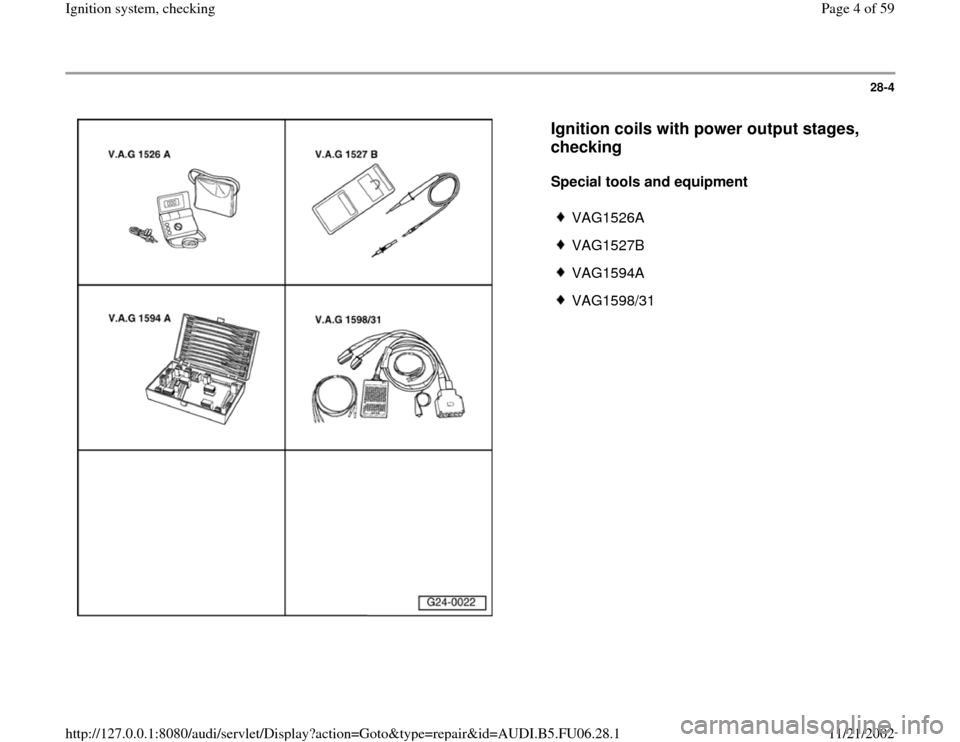
Ignition coils with power output stages,
checking
Special tools and equipment
VAG1526A
VAG1527B
VAG1594A
VAG1598/31
Pa
ge 4 of 59 I
gnition s
ystem, checkin
g
11/21/2002 htt
p://127.0.0.1:8080/audi/servlet/Dis
play?action=Goto&t
yp
e=re
pair&id=AUDI.B5.FU06.28.1
Page 5 of 59
28-5
Test sequence
Note:
The ignition coil and power output stage are
combined in one complete component.
Recognize a non-functional or misfiring cylinder as follows:
If misfires were recognized:
If no misfires were recognized:
or
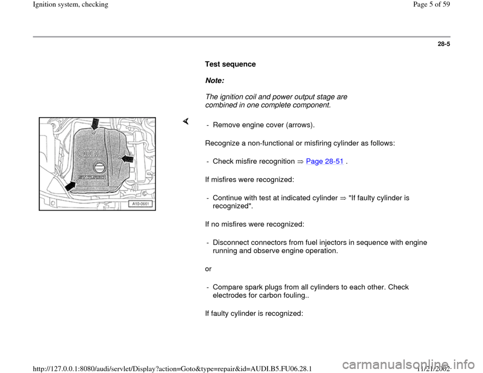
If faulty cylinder is recognized: - Remove engine cover (arrows).
- Check misfire recognition Page 28
-51
.
- Continue with test at indicated cylinder "If faulty cylinder is
recognized". - Disconnect connectors from fuel injectors in sequence with engine
running and observe engine operation.
- Compare spark plugs from all cylinders to each other. Check
electrodes for carbon fouling..
Pa
ge 5 of 59 I
gnition s
ystem, checkin
g
11/21/2002 htt
p://127.0.0.1:8080/audi/servlet/Dis
play?action=Goto&t
yp
e=re
pair&id=AUDI.B5.FU06.28.1
Page 7 of 59
28-6
If malfunction follows the spark plug:
- Replace spark plug.
If malfunction remains at original cylinder:
- Switch ignition coil from faulty cylinder with one
from another cylinder.
If malfunction follows the ignition coil:
- Replace ignition coil.
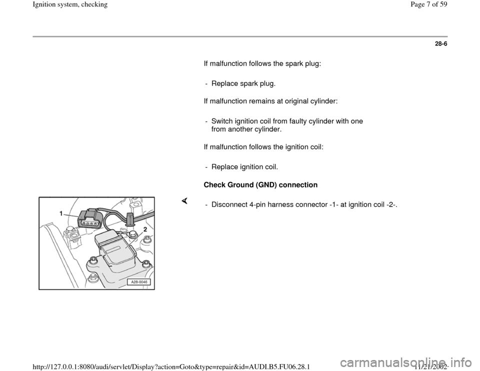
Check Ground (GND) connection
- Disconnect 4-pin harness connector -1- at ignition coil -2-.
Pa
ge 7 of 59 I
gnition s
ystem, checkin
g
11/21/2002 htt
p://127.0.0.1:8080/audi/servlet/Dis
play?action=Goto&t
yp
e=re
pair&id=AUDI.B5.FU06.28.1
Page 11 of 59
28-10
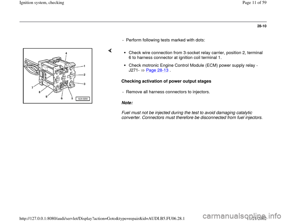
- Perform following tests marked with dots:
Checking activation of power output stages
Note:
Fuel must not be injected during the test to avoid damaging catalytic
converter. Connectors must therefore be disconnected from fuel injectors.
Check wire connection from 3-socket relay carrier, position 2, terminal
6 to harness connector at ignition coil terminal 1. Check motronic Engine Control Module (ECM) power supply relay -
J271- Page 28
-13
.
- Remove all harness connectors to injectors.
Pa
ge 11 of 59 I
gnition s
ystem, checkin
g
11/21/2002 htt
p://127.0.0.1:8080/audi/servlet/Dis
play?action=Goto&t
yp
e=re
pair&id=AUDI.B5.FU06.28.1
Page 12 of 59
28-11
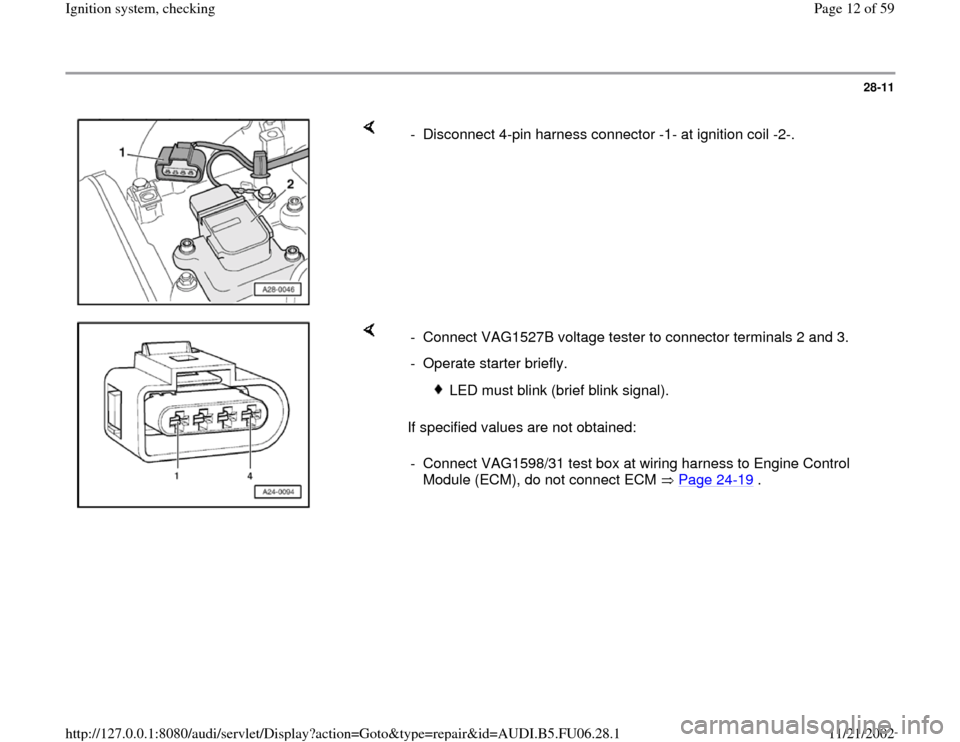
- Disconnect 4-pin harness connector -1- at ignition coil -2-.
If specified values are not obtained: - Connect VAG1527B voltage tester to connector terminals 2 and 3.
- Operate starter briefly.
LED must blink (brief blink signal).
- Connect VAG1598/31 test box at wiring harness to Engine Control
Module (ECM), do not connect ECM Page 24
-19
.
Pa
ge 12 of 59 I
gnition s
ystem, checkin
g
11/21/2002 htt
p://127.0.0.1:8080/audi/servlet/Dis
play?action=Goto&t
yp
e=re
pair&id=AUDI.B5.FU06.28.1
Page 13 of 59
28-12
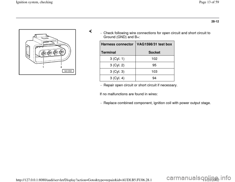
If no malfunctions are found in wires: - Check following wire connections for open circuit and short circuit to
Ground (GND) and B+: Harness connector
Terminal
VAG1598/31 test box
Socket
3 (Cyl. 1) 102
3 (Cyl. 2) 95
3 (Cyl. 3) 103
3 (Cyl. 4) 94
- Repair open circuit or short circuit if necessary.
- Replace combined component, ignition coil with power output stage.
Pa
ge 13 of 59 I
gnition s
ystem, checkin
g
11/21/2002 htt
p://127.0.0.1:8080/audi/servlet/Dis
play?action=Goto&t
yp
e=re
pair&id=AUDI.B5.FU06.28.1
Page 15 of 59
28-14
Note:
The motronic Engine Control Module (ECM)
power supply relay -J271- supplies voltage to the
ignition coils with power output stages and the
Engine Control Module (ECM) at pin 121.
Test requirement:
Fuses for engine electronics OK
Electrical Wiring Diagrams, Troubleshooting &
Component Locations
Test sequence
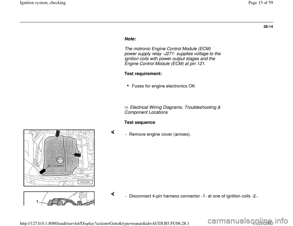
- Remove engine cover (arrows).
- Disconnect 4-pin harness connector -1- at one of ignition coils -2-.
Pa
ge 15 of 59 I
gnition s
ystem, checkin
g
11/21/2002 htt
p://127.0.0.1:8080/audi/servlet/Dis
play?action=Goto&t
yp
e=re
pair&id=AUDI.B5.FU06.28.1
Page 18 of 59
28-17
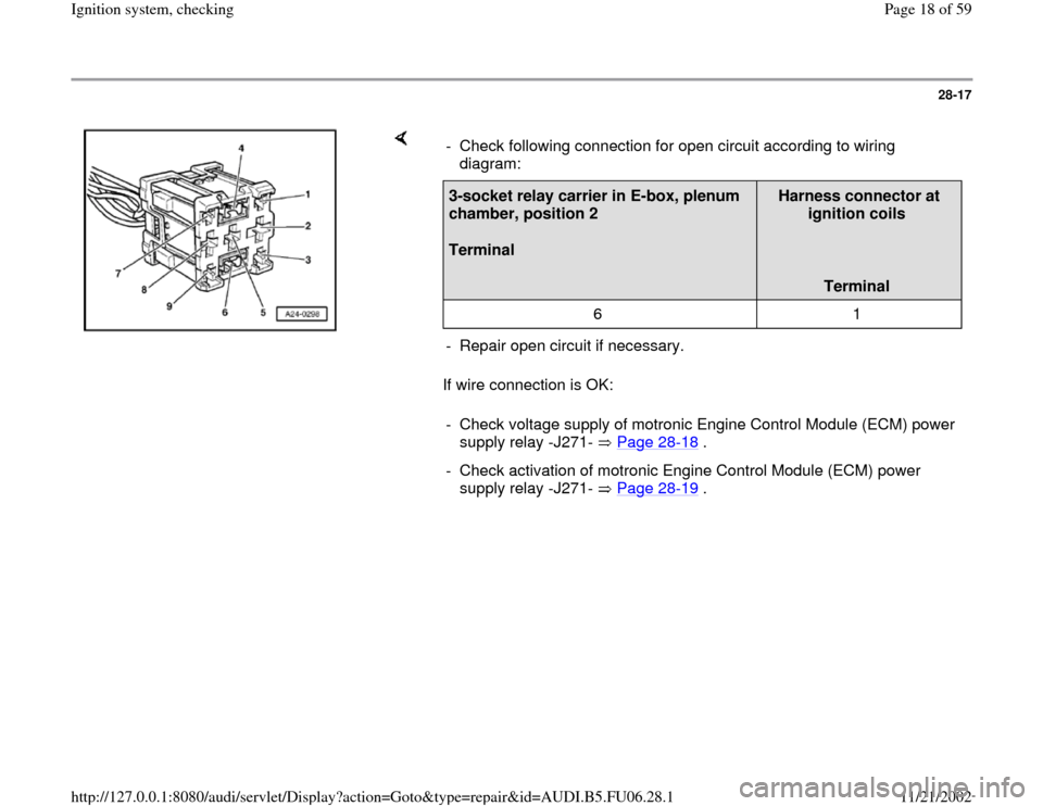
If wire connection is OK: - Check following connection for open circuit according to wiring
diagram: 3-socket relay carrier in E-box, plenum
chamber, position 2
Terminal
Harness connector at
ignition coils
Terminal
6 1
- Repair open circuit if necessary.
- Check voltage supply of motronic Engine Control Module (ECM) power
supply relay -J271- Page 28
-18
.
- Check activation of motronic Engine Control Module (ECM) power
supply relay -J271- Page 28
-19
.
Pa
ge 18 of 59 I
gnition s
ystem, checkin
g
11/21/2002 htt
p://127.0.0.1:8080/audi/servlet/Dis
play?action=Goto&t
yp
e=re
pair&id=AUDI.B5.FU06.28.1