AUDI A3 1996 8L / 1.G ATW Engine Motronic Fuel Injection Syst
Manufacturer: AUDI, Model Year: 1996,
Model line: A3,
Model: AUDI A3 1996 8L / 1.G
Pages: 81, PDF Size: 1.03 MB
AUDI A3 1996 8L / 1.G ATW Engine Motronic Fuel Injection Syst
A3 1996 8L / 1.G
AUDI
AUDI
https://www.carmanualsonline.info/img/6/1078/w960_1078-0.png
AUDI A3 1996 8L / 1.G ATW Engine Motronic Fuel Injection Syst
Trending: torque, warning light, fuse box, ECO mode, ECU, fuse box location, battery
Page 41 of 81
24-37
If pressure drops again:
- Check wire connections, O-rings at fuel
distributor and fuel injectors for proper seal.
- Check whether pressure gauge is properly
sealed.
Note:
Before disconnecting pressure gauge, release
pressure by opening shut-off valve. Hold a
container in front of connection for this.
Pa
ge 41 of 81 Motronic fuel in
jection s
ystem, servicin
g
11/21/2002 htt
p://127.0.0.1:8080/audi/servlet/Dis
play?action=Goto&t
yp
e=re
pair&id=AUDI.B5.FU06.24.1
Page 42 of 81
24-38
Fuel injectors, checking
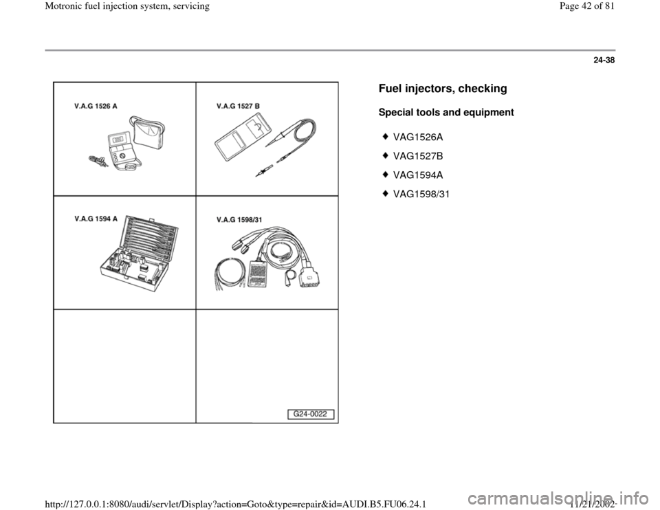
Special tools and equipment
VAG1526A
VAG1527B
VAG1594A
VAG1598/31
Pa
ge 42 of 81 Motronic fuel in
jection s
ystem, servicin
g
11/21/2002 htt
p://127.0.0.1:8080/audi/servlet/Dis
play?action=Goto&t
yp
e=re
pair&id=AUDI.B5.FU06.24.1
Page 43 of 81
24-39
Checking internal resistance
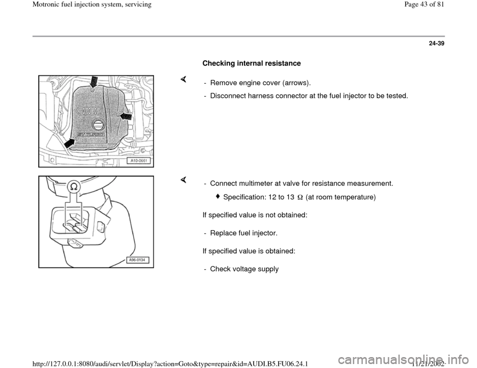
- Remove engine cover (arrows).
- Disconnect harness connector at the fuel injector to be tested.
If specified value is not obtained:
If specified value is obtained: - Connect multimeter at valve for resistance measurement.
Specification: 12 to 13 (at room temperature)
- Replace fuel injector.
- Check voltage supply
Pa
ge 43 of 81 Motronic fuel in
jection s
ystem, servicin
g
11/21/2002 htt
p://127.0.0.1:8080/audi/servlet/Dis
play?action=Goto&t
yp
e=re
pair&id=AUDI.B5.FU06.24.1
Page 44 of 81
24-40
Checking voltage supply
Test requirements:
Fuse for fuel injectors OK
Electrical Wiring Diagrams, Troubleshooting &
Component Locations
Fuel Pump (FP) relay OK; checking Page 24
-53
.
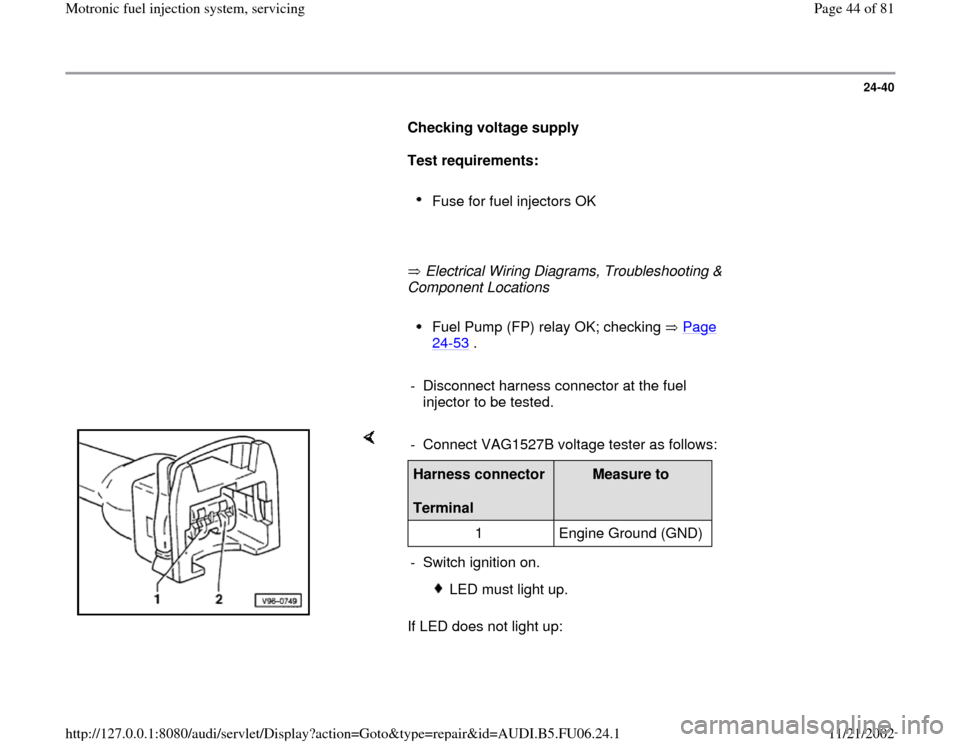
- Disconnect harness connector at the fuel
injector to be tested.
If LED does not light up: - Connect VAG1527B voltage tester as follows:Harness connector
Terminal
Measure to
1 Engine Ground (GND)
- Switch ignition on.
LED must light up.
Pa
ge 44 of 81 Motronic fuel in
jection s
ystem, servicin
g
11/21/2002 htt
p://127.0.0.1:8080/audi/servlet/Dis
play?action=Goto&t
yp
e=re
pair&id=AUDI.B5.FU06.24.1
Page 45 of 81
Electrical Wiring Diagrams, Troubleshooting & Component Locations - Check wire connection between terminal 1 and fuse for injector valves
for open circuit:
Pa
ge 45 of 81 Motronic fuel in
jection s
ystem, servicin
g
11/21/2002 htt
p://127.0.0.1:8080/audi/servlet/Dis
play?action=Goto&t
yp
e=re
pair&id=AUDI.B5.FU06.24.1
Page 46 of 81
24-41
- Repair open circuit if necessary.
If LED lights up:
- Activation of fuel injectors, checking
Checking activation
Test requirement:
Internal resistance of valve OK
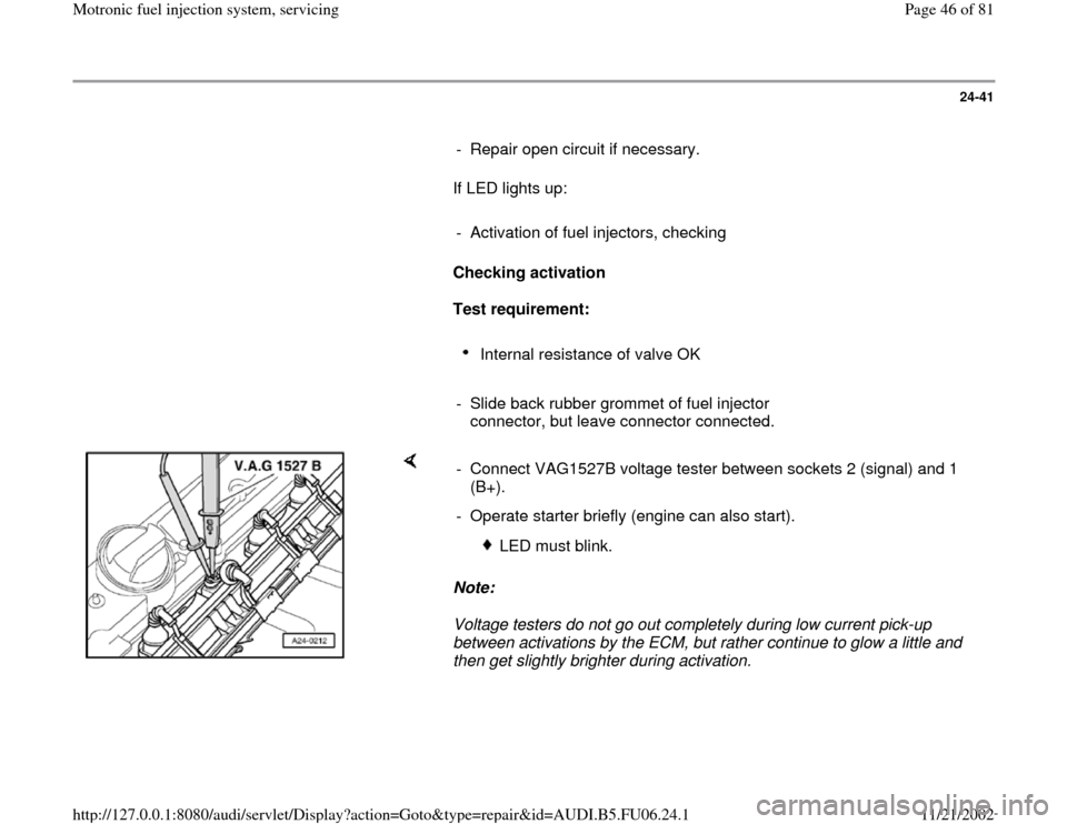
- Slide back rubber grommet of fuel injector
connector, but leave connector connected.
Note:
Voltage testers do not go out completely during low current pick-up
between activations by the ECM, but rather continue to glow a little and
then get slightly brighter during activation. - Connect VAG1527B voltage tester between sockets 2 (signal) and 1
(B+).
- Operate starter briefly (engine can also start).
LED must blink.
Pa
ge 46 of 81 Motronic fuel in
jection s
ystem, servicin
g
11/21/2002 htt
p://127.0.0.1:8080/audi/servlet/Dis
play?action=Goto&t
yp
e=re
pair&id=AUDI.B5.FU06.24.1
Page 47 of 81
24-42
If LED does not blink:
- Connect VAG1598/31 test box at wiring harness
to Engine Control Module (ECM), do not connect
ECM Page 24
-19
.
If wire connection is OK: - Check following wire connections for open circuit and short circuit to
Ground (GND) and B+: Cylinder
Fuel injector harness connector
Terminal
VAG1598/31 test box
Socket
1 2 96
2 2 89
3 2 97
4 2 88
- Repair open circuit or short circuit if necessary.
- Replace Engine Control Module (ECM) Page 24
-23
Pa
ge 47 of 81 Motronic fuel in
jection s
ystem, servicin
g
11/21/2002 htt
p://127.0.0.1:8080/audi/servlet/Dis
play?action=Goto&t
yp
e=re
pair&id=AUDI.B5.FU06.24.1
Page 48 of 81
24-43
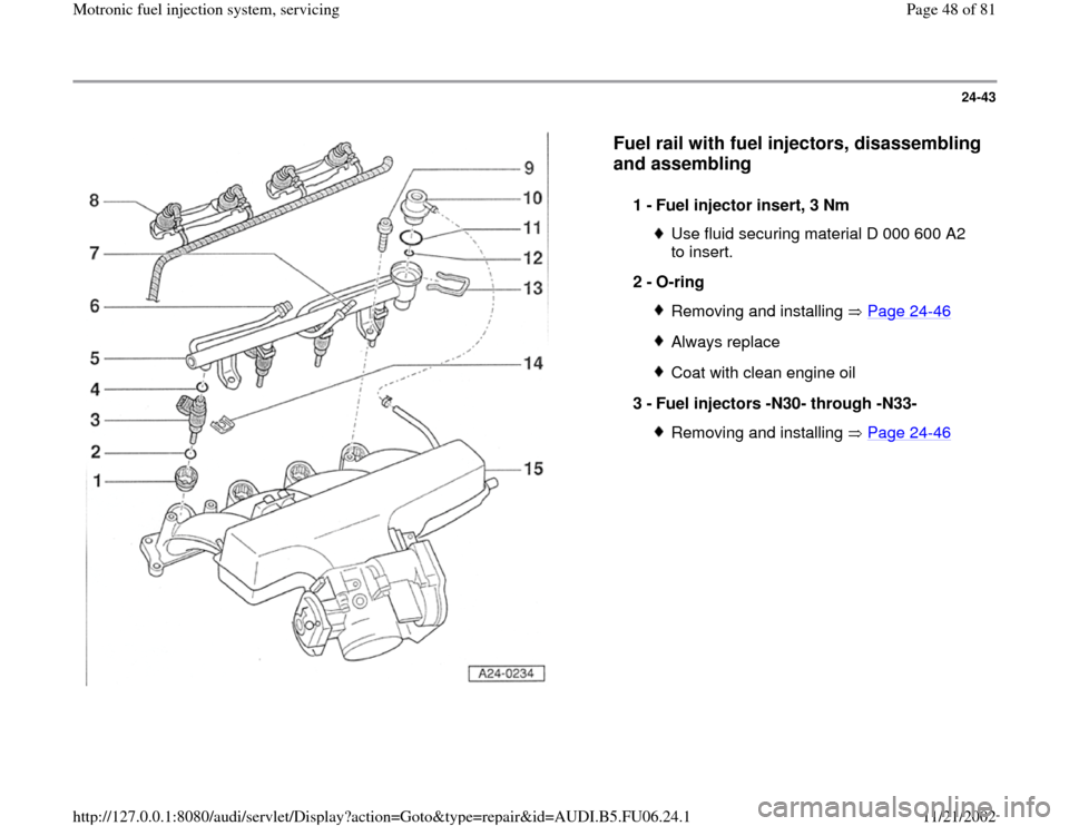
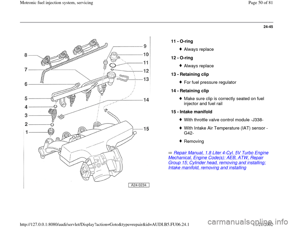
Fuel rail with fuel injectors, disassembling
and assembling
1 -
Fuel injector insert, 3 Nm
Use fluid securing material D 000 600 A2
to insert.
2 -
O-ring Removing and installing Page 24
-46
Always replaceCoat with clean engine oil
3 -
Fuel injectors -N30- through -N33- Removing and installing Page 24
-46
Pa
ge 48 of 81 Motronic fuel in
jection s
ystem, servicin
g
11/21/2002 htt
p://127.0.0.1:8080/audi/servlet/Dis
play?action=Goto&t
yp
e=re
pair&id=AUDI.B5.FU06.24.1
Page 49 of 81
24-44
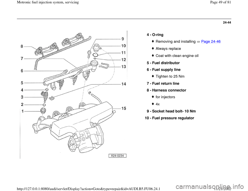
4 -
O-ring
Removing and installing Page 24
-46
Always replaceCoat with clean engine oil
5 -
Fuel distributor
6 -
Fuel supply line Tighten to 25 Nm
7 -
Fuel return line
8 -
Harness connector for injectors4x
9 -
Socket head bolt- 10 Nm
10 -
Fuel pressure regulator
Pa
ge 49 of 81 Motronic fuel in
jection s
ystem, servicin
g
11/21/2002 htt
p://127.0.0.1:8080/audi/servlet/Dis
play?action=Goto&t
yp
e=re
pair&id=AUDI.B5.FU06.24.1
Page 50 of 81
24-45
Repair Manual, 1.8 Liter 4
-Cyl. 5V Turbo Engine
Mechanical, Engine Code(s): AEB, ATW, Repair Group 15; Cylinder head, removing and installing; Intake manifold, removing and installing
11 -
O-ring
Always replace
12 -
O-ring Always replace
13 -
Retaining clip For fuel pressure regulator
14 -
Retaining clip Make sure clip is correctly seated on fuel
injector and fuel rail
15 -
Intake manifold With throttle valve control module -J338-With Intake Air Temperature (IAT) sensor -
G42- Removing
Pa
ge 50 of 81 Motronic fuel in
jection s
ystem, servicin
g
11/21/2002 htt
p://127.0.0.1:8080/audi/servlet/Dis
play?action=Goto&t
yp
e=re
pair&id=AUDI.B5.FU06.24.1
Trending: clutch, check engine, steering, immobilizer, check engine light, power steering, warning light
