lock AUDI A3 1997 8L / 1.G ATW Engine Ignition System Workshop Manual
[x] Cancel search | Manufacturer: AUDI, Model Year: 1997, Model line: A3, Model: AUDI A3 1997 8L / 1.GPages: 59, PDF Size: 0.53 MB
Page 1 of 59
28-1
Ignition system, checking
General notes on ignition system
Note:
The battery should only be disconnected and
reconnected when the ignition is turned off,
since otherwise the Engine Control Module
(ECM) can be damaged.
For the electric components to work properly, a
voltage of at least 12.7 V is required.
It is possible that the control module will
recognize a malfunction and store a DTC during
some tests. After completing all tests and
repairs, DTC memory should therefore be
checked and erased if necessary.
If the engine only starts briefly and then turns
off again after troubleshooting, repair or
checking of the components, it may be that the
immobilizer is blocking the Engine Control
Module (ECM). DTC memory must then be
checked and if necessary, control module must
be adapted.
Pa
ge 1 of 59 I
gnition s
ystem, checkin
g
11/21/2002 htt
p://127.0.0.1:8080/audi/servlet/Dis
play?action=Goto&t
yp
e=re
pair&id=AUDI.B5.FU06.28.1
Page 23 of 59
28-22
Component location Overview of component
locations Page 24
-5
Test sequence
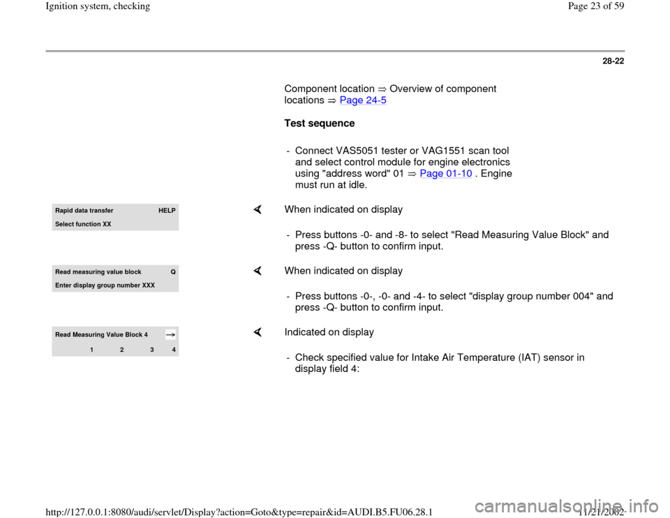
- Connect VAS5051 tester or VAG1551 scan tool
and select control module for engine electronics
using "address word" 01 Page 01
-10
. Engine
must run at idle.
Rapid data transfer
HELP
Select function XX
When indicated on display
- Press buttons -0- and -8- to select "Read Measuring Value Block" and
press -Q- button to confirm input.
Read measurin
g value block
Q
Enter display group number XXX
When indicated on display
- Press buttons -0-, -0- and -4- to select "display group number 004" and
press -Q- button to confirm input.
Read Measuring Value Block 4
1
2
3
4
Indicated on display
- Check specified value for Intake Air Temperature (IAT) sensor in
display field 4:
Pa
ge 23 of 59 I
gnition s
ystem, checkin
g
11/21/2002 htt
p://127.0.0.1:8080/audi/servlet/Dis
play?action=Goto&t
yp
e=re
pair&id=AUDI.B5.FU06.28.1
Page 32 of 59
28-31
Component location Overview of component
locations Page 24
-5
Test requirement:
Engine cold
Test sequence
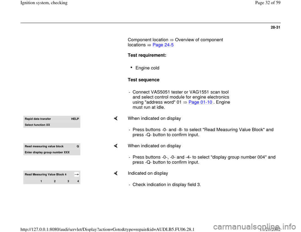
- Connect VAS5051 tester or VAG1551 scan tool
and select control module for engine electronics
using "address word" 01 Page 01
-10
. Engine
must run at idle.
Rapid data transfer
HELP
Select function XX
When indicated on display
- Press buttons -0- and -8- to select "Read Measuring Value Block" and
press -Q- button to confirm input.
Read measurin
g value block
Q
Enter displa
y group number XXX
When indicated on display
- Press buttons -0-, -0- and -4- to select "display group number 004" and
press -Q- button to confirm input.
Read Measuring Value Block 4
1
2
3
4
Indicated on display
- Check indication in display field 3.
Pa
ge 32 of 59 I
gnition s
ystem, checkin
g
11/21/2002 htt
p://127.0.0.1:8080/audi/servlet/Dis
play?action=Goto&t
yp
e=re
pair&id=AUDI.B5.FU06.28.1
Page 54 of 59
28-50
If, after erasing the DTC memory for a test, a DTC relating to the
Camshaft Position (CMP) sensor (hall sensor) is indicated again, even
though all previous tests were OK, the following malfunction is possible:
Repair Manual, 1.8 Liter 4
-Cyl. 5V Turbo Engine Mechanical, Engine
Code(s): AEB, ATW, Repair Group 15; Valvetrain, servicing
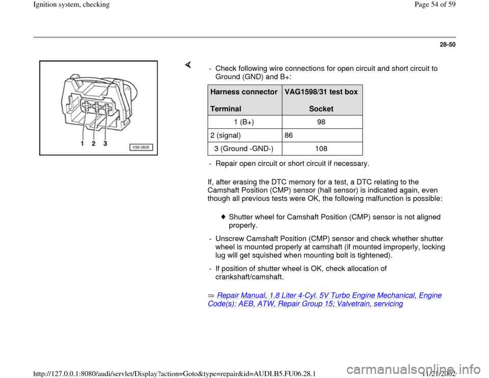
- Check following wire connections for open circuit and short circuit to
Ground (GND) and B+:
Harness connector
Terminal
VAG1598/31 test box
Socket
1 (B+) 98
2 (signal) 86
3 (Ground -GND-) 108
- Repair open circuit or short circuit if necessary.
Shutter wheel for Camshaft Position (CMP) sensor is not aligned
properly.
- Unscrew Camshaft Position (CMP) sensor and check whether shutter
wheel is mounted properly at camshaft (if mounted improperly, locking
lug will get squished when mounting bolt is tightened).
- If position of shutter wheel is OK, check allocation of
crankshaft/camshaft.
Pa
ge 54 of 59 I
gnition s
ystem, checkin
g
11/21/2002 htt
p://127.0.0.1:8080/audi/servlet/Dis
play?action=Goto&t
yp
e=re
pair&id=AUDI.B5.FU06.28.1
Page 55 of 59
28-51
Misfire recognition, checking
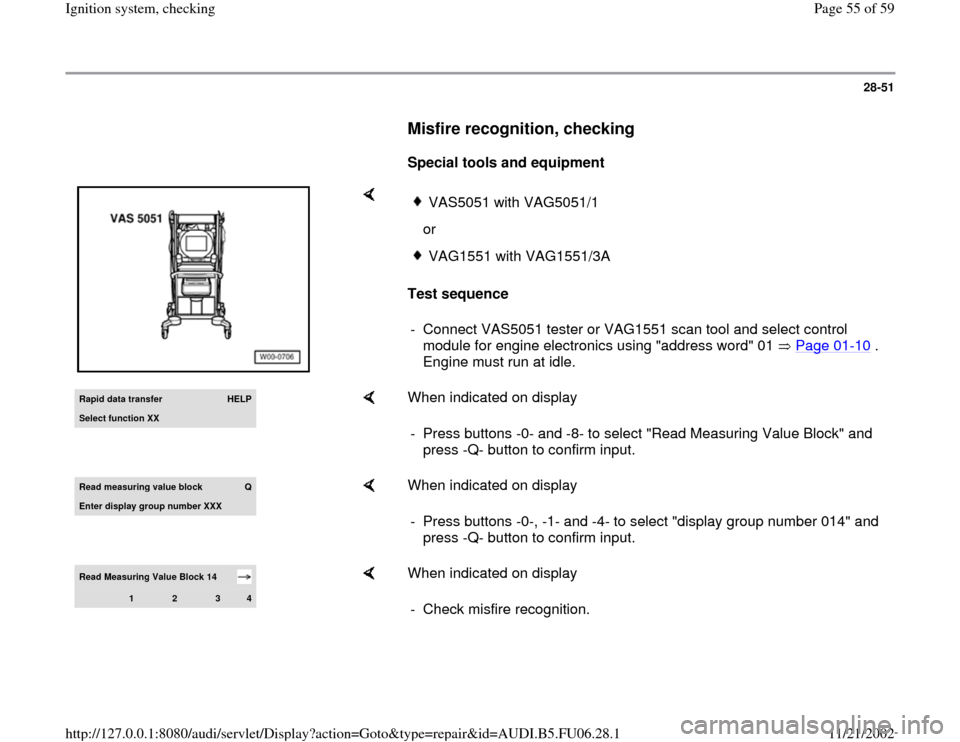
Special tools and equipment
Test sequence
VAS5051 with VAG5051/1
orVAG1551 with VAG1551/3A
- Connect VAS5051 tester or VAG1551 scan tool and select control
module for engine electronics using "address word" 01 Page 01
-10
.
Engine must run at idle.
Rapid data transfer
HELP
Select function XX
When indicated on display
- Press buttons -0- and -8- to select "Read Measuring Value Block" and
press -Q- button to confirm input.
Read measurin
g value block
Q
Enter displa
y group number XXX
When indicated on display
- Press buttons -0-, -1- and -4- to select "display group number 014" and
press -Q- button to confirm input.
Read Measuring Value Block 14
1
2
3
4
When indicated on display
- Check misfire recognition.
Pa
ge 55 of 59 I
gnition s
ystem, checkin
g
11/21/2002 htt
p://127.0.0.1:8080/audi/servlet/Dis
play?action=Goto&t
yp
e=re
pair&id=AUDI.B5.FU06.28.1
Page 56 of 59
28-52
Display fields
1 2 3 4
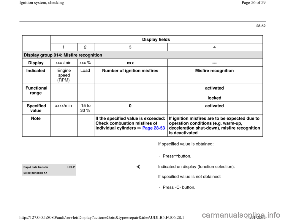
Display group 014: Misfire recognition
Display xxx /min xxx %
xxx
---
Indicated Engine
speed
(RPM) Load
Number of ignition misfires
Misfire recognition
Functional
range
activated
locked
Specified
value xxxx/min 15 to
33 % 0
activated
Note
If the specified value is exceeded:
Check combustion misfires of
individual cylinders Page 28
-53
If ignition misfires are to be expected due to
operation conditions (e.g. warm-up,
deceleration shut-down), misfire recognition
is deactivated
If specified value is obtained:
-
Press button.Rapid data transfer
HELP
Select function XX
Indicated on display (function selection):
If specified value is not obtained:
- Press -C- button.
Pa
ge 56 of 59 I
gnition s
ystem, checkin
g
11/21/2002 htt
p://127.0.0.1:8080/audi/servlet/Dis
play?action=Goto&t
yp
e=re
pair&id=AUDI.B5.FU06.28.1
Page 57 of 59
28-53
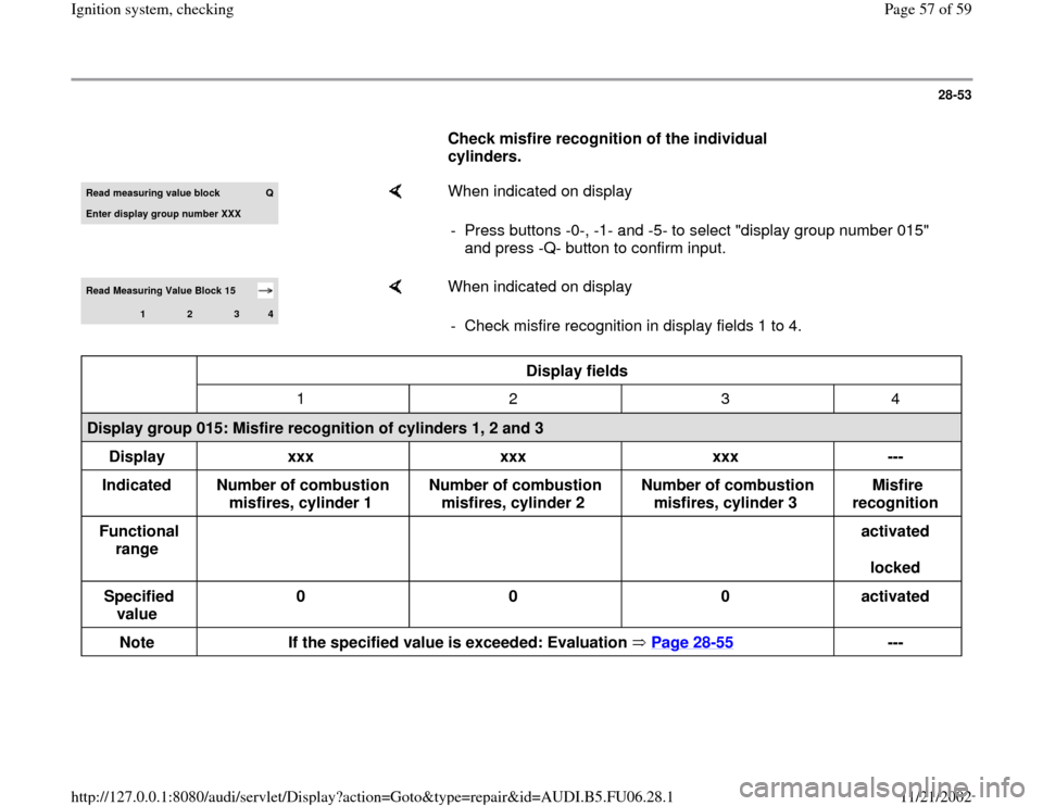
Check misfire recognition of the individual
cylinders. Read measuring value block
Q
Enter display group number XXX
When indicated on display
- Press buttons -0-, -1- and -5- to select "display group number 015"
and press -Q- button to confirm input.
Read Measuring Value Block 15
1
2
3
4
When indicated on display
- Check misfire recognition in display fields 1 to 4.
Display fields
1 2 3 4
Display group 015: Misfire recognition of cylinders 1, 2 and 3
Display
xxx
xxx
xxx
---
Indicated
Number of combustion
misfires, cylinder 1 Number of combustion
misfires, cylinder 2 Number of combustion
misfires, cylinder 3 Misfire
recognition
Functional
range
activated
locked
Specified
value 0
0
0
activated
Note
If the specified value is exceeded: Evaluation Page 28
-55
--- Pa
ge 57 of 59 I
gnition s
ystem, checkin
g
11/21/2002 htt
p://127.0.0.1:8080/audi/servlet/Dis
play?action=Goto&t
yp
e=re
pair&id=AUDI.B5.FU06.28.1
Page 58 of 59
28-54
- Press -C- button.Read measuring value block
Q
Enter display group number XXX
When indicated on display
- Press buttons -0-, -1- and -6- to select "display group number 016" and
press -Q- button to confirm input.
Read Measuring Value Block 16
1
2
3
4
When indicated on display
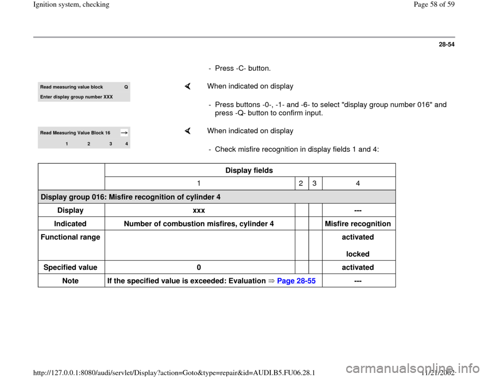
- Check misfire recognition in display fields 1 and 4:
Display fields
1 2 3 4
Display group 016: Misfire recognition of cylinder 4
Display
xxx
---
Indicated
Number of combustion misfires, cylinder 4
Misfire recognition
Functional range
activated
locked
Specified value
0
activated
Note
If the specified value is exceeded: Evaluation Page 28
-55
---
Pa
ge 58 of 59 I
gnition s
ystem, checkin
g
11/21/2002 htt
p://127.0.0.1:8080/audi/servlet/Dis
play?action=Goto&t
yp
e=re
pair&id=AUDI.B5.FU06.28.1