clock AUDI A3 2011 Owner´s Manual
[x] Cancel search | Manufacturer: AUDI, Model Year: 2011, Model line: A3, Model: AUDI A3 2011Pages: 320, PDF Size: 75.79 MB
Page 11 of 320
If the engine RPMs drop below 1 500, you should downshift to the
next lower gear. The red area at the end of the scale indicates
maximum permissible engine RPMs after the break-in period. Before
reach ing this area, you should either shift into the next higher gear or
ease your foot off the accelerator pedal.
0 Note
The tachometer needle=> page 8, fig. 2 © should not move into the
red range. If it does, then only for a very short period of time. You
could damage your engine by driv ing at high RPM!
<£> For the sake of the environment
Upshifting early saves fuels and reduces engine noise. •
Digital clock with date display
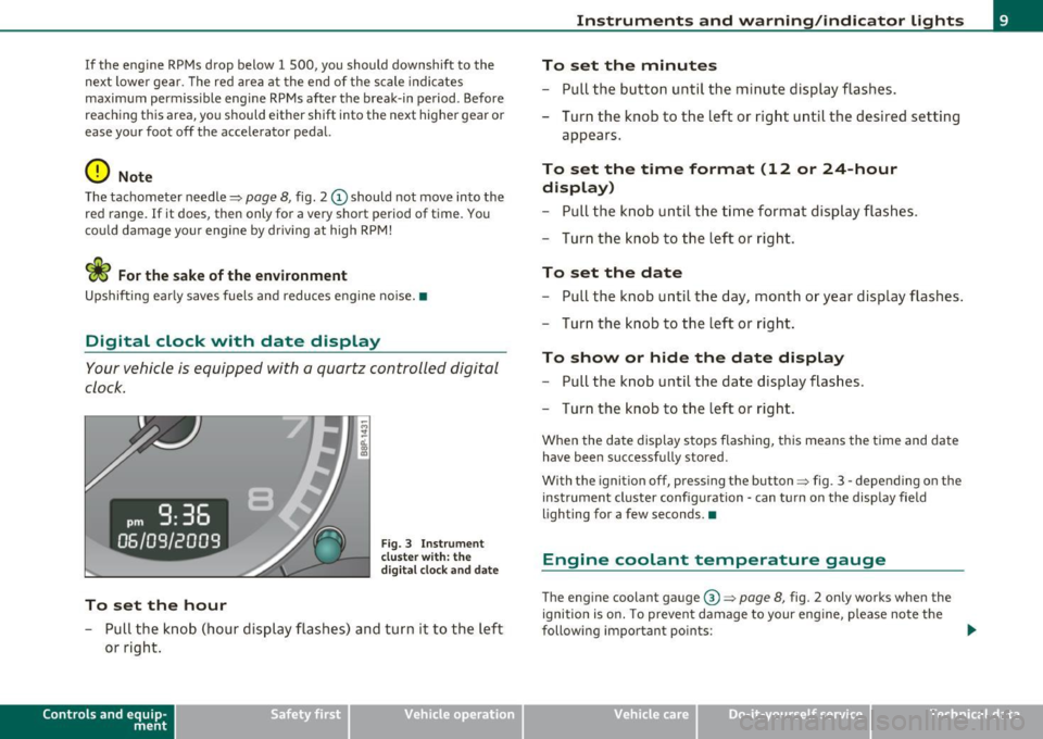
Your vehicle is equipped with a quartz controlled digital
clock.
To set the hour
Fig. 3 Instrume nt
cl uste r with: the
digital clock and date
- Pull the knob (hour display flashes) and turn it to the left
or right.
Con tro ls a nd e quip
m en t Vehicle
OP-eration
Instruments and warning /indicator lights
To set the minutes
- Pull the button until the minute display flashes.
- Turn the knob to the left or right until the desired setting
appears.
To set the time format (12 or 24-hour
display)
- Pull the knob until the time format display flashes.
- Turn the knob to the left or right.
To set the date
- Pull the knob until the day, month or year display flashes .
- Turn the knob to the left or right .
To show or hide the date display
-Pull the knob until the date display flashes.
- Turn the knob to the left or right.
When the date display stops flashing, this means the time and date
have been successfu lly stored .
With the ignition off, pressing the button=> fig . 3 - depending on the
instrument cl uster configuration - can turn on the display fie ld
lighting for a few seconds. •
Engine coolant temperature gauge
The engine coolant gauge@=> page 8, fig. 2 only works when the
ignition is on. To prevent damage to your eng ine , please note the
following important points: .,_
Vehicle care Do-it-yourselt service iTechnical data
Page 13 of 320
Lower odometer
The lowe r odometer shows the total number of mi les (k ilometers)
driven .
Upper odometer (trip odometer)
The upper odometer shows the total number of m iles (kilometers)
driven since you last reset the odometer back to zero . Yo u can use th is
odometer when you want to keep track of how many m iles (k ilome
ters) you have dr iven for a sing le trip or er rand. The last dig it indicates
1 /10 of a mi le ( 100 metres) . You can set the trip odome ter back to
zero by pressing the reset button=>
page 10, fig. 4.
Malfunction message
If there is a ma lfunction somewhe re in the instr ument cl uster, dEF
will appear in the trip odometer and will stay on. Contact you r autho
r ized A udi dea ler to have the problem corrected .
Immobilizer
When the ignition is switched on, the da ta on the igni tion key are
scanned automatically.
If an una uthorized key was used,
SAFE is disp layed continuous ly in
t he o dome ter di sp la y field. The vehicle ca nnot be operated
=> page 40.
[ i J Tips
• The d ig ita l clock and the odometer are turned on for about 30
seconds when the driver's do or is ope ned.
• When the ignition is turned off, t he odomete r reading and the
dig it al cl ock wi th date di sp la y can be sw itche d on for abou t
30 seconds by press ing the knob::::;,
page 8, fig. 2 @ . •
Con tro ls a nd e quip
m en t Vehicle
OP-eration
Instruments and warning /indicator lights
Warning/indicator lights
Overview
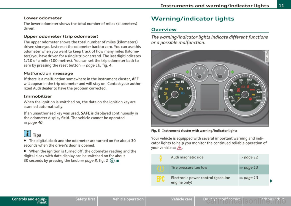
The w arni ng/in dicator lights ind icate differ ent fun ctions
o r a po ssible m alfunc tio n.
Fig. 5 In strument clu ster w ith warn ing /ind ica tor light s
Your vehicle is equipped with several important warning and indi
c ato r lights to help yo u m onito r th e con tinued re liable operat io n o f
your vehicle ::::;,& .
Aud i ma gnetic ride
Tire pressure too low Electronic power control (gasoline
engine o nly)
=> page 12
=:> page 13
=> page 13
Vehicle care Do-it-yourselt service iTechnical data
Page 31 of 320
Speed warning 1: setting a speed Limit
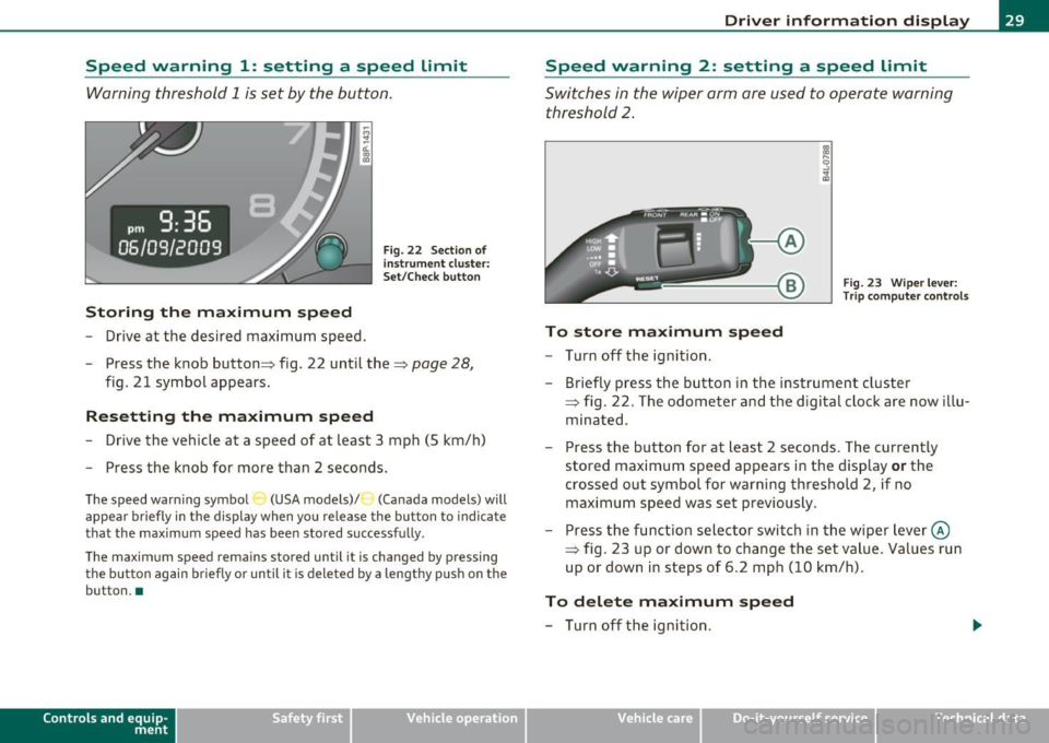
Warning threshold 1 is set by the button.
Storing the maximum speed
- Drive at the desired maximum speed.
Fig. 22 Section o f
in st rum ent cluster:
Set/Check button
- Press the knob button :::} fig. 22 until the :::} page 28,
fig. 21 symbol appears.
Resetting the maximum speed
- Drive the vehicle at a speed of at least 3 mph (5 km/h)
- Press the knob for more than 2 seconds.
The speed warning symbo l (USA models) /') (Canada models) will
appear briefly in the display when you release the button to indicate
that the maximum speed has been stored successfully .
The maximum speed remains stored until it is changed by pressing the button again briefly or until it is deleted by a lengthy push on the
button. •
Contro ls a nd e quip
m en t Vehicle
OP-eration
Driver information display
Speed warning 2: setting a speed Limit
Switches in the wiper arm are used to operate warning
threshold
2.
Fig. 23 Wiper lever:
Trip computer controls
To store maximum speed
- Turn off the ignition.
- Briefly press the button in the instrument cluster
=> fig. 22. The odometer and the d igital clock are now illu
minated .
- Press the button for at least 2 seconds. The currently
stored maximum speed appears in the display
or the
crossed out symbol for warning threshold 2, if no maximum speed was set previously .
- Press the function selector switch in the wiper lever@
=> fig. 23 up or down to change the set value . Values run
up or down in steps of 6.2 mph (10 km/h).
To delete maximum speed
- Turn off the ignition.
Vehicle care Do-it-yourselt service iTechnical data
Page 32 of 320
Driver info rmation d isplay
- Briefly press the button in the instrument cluster
=>
page 29, fig . 22. The odometer and the digital clock are
now i lluminated .
- Press the button for at least 2 seconds . The currently
stored maximum speed appears in the display.
- Press the reset button in the wiper lever@=>
page 29,
fig. 23 until the crossed out speed warning symbol for
warning th reshold 2 appears in the display.
A few seconds after the ad justment is completed, the illuminat io n for
the odometer and the digital clock will go out.
[ i J Tips
This warning thresho ld can also be contro lled through the trip
computer~
page 24, "Navigat ing the menu" .•
Warnings and symbols
Red symbols
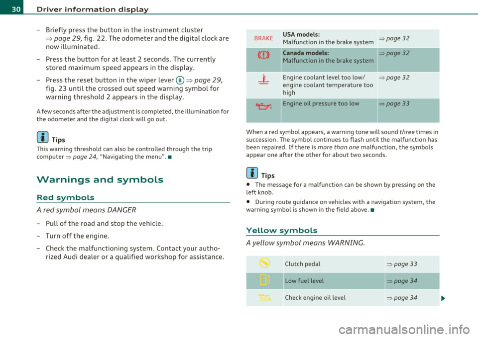
A red symbol means DANGER
- P ull of the road and stop the vehicle .
- Turn off the engine.
- Check the malfunctioning syst em. Contact you r au tho-
rized Audi dealer or a qualified workshop for assistance.
BRAKE USA models : ~page32 Malfunction in the brake system
Canada models : ~page32
Malfunction in the brake system
_i_ Engine coolant level too low/ ~page32
-engine coolant temperat ure too
high
~ Engine oil pressure too low ~page33
When a red symbo l appears , a warn ing tone will sound three t imes in
succession. The symbo l continues to flash until the malfunction has
bee n repaired. If there is
more than one malfunction , the symbols
appear one after the other for about two seconds.
[ i J Tips
• The message for a malfunction can be shown by pressing on the
left knob.
• During route guidance on vehicles with a navigat ion system, the
wa rni ng symbo l is shown in the fie ld above. •
Yellow symbols
Ayellow symbol means WARNING.
Clutch pedal ~page33
- -
Low fuel level ~page34
Check eng ine oi l level ~ page34
Page 56 of 320
Open ing and closing
App lies to veh icles : w ith panoramic sliding sunroof
Removing the light unit
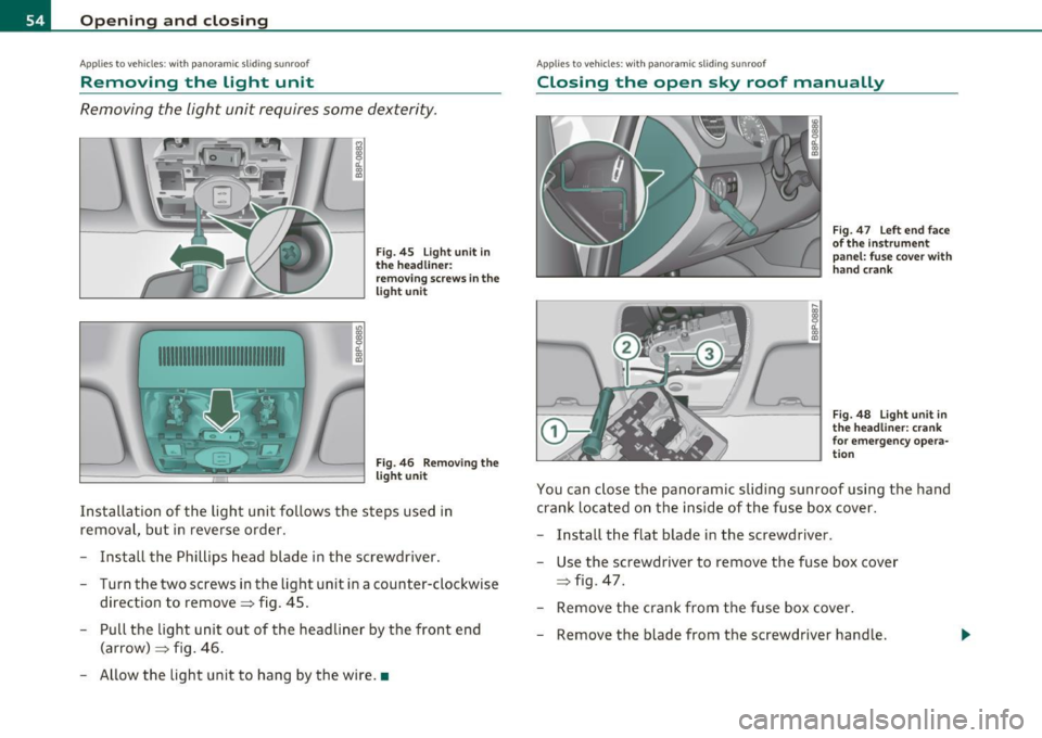
Removing the light unit requires some dexterity .
1111111111111111111111111111111
.,
~ CL ., m
"' ~ CL ., m
Fig. 45 Light unit in
t he headliner:
removing screws in the
light unit
Fig. 46 Removing the
light unit
Installation of the light unit follows the steps used in
removal, but in reverse order.
- Install the Phillips head blade in the screwdriver.
- Turn the two screws in the light unit in a counter-clockwise direction to remove~ fig. 45.
- Pull the light unit out of the headliner by the front end
(arrow) ~ fig. 46 .
- Allow the light unit to hang by the wire. •
Applies to vehicles : w ith panoramic sliding sunroof
Closing the open sky roof manually
Fig. 47 Left end face
of t he inst rument
panel: fuse cove r wit h
hand crank
F ig. 48 Lig ht unit in
t h e hea dliner : cran k
for emergency opera
t io n
You can close the panoramic sliding sunroof using the hand
crank located on the inside of the fuse box cover .
- Install the flat blade in the screwdriver .
Use the screwdriver to remove the fuse box cover
~ fig . 47 .
- Remove the crank from the fuse box cover .
Remove the blade from the screwdriver handle .
Page 107 of 320
___________________________________________________ O_ n_ t_h _e_ r_o _a_ d __ _
On the road
Steering
Adjustable steering wheel
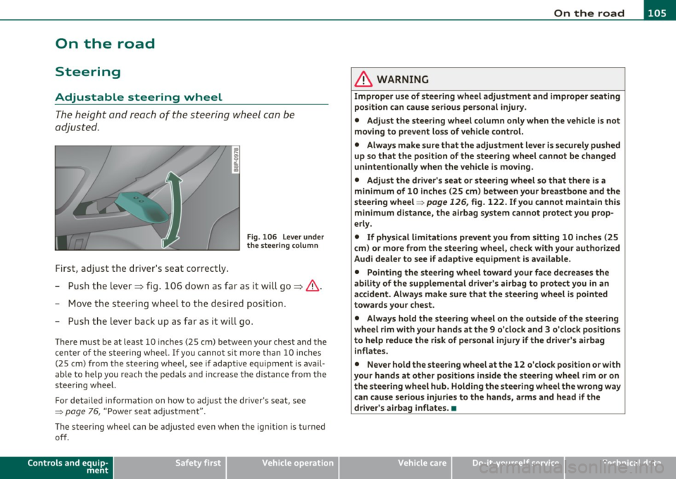
The height and reach of the steering wheel con be
adjusted .
First, adjust t he dr iver's seat correct ly.
Fi g. 106 Leve r und er
the s tee ring column
-Pu sh t he lever~ fig. 106 down as far as it wi ll go~ &.
- Move th e st eeri ng wheel to t he desire d position.
- Push t he lever back up as fa r as it wi ll go.
There must be at least 10 inches (25 cm) between your chest and the
c en ter of the steer ing w hee l. If you cannot si t more than 10 inches
(25 cm) from the steering wheel, see if adaptive equ ipment is avai l
able to help you reach the pedals and increase the distance from the
steeri ng wheel.
For detai led info rmation on how to adjust the dr iver's seat, see
=> page 76, "Power se at adj ustment".
The steer ing whee l can be adjusted even when the ignition is turned
off .
Controls and equip
ment Safety first
& WARNING
Improper use of steering wheel adjustment and improper seating
position can cause serious personal
injury .
• Adjust the steer ing whe el column only when the vehicle is not
moving to prevent loss of vehicle control.
• Always make sure that the adjustment lever is securely pushed
up so that the position of the steering wheel cannot be changed
unintentionally when the vehicle is moving .
• Adjust the dr iver 's seat or steering wheel so that there is a
m inimum of 10 inches (25 cm) between your breastbone and the
steering wheel=>
page 126, fig. 122. If you cannot maintain this
minimum distance, the airbag system cannot protect you prop
erly.
• If physical limitations prevent you from sitting 10 inches (25
c m) or more from the steering wheel, check with your authorized
Audi dealer to see if adaptive equipment is available .
• Pointing the steering wheel toward your face decrea ses the
ability of the supplemental driver's a irbag to prote ct you in an
accident. Always make sure that the steer ing wheel is pointed
towards your che st .
• Always hold the steering wheel on the outside of the steering
wheel rim with your hands at the 9 o'clo ck and 3 o'clock position s
to help reduce the risk of personal injury if the driver's airbag
inflates .
• Never hold the steer ing wheel at the 12 o 'clock position or with
your hands at other positions inside the steering wheel rim or on
the steering wheel hub. Holding the steering wheel the wrong way
can cause serious injurie s to the hand s, arms and head if th e
driver 's airbag inflates. •
Vehicle care Technical data
Page 128 of 320
• ....__D_ r_iv _i_ n_, g=-- S_ a _ f_e _,Ly _ ______________________________________________ _
Proper occupant seating positions
Proper seating position for the driver
The proper driver seating position is important for safe,
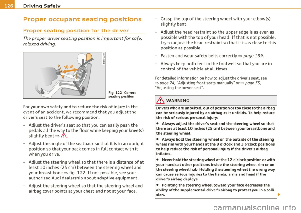
relaxed driving.
Fig. 122 Correct
seating position
For your own safety and to reduce the risk of injury in the
event of an accident, we recommend that you adjust the
driver's seat to the following position:
- Adjust the driver's seat so that you can easily push the
pedals all the way to the floor while keeping your knee(s)
slightly bent~& .
- Adjust the angle of the seatback so that it is in an upright
pos ition so that your back comes in full contact with it
when you drive.
- Adjust the steering wheel so that there is a distance of at least 10 inches (25 cm) between the steering wheel and
your breast bone~ fig . 122. If not possible, see your
authorized Audi dealership about adaptive equipment.
- Adjust the steering wheel so that the steering wheel and airbag cover points at your chest and not at your face. -
Grasp the top of the steering wheel with your elbow(s)
slightly bent.
- Adjust the head restraint so the upper edge is as even as
possible with the top of your head. If that is not possible,
try to adjust the head restraint so that it is as close to this
position as possible.
- Fasten and wear safety belts correctly~
page 139.
-Always keep both feet in the footwell so that you are in
control of the vehicle at all t imes.
F o r deta iled informat ion on how to adjust the d river 's seat, see
=>
page 74 , "Adjusting front seats manually " or => pag e 75,
"Adjus ting the power sea t".
& WARNING
Drivers who are unbelted, out of position or too close to the airbag
can be seriously injured by an airbag as it unfolds. To help reduce
the risk of serious personal injury:
• Always adjust the driver's seat and the steering wheel so that
there are at least 10 inches (25 cm) between your breastbone and
the steering wheel.
• Always hold the steering wheel on the outside of the steering
wheel rim with your hands at the 9 o'clock and 3 o'clock positions
to help reduce the risk of personal injury if the driver's airbag
inflates.
• Never hold the steering wheel at the 12 o'clock position or with
your hands at other positions inside the steering wheel rim or on
the steering wheel hub. Holding the steering wheel the wrong way
can cause serious injuries to the hands, arms and head if the
driver's airbag deploys.
• Pointing the steering wheel toward your face decreases the
ability of the supplemental driver's airbag to protect you in a colli·
sion. .,
Page 224 of 320
-Fuel supply and filling your fuel tank PHf_ -:.....:.-.:._____ --------=-.:-___________ _
& WARNING
Under normal operating conditions, never carry additional fuel
containers in your car. Gas canisters and other containers used to
transport fuel can be dangerous. Such containers, full or empty,
may leak and could cause a fire in a collision. If you must transport
fuel to use for your lawn mower, snow blower, etc., be very careful
and always observe local and state laws regarding the use, trans
portation and storage of such fuel containers. Make certain the
container meets industry standards (ANSI/ASTM F852 - 86).
0 Note
Never drive your vehicle until the fuel tank is completely dry. The
irregular supply of fuel can cause misfiring. Gasoline could enter into
the exhaust system and damage the catalytic converter. •
Refuelling
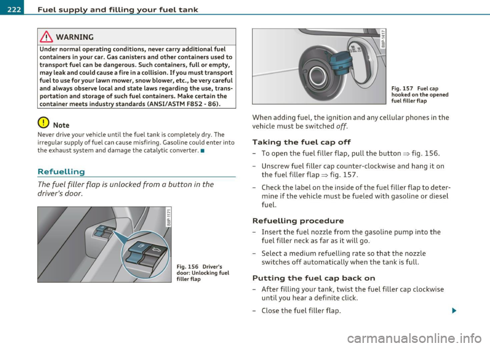
The fuel filler flap is unlocked from a button in the
driver's door.
Fig . 156 Driver's
door: Unlocking fuel
filler flap Fig
. 157 Fuel cap
hooked on the opened
fuel filler flap
When adding fuel, the ignition and any cellular phones in the
vehicle must be switched
off.
Taking the fuel cap off
- To open the fuel filler flap, pull the button=> fig. 156 .
- Unscrew fuel filler cap counter-clockwise and hang it on
the fuel filler flap => fig . 157.
- Check the label on the inside of the fuel filler flap to deter
mine if the vehicle must be fueled with gasoline or diesel
fuel.
Refuelling procedure
Insert the fuel nozzle from the gasoline pump into the
fuel filler neck as far as it will go.
- Select a medium refuelling rate so that the nozzle
switches off automatically when the tank is full.
Putting the fuel cap back on
-After filling your tank, twist the fuel filler cap clockwise
until you hear a definite click.
- Close the fuel filler flap. .,
Page 238 of 320
___ C_ h_ e_c _k _i _ n _g ~ a_n _d_ f_il _l_in _ g _________________________________________ _
level sensor, we still recommend you check the coolant leve l from
ti me to time.
Coolant loss
Coolan t loss may ind ic a te a leak in the coo ling sys tem. In the event of
coo lant loss, the cooli ng system should be inspected immed iately by
your au thor ized A udi dealer.
It is no t enough merely to add coolan t.
In a
s ealed system, losses can occur only if the boiling point of the
coo lant is exceeded as a res ult of overheating .
(D Note
Do not add any type of radiator leak sealant to yo ur vehicle's engine
c oo lant. Addi ng radia tor repa ir fluid m ay adverse ly affect the fun c
tion and perfo rmance of your cooling system and could result in
damage not cove red by yo ur New Vehi cle Lim ited Warranty .•
Adding coolant
B e very careful when adding engine coolant.
Before you check anyt hing in the eng ine compartment ,
always read and heed all WARNINGS=> & in " Working i n
the e ngine compartment" on page
226.
-Tur n off the eng ine.
- Let t he engi ne c ool d ow n.
- Place a thick rag over the coolant expansion tank
=> pa ge 235, fig . 166 and carefully twist t he cap cou nte r
clockwis e
=> &.
- Add coo lant.
- Tw ist the ca p on aga in
tightly .
Replacement eng ine coolant must conform to exact spec ificat ions
=> page 234, " Coolant" . Even in a n emergency, if coolant additive
Gl2 ++. Gl2+ or Gl2 is not available , do not use a d ifferent addit ive .
Use pla in w ate r ins tead until you can ge t the cor rect addi tive and can
restore the co rrect ratio . This sho uld be done as soon as possib le .
If you have lost a considerable amount of coolant, then you s houl d
ad d c old antifree ze and cold water only when the engine is cold .
Always use
new engine coo la nt w hen refilling .
Do not fill coolant above the "M AX" mark. Excess coo lant will be
forced out th rough the p ress ure relief va lve in the cap w hen the
eng ine becomes hot.
& WARNING
• The cooling system is under pressure and can get very hot.
Reduce the risk of scalding from hot coolant by following these
steps.
-Turn off the engine and allow it to cool down.
- Protect your face , hands and arms from escaping fluid and
steam by covering the cap with a large, thick rag.
- Turn the cap slowly and very carefully in a counter-clockwise
direction while applying light , downward pressure on the top
of the cap.
- To avoid being burned, do not spill antifreeze or coolant on
the exhaust system or hot engine parts . Under certain condi
tions, the ethylen e gly col in engine coolant can catch fire .
• Antifreeze i s poi sonou s. Always store antifreeze in it s original
container and well out of the reach of children.
• If you drain the coolant , it mu st be caught and safely stored in
a p roper container clearly marked "poison ".
(D Note
• Coolant pollutes the environment and could cause an engine fire.
E xcess coolant w ill be forced o ut thro ugh the pressure relie f va lve in
the cap when the e ngine becomes hot .
~
Page 241 of 320

___________________________________________ C_ h_e _c _k_ i_n ~g_ a_n_ d_ f_ i_ll _i_n _g __ _
nected. These functions have to be relearned after the battery termi
nals are connected again. To prevent this, the battery should only be
disconnected from the vehicle electrical system if absolutely neces
sary.
Power window one-touch
up/down function
Reprogramming
~ page 51, "Reactivating the sys
tem after battery disconnection"
Master key with remote control Synchronization~
page 43
Digital clock ~ page 9
ESP indicator light The indicator light goes out after
driving a few meters
Vehicles not driven for long periods and short
distance operation
If you do not drive your vehicle for several days or weeks, e lectrical
consumers are gradually scaled back or switched off. Th is reduces
energy use and ensures the vehicle will be able to start after long
periods of time~
page 194. Some convenience functions such as
opening with the remote control key may not be available. These
convenience functions will be available again once you switch the
ignition on and start the engine. Even when consumers are switched
off, the battery will become deeply discharged by stand-by power
consumers if the vehicle is not driven for several months . Deep
discharging results in a chemica l reaction that destroys the inside of
the battery. The battery must be charged every month to prevent th is
~ page 241. Do not disconnect the battery or the anti-theft alarm
system* will not work.
Winter operation
Cold weather places higher demands on the battery. This results in
reduced starting abi lity. Have the battery checked and recharged if
necessary before the cold weather beg ins.
Avoid unnecessary power consumption, part icularly in city traffic or
when travel ing on ly short distances. Let your author ized Audi dealer
Safety first
check the capacity of the vehicle battery before winter sets in
~ page 241. A well charged battery will not only p revent start ing
problems when the weather is cold, but will also last longer.
(D Note
• All work on the battery requires techn ical knowledge. Please
contact an Audi dealership or another authorized facility for ques
tions about the battery- danger of acid burns and explosion hazard!
• The battery m ust not be opened! Do not try to change the
battery's liquid level, otherwise detonating gas will escape from the
battery - explosion hazard!
• The AGM battery in the luggage compartment cannot leak,
because the electrolyte for this battery is absorbed into a specia l
glass mat . This leak -proof battery must not be replace with a conven
tional battery .
• Make sure the ventilation hose on the side of the battery is
connected, otherwise fumes or battery acid can leak out.
• Battery holder and terminals always have to be secured correctly .
• Before all work on the battery follow the
warnings below~ & in
"Working on the battery" on
page 239. •
Working on the battery
All work on the battery requires technical knowledge! Be
especially careful when working on or near the battery!
Before you check anything in the engine compartment,
always
read and heed all WARNINGS~ & in "Working in
the engine compartment" on
page 226 .
Always heed the safety warnings, when working on the vehicle
battery or the vehicle electrical system to prevent injury .
Vehicle care Technical data