reset AUDI A3 2012 Owner´s Manual
[x] Cancel search | Manufacturer: AUDI, Model Year: 2012, Model line: A3, Model: AUDI A3 2012Pages: 280, PDF Size: 70.11 MB
Page 35 of 280
~ Press the reset button in the wiper lever @
¢ fig. 24 until the crossed out speed warn
ing symbol for warning threshold 2 appears
in the d isp lay.
A few seconds after the adjustment is com
p leted, the illumination for the odometer and
the digita l clock will go o ut.
(D Tips
This warning threshold can also be con
trolled through the trip computer
q page 28, Navigating the menu.
Driver information display 33
Page 40 of 280
38 Openin g and clo sing
The remote controls a llows you to:
- lock or unlock the veh icle
- selectively unlock the rear lid.
The turn signals will flash briefly whenever
you lock or unlock the vehicle. Also, the interi
or light will come on or go off whenever you
open or close the dr iver's door .
The transmitter and battery are located in the
head of the remote control. The receiver is lo
cated inside the vehicle . The maximum effec
tive range depends on seve ral things . Remem
be r, if the battery is weak, the effective range
dec reases.
The remote -control key conta ins a fold -out
key that you can use to man ually lock or un
lock the v ehicle and to sta rt the e ng in e.
If you need to replace the remote contro l, or if
you need to have it repaired, you must see
your author ized Audi dealer . Only then can
you use the key again .
_& WARNING
Read and follow all WAR NIN GS c> &. in
G eneral descrip tion on page 37.
@ Tips
- The remote cont rol key is automat ical ly
deact ivated when th e ignition is sw itch
ed on.
-
- The op eration of the remote cont ro l key
c a n be tempo rarily disrupted by in terfer
ence from transmitters in t he vicin ity o f
th e veh icle work ing in t he same frequen
cy r ange (e .g . a ce ll phone, radio equip
ment).
- In order to make sure the locking func
tion is workin g, you shou ld always keep
you r eye on the vehicle to make sure it is
p roper ly loc ked.
- Do not use the remote control if you are
i nside t he car, ot herwise you may unin
tentiona lly lock t he ve hicle, and then you
would set off the anti-theft alarm when
you try open a door . In case this happens
anyhow, push the unlock button@ . - U
se the panic function on ly if yo u are in
an emergency situation .
Resetting the remote control
The remote control must be rese t if the vehi
cle does not unlock.
• Press t he u nlock button@ on the remote
cont ro l.
.. Man ually un lock the driver's door lock with
the mechanica l key within 30 seconds .
.. Press either the lock-
tD or the unlock @ but
ton to complete the reset seq uence.
Doors, power Locks
Operating the locks with the fold-out
key
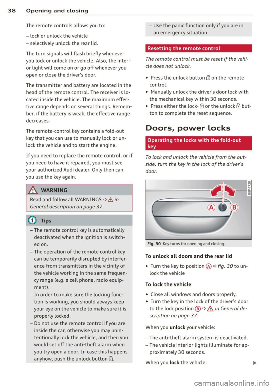
To lock and unlock the vehicle from the out
side, turn the key in the lo ck of the driver 's
door .
Fig. 30 Key turns for openi ng and closing.
To unlock all door s and the rear lid
.. Turn the key to position @ c> fig. 30 to un-
lock the vehicle
To lock the vehicle
,.. Close a ll win dows and doors pro perly.
.. Turn the key in the lock of the d river's door
to the loc k pos it ion
@ c> A in General de
scription on page 3
7.
When you unlock yo ur vehicle:
- The ant i-theft alarm system is dea ctivated.
- The vehicle i nterior lights illum inate fo r ap-
proximately 30 seconds .
When you
lock the vehicle:
Page 49 of 280
Clear vision Lights
· r/.· Switching the headlights on and off
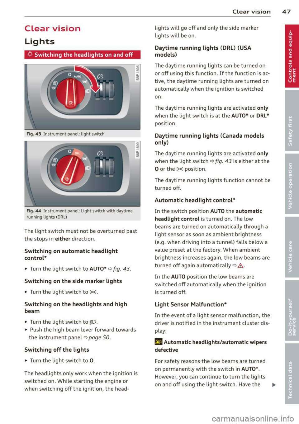
F ig. 4 3 In str ume nt pa ne l: light switch
F ig. 44 Instrumen t pane l: Light sw itch with dayt ime
running lights (DRL)
The ligh t sw itch must not be ove rtu rn ed past
the s tops in
either d ire ct io n.
Switching on automatic headlight
control*
.,. Turn the light swi tch to AUTO* ¢ fig. 43.
Switching on the side ma rker lights
.,. Turn the light switch to ooo=.
Switching on the headlights and high
beam
.,. Turn the light switch to tD .
.,. Pus h the high beam lever forward towards
the instrument pane l
Q page 50.
Switching off the lights
.,. Turn the light swi tc h to 0 .
The headlig hts on ly wo rk whe n the igni tion is
sw itche d on . W hile s tartin g the e ng ine or
when swit ching
off the ign ition , th e head-
Clear vision 4 7
lig hts w ill go off and only the side ma rke r
li ghts wi ll be on.
Daytime running lights (DRL) (USA
models)
The d aytime r unning lights can be tur ned on
o r
off using t his fu nction . If the function is ac
tive, the dayt ime ru nning lights a re turned on
a utomat ica lly when the ign ition is switched
o n.
T he daytime r unning lights are activate d
only
when the light switc h is at the AUTO* or DRL *
pos ition.
Daytime running lights (Canada models
only)
The daytime r unning lights are activated only
whe n the light switc h ¢ fig. 43 is either at the
0 or the coo: pos ition.
T he daytime r unning lights funct io n can not be
turned
off .
Automatic headlight control*
In the swi tch positi on AUTO the automatic
headlight control
i s tur ned on. The l ow
beams are turne d on au tomatically through a
li ght se nsor as soo n as amb ient brightness
(e .g. when dr iv ing into a t unnel) fa lls below a
val ue p reset at t he factory. Whe n ambient
bri ghtness i ncreases aga in, the low beams are
turned
off aga in a utomat ica lly c:> & .
In the AUTO position the low beams are
switc hed
off automatically when the ignition
is tur ned
off.
Light Sensor Malfunction*
In the event of a light se nsor malfunction, the
drive r is notifie d in the instrument cluste r dis
play:
ral Automatic headlights/automatic wipers
defective
Fo r sa fety reaso ns the low beam s are turned
on perm anen tly wi th the switch in
AUTO* .
However, you can co nti nu e to turn the lights
o n and
off u sing the lig ht switch. Have t he ..,.
Page 87 of 280
conditioner automatically se lects the settings
assigned to that key. This way every driver will maintain his/her own persona l settings and
does not have to reset them manually.
(D Tips
If a d ifferent driver uses your key and
changes the air conditioner settings, the
latest adjustments w ill erase and rep lace
the settings you have stored.
mP Rear window defogger
T he rear window defogger clears the rear win
dow of conden sation .
Fig. 98 Swi tch for rea r wi ndow defogger w ith a ir -con ·
d it io nin g
.. Press the QiP switc h to switch the rear win-
dow defogger on and off.
The defogger works on ly with the engine run
n ing. When the defogger is switched on, an
indicator light in the switc h comes on.
The rear w indow defogger switches
off au to
matica lly afte r abo ut 20 m inutes.
@ For the sake of the environment
T ur n the defogger off when the rea r win
dow is clear. When you save elec tricity, you
save fuel.
Additional heater
Applies to vehicles: with diesel engine
.. Switc h the Additional heate r to AUTO .
Vehicles w it h diese l eng ine s are equipped
with an add it ional heate r to warm the interior
of the vehicle mo re q uick ly. The additional
W arm and cold 85
heater switches itse lf on and off automatically
when the o utside temperature is below 50 °F
(10 °C) and the engine is running, depending
o n the coolant temperature , interior tempera
ture and the selected temperature.
Electrically heated
front seats
Applies to vehicles: with electrically heated front seats
With the ignition on , the seat cushion and
backrest of the front seats can be heated.
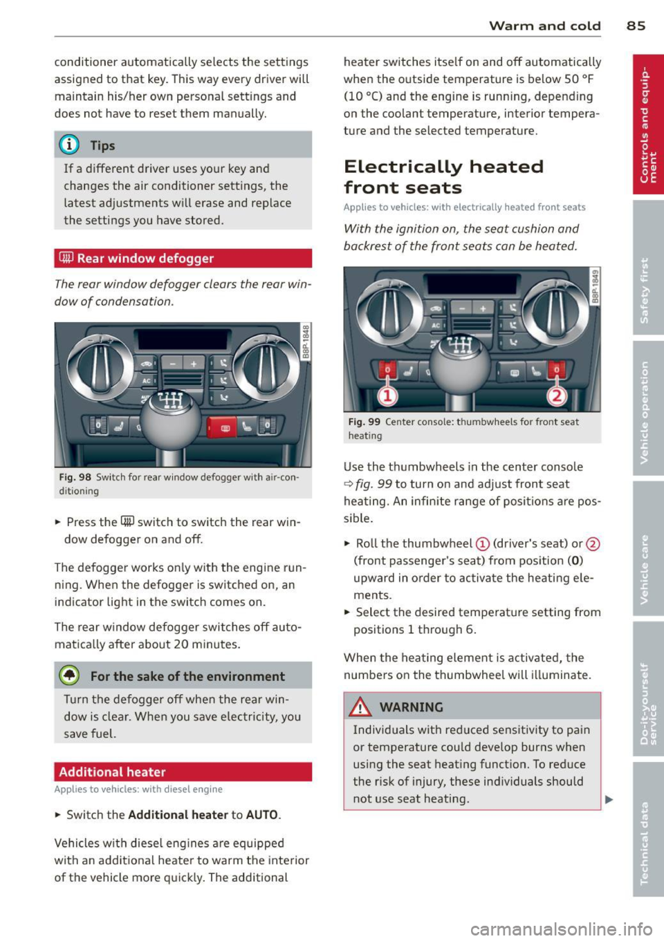
F ig . 99 Ce nter co nsole: t hu m bwhee ls for front seat
h eat ing
Use the t humbwheels in the center conso le
c;:> fig . 99 to turn on and adjust front seat
heating. An infin ite range of positions are pos
sible .
.. Ro ll t he thumbw heel
(D (dr iver's seat) or@
(front passenger's seat) from pos ition
( 0 )
upward in order to activa te the heati ng e le
ments .
.. Select the desired temperat ure setting from
positions 1 t hrough 6.
When the hea ting element is activated, the
numbers on the thumbwheel will illuminate .
& WARNING
Individuals wit h reduced sensitiv ity to pai n
or temperature cou ld deve lop burns when
using the seat heating funct ion. To reduce
the r isk of injury, these ind ividuals should
not use seat heating .
Page 97 of 280
Presetting your speed
You can preset your desired speed while the
vehicle is not moving .
.,. Turn on the ignition.
.,. Pull lever into position ©
c:> page 94,
fig . 105 .
"" Press the lever in the 0 or O direction to
increase or decrease yo ur speed .
.,. Re lease the lever to save that speed.
This function makes it possible, for example,
to save the speed you want before driving on
the highway . Once on the highway, activate
the cruise control by pulling the leve r toward
® ·
Switching the system off
Temporary deactivation
.,. Press the brake pedal, or
.,. Keep the clutch pedal pressed down
longer,
or
.,. Press the lever into pos ition @ (not clicked
into place)
c:> page 94, fig. 105, or
.,. Drive for longer than 5 minutes at more
than 5 mph (10 km/h) above the stored
speed.
Switching off completely
.,. Press lever into position@(clicked into
place), or
.,. Switch the ign ition off .
The system retains the saved speed if you de activate the cruise control temporarily. To re
sume the saved speed, release the brake or
clutch pedal and pull the lever to position
(D.
Switching the ignition off erases the saved
speed.
A WARNING
You should only return to the saved speed
if it is not too fast for the current traffic
conditions -risk of an accident!
On the road 95
Audi magnetic ride
Applies to vehicles: with magnetic ride
Damping can be adjusted to the driver's pref
erence and it adapts automatically to the cur
rent driving situation .
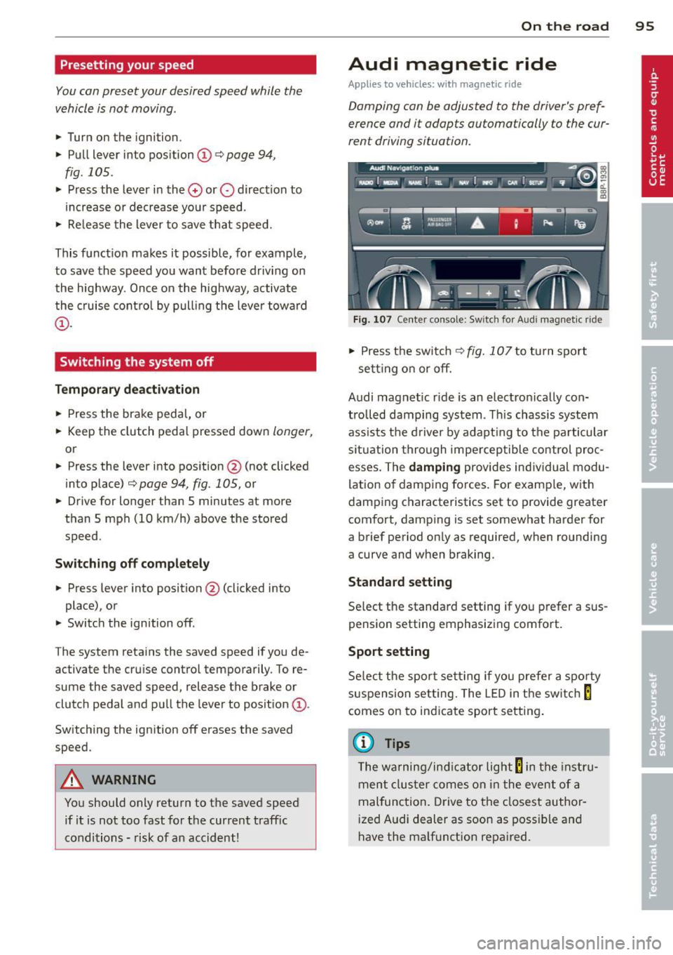
Fig. 107 Center console: Sw itch for Aud i magnet ic ride
.,. Press the switch c:> fig. 10 7 to turn sport
sett ing on or off.
Audi magnet ic r ide is an electronically con
trolled damping system . This chassis system
ass ists the driver by adapting to the particular
s ituat ion through imperceptible control proc
esses. The
damping provides individual modu
lation of damping forces. For example, with
damping characteristics set to provide greater
comfort, damping is set somewhat harder for
a brief period on ly as required, when rounding
a curve and when braking.
Standard setting
Select the standard setting if you prefer a sus
pension setting emphasizing comfort.
Sport setting
Select the sport setting if you prefer a sporty
suspension setting. The L ED in the switch
E
comes on to ind icate sport setting .
(D Tips
The warning/indicator light E in the instr u
ment cluster comes on in the event of a
malfunction. Drive to the closest author
i zed Audi dealer as soon as possible and
have the ma lfunction repa ired.
Page 233 of 280

remain continuously illuminated. This se
quence will continue upon subsequent vehicle
start-ups as long as the malfunction exists.
When the malfunction indicator is illuminat
ed, the system may not be able to detect or
signal low tire pressure as intended . TPMS
malfunct ions may occur for a variety of rea
sons, including the installation of replace
ment or alternate tires or wheels on the vehi
cle that prevent the TPMS from functioning
properly . Always check the TPMS malfunction
tellta le after replacing one or more tires or
wheels on your vehicle to ensure that the re
placement or alternate tires and wheels allow
the TPMS to continue to function properly.
Tire pressure indicator appears
Appl ies to vehicles: with tire pressur e monitoring sys te m
The tire pressure indicator in the instrument
cluster informs you if the tire pressure is too
low or if there is a system malfunction.
Fig. 172 Display : underinflation warning
Fig. 173 Display: System malfunction
Using the ABS sensors, the tire pressure moni
toring system compares the tire tread circum
ference and vibration characteristics of the in
dividual tires. If the pressure decreases in one
or more tires, this is indicated in the instru
ment cluster with a warning symbol
ti] and a
Tires and wheels 231
message r=!) fig. 172. The driver message in the
display goes out after 5 seconds. The driver
message can be displayed again by pressing
the
ICHECKI button @¢ page 10, fig . 3 . If on
ly one tire is affected, the display will indicate
its position .
The tire pressure monitoring must be reset in
the menu display each time the pressures are
adjusted (e .g. when switching between parti
al and full load pressure) or after changing or
replacing a tire on your vehicle¢
page 232.
You can find the recommended tire pressures
for your vehicle on the label on the driver's
door pillar¢
page 216.
Tire tread circumference and vibration charac
teristics can change and cause a tire pressure
warning if:
- the tire pressure in one or more tires is too
low,
- the tire has structural damage,
- the tire pressure was changed, wheels rotat- ed or replaced but the TPMS was not reset
¢page 232.
Warning symbols
ti] Loss of pressure in at least one tire¢&.
Check the tire or tires and replace or repair if
necessary. The indicator light
ti] in the instru
ment cluster also illuminates
¢page 13.
Check/correct the pressures of all four tires
and reset TPMS in the menu display .
11@1&1 (Tire Pressure Monitoring System) Tire
pressure! System malfunction . Ifll@IS, ap
pears after switching the ignition on or while
driving ¢
fig. 173 and the indicator light ti] in
the instrument cluster blinks for approx i
mately one minute and then stays on, there is
a system malfunction. See your autho rized
Audi dealer as soon as possible.
A WARNING
-If the tire pressure indicator appears in
the instrument cluster display, one or
more of your tires is significantly under
inflated. Reduce your speed immediately
and avoid any hard steering or braking ..,.
Page 234 of 280

232 Tires and wheels
maneuvers. Stop as soon as possible and
check the tires and their pressures. In
flate the tire pressure to the proper pres
sure as indicated on the vehicle's tire
pressure label ¢
page 216. Driving on a
significantly under-inf lated tire causes
the tire to overheat and can lead to tire
failure. Under-inflation also is likely to
impair the vehicle's handling and stop
ping ability.
- T he driver is responsible for maintain ing
the correct tire pressures. You must
check the tire pressures regularly.
- Under certain cond itions (such as a spor
ty driving style, winter conditions or un
paved roads), the pressure monitor indi
cator may be delayed.
- Ask your authorized Audi dealer if run
flat tires may be used on your vehicle .
Your vehicle registration becomes invalid
if you use these tires when not permit
ted. Damage to your veh icle or acc idents
could also result .
(D Tips
- The tire pressure monitoring system
stops working when there is an ESP/ABS malfunction .
- Using snow chains may result in a system
malfunction.
- Tires with the identification "AO" or "RO"
have been specially matched with your
Audi. We recommend using only these
tires because they meet the highest
standards regarding safety and driving
characteristics when used correctly. Your
a uthorized Audi dea ler will g ladly pro
v ide you w ith more information.
Reset tire pressure monitoring system
(Stepl)
Applies to veh icles: w ith tire pressure monitoring system
If the tire pressure is adjusted, wheels ore ro
tated or changed, the TPMS must be reset in
the menu display.
----- ®
Fig. 174 Wipe r lever: Contro ls fo r the menu d isplay
Fig. 175 Disp lay: S ta rt m enu
I Rese t I button @ and rocker switch @
¢ fig. 17 4 functions:
To open the menu
" Press the I Reset ! button @ unt il the menu
disp lay¢
fig. 175 appears
Selections and settings
" Press the rocker switch @ to reach a menu
d isp lay. The switch is operated the same as
the display (up/down) .
Entering and confirming
" Press the I Reset I button @.
Returning to the Start menu
" Press the I Rese t I button longer than 2 sec
onds to return from any menu level to the
Start menu.
Page 235 of 280

@ Tips
-Before resetting the TPMS, the current
pressures of
all four tires must corre
spond t o the specified va lues. Adjust the
tire pressu re and reset the pressure in
the tire pressure mon itor ing system ac
cord ing to the load yo u are carry ing
~pag e
216.
- Do not store the tire pressures if snow
cha ins a re installed. Otherw ise the sys
tem could malfunction.
Reset tire pressure monitoring system
(Step2}
Applies to vehicles: with tire pressure monitoring system
Fig. 1 76 Display: Tire pressure
Fig. 1 77 Display: Tire pressure
I Reset ! button @ and rock e r swit ch @
~ page 232, fig . 17 4 func tions:
Storing tire pressures
.. Turn on the ignition .
.. Se lect the menu:
> Adjusting * > Tire pres-
sure
> Store .
Entering and confirming
.. Se lect the menu : Store now
.. Press the
I Reset I button @ .
.. Se lect the menu : Confirm
Tires and wheels 233
.. Press the I Reset I button @.
Returning to the Start menu
.. Press the I Reset ! button longer than 2 sec
onds to re tur n from any menu level to the
S ta rt men u.
{!) Tips
Befo re resetting the TPMS, t he cur rent
p re ssu res of
all four tires mus t corres pond
to the speci fied val ues. Adjus t the tire
pr essure and rese t the pressure in the ti re
press ure monitoring system acco rding to
the load you are carry ing
~ page 216 .
Page 246 of 280
244 Fuses and bulbs
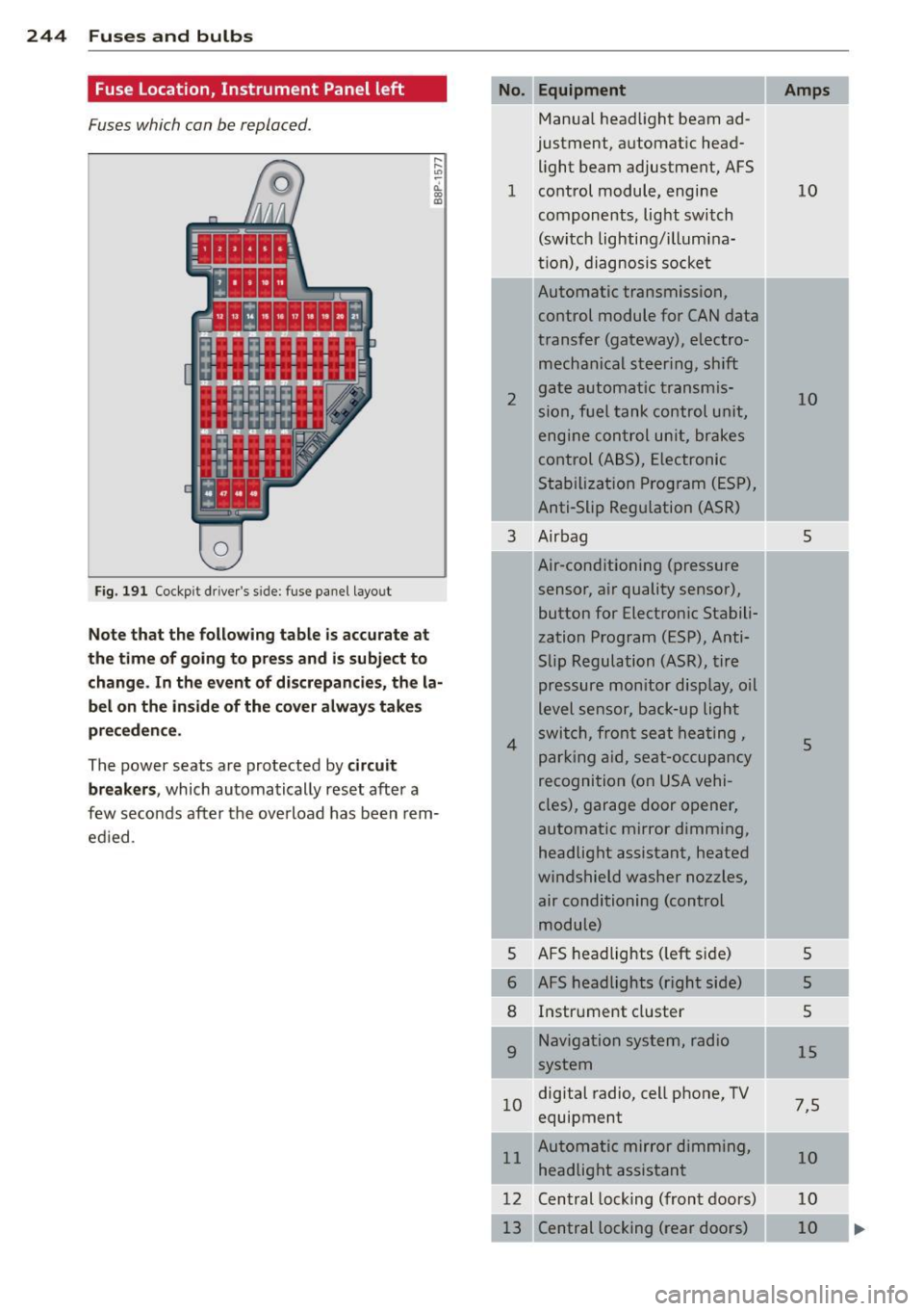
Fuse Location, Instrument Panel left
Fuses which can be replaced.
Fig. 191 Cockp it driver 's s ide: fuse pane l layout
Note that the following table is accurate at
the time of going to pr ess and i s subject to
change . In the event of d iscrepancies, the la
bel on the in side of the cover always take s
pr eceden ce .
The power seats are protected by circuit
break ers,
which automatically reset after a
few seconds after the ove rload has been rem
ed ied .
Equipment
Manua l head light beam ad
justment, a utomat ic head
light beam adjustment, AFS
1 co ntrol m odule, engine
components, light switch
(switch lighting/illumina
ti on), diagnosis socke t
2
3
4
5
6
8
9
Automatic transmission,
control module for CAN data
transfer (gateway), electro
mechanical steering, shift
gate automatic transmis
sion, fuel tank control unit,
engine control unit, brakes
control (A BS), Electronic
Stabili zation Program (ESP) ,
Anti-Slip Regulation (ASR)
Air bag
Air-conditioning (pressure
sensor, air quality sensor), button for Electronic Stabili
zation Program (ESP), Anti
Slip Regulat ion
(ASR), tire
pressure monitor display, oil
level senso r, back-up ligh t
s w itch, front se at he ati ng ,
p ark ing aid, sea t-occupancy
recognition (on USA vehi
cles), garage door opener,
automa tic mirror dimming,
headlight assistant, heated
windshield washer nozzles, air conditioning (control
module)
AFS headlights ( left si de)
AFS headlights (right side) Instr ument cluster
Navigation system, radio
system
1 0 digital
radio, cell phone, TV
equipment
11 Automatic mirror dimming,
headlight assistant
12 Central lock ing (front doors)
Central locking ( rear doors)
Amps
10
10
5
5
5
5
5
15
7 ,5
10
10
10
Page 247 of 280
No. Equ ipment
Electronic Stabilization Pro-
14
gram (ESP) (control mod-
u le), shift gate automatic
transmission
15 Interior lights, reading
lights
Diagnostic connector, rain
sensor, air conditioning
16 (control module), t
ire pres-
sure monitor d isplay (con-
trol module)
I 17
Anti-theft alarm warning
system
18 D iagnose Starter
19 All Wheel D rive
20 Audi magnetic ride
Blower fan
23
Driver's
side power window,
front
24 Power outlet front
2S Rear window defogger
26 Power outlet in luggage
compartment
27 Fuel tank control module,
fuel pump
28 Power window, rear
33 Slidi ng/pop-up roof
36 Lumbar support
37 Heated sea ts, front
1 38
Passenger side power win-
dow, front
39 Specia l func tion interface
40 Starter
41 Rear window wiper
43 Body control module
47
Ce ll phone package (V OA in-
terface)
Automatic circuit breakers:
10
10
10
5
5
10
40
30
20
30
20
15
30
20 10
20
30
5
40
15
20 5
The electri c power w in dows and the e lectr ic
seat adjusters are pro tected with circu it
breake rs which reset automatically after the
circuit overload has been corrected.
Fu se s and bulb s 245
@ Tips
-Whenever rep lacing a fuse, always con
sult the sticker on the inside of the f use
pane l cover. It contains the most up-to
date information regarding the fuse ar
rangement. If in doubt, ask your author
ized Aud i Service adviso r.
- Some of the equipment items listed are
opt ional or only available on certa in
mode l configurations.
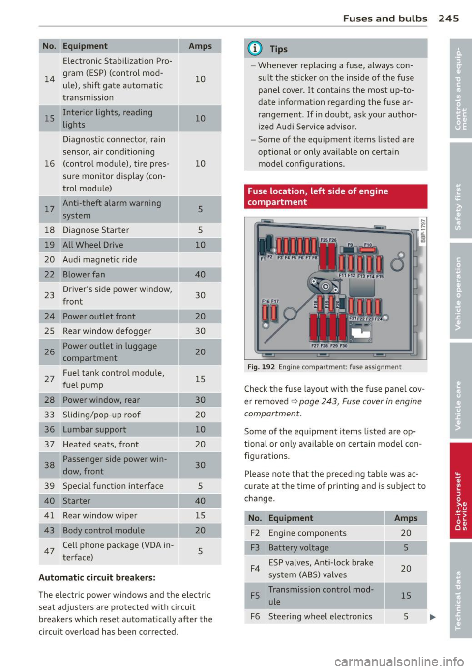
Fuse location, left side of engine
compartment
Fig . 192 En gine compar tment : fuse assig nment
,._
-d. a, a>
Check the fuse layout with the f use panel cov
er removed
¢ page 243, Fuse cover in engine
comportment.
Some of the equipmen t items listed are op
tiona l or only ava ilab le on certain model con
figurations.
Please note tha t the preced ing tab le was ac
c u rate at the time of pr int ing and is subject to
c h ange.
No. Equipment
F2 Engine compone nts
F3 Battery voltage ESP valves, Anti-lock brake
F4 system (ABS) valves
Transmission control mod
F5 ule
F6 Steering wheel e lectronics
Amps
20
5
20
15
s