engine AUDI A3 2020 Owner´s Manual
[x] Cancel search | Manufacturer: AUDI, Model Year: 2020, Model line: A3, Model: AUDI A3 2020Pages: 400, PDF Size: 107.47 MB
Page 3 of 400
8V2012721BK
Foreword
Thank you for choosing an Audi - we value your trust in us.
Your new Audi will allow you to experience the best in groundbreaking technology and premium quality
equipment that a vehicle has to offer. We recommend that you read your Owner's Manual thoroughly
so that you quickly become acquainted with your Audi and make use of all of its features.
In addition to explaining how the different features work, we provide many useful tips and information
concerning your safety, how to care for your vehicle, and how to maintain your vehicle's value. We also
give you useful tips and information on how to drive your vehicle more efficiently and in an environ-
mentally-friendly manner.
We hope you enjoy driving your Audi and we wish you safe and pleasant motoring.
AUDI AG
A WARNING
Operating, servicing and maintaining a passenger vehicle or
off-highway motor vehicle can expose you to chemicals includ-
ing engine exhaust, carbon monoxide, phthalates, and lead,
which are known to the State of California to cause cancer and
birth defects or other reproductive harm. To minimize expo-
sure, avoid breathing exhaust, do not idle the engine except as
necessary, service your vehicle in a well-ventilated area and
wear gloves or wash your hands frequently when servicing
your vehicle. For more information go to www.P65Warnings.
ca.gov/passenger-vehicle.
Page 6 of 400
Table of contents
Audi smartphone interface...... 228
Setup... eee eee ee eee 228
OPeratintg’s + ease s x mows « woeE se ow ee 229
Troubleshooting wwii «s wwine ev eee ae eae 229
System settings.................. 230
Setting the date andtime............. 230
MMI SOMOS: » sunses 0 » anexeiae o anseane » 0 exons 230
Connection manager................. 231
System update isis ss wows x ¢ seows a eaves 234
Sound settingS............0 ee eee eee 234
Volume settings ..............000000. 234
Restarting the MMI.................. 235
Software license information.......... 235
237 237 237
Correct passenger seating positions..... 238
Driver's and front passenger's footwell.. 241
Pedal area.......... eee eee eee eee 241
Active rollover protection system....... 242
Safety belts...................0.. 245
General notes.................00005. 245
Why use safety belts?................ 246
Safety belts. ............... 00000005 248
Belt tensioners... 0.02... cece eee eee 252
Airbag system.................00. 253
Important information............... 253
Front:airbags’: = seis s = canes + = esis + oer 257
Monitoring the Advanced Airbag System. 265
Knee airbags...............-0 ee eee 269
Side@:airbags x: < sews se eewes te eee ee oe 271
Sidercurtain airbags « swe ss wei sv woes 274
GAUGES AATEC iss 5 « nee a 5 Baa GE EE Be 278
Important information............... 278
Child safety seats................000. 284
Securing child safety seats............ 289
LATCH system (lower anchorages and
tethers forichildren) sic. o = essere x 3 awmin « 5 aoe 292
Additional information............... 297
Maintenance and Care........... 298
Checking and Filling............. 298
FUGlaves: «2 wows s 2 seems © a meee 4 S oweme a 2 a 298
Reftieling crass « sccswes e neness xe aeiceme x acer 299
Refueling ......... 0... cee ee eee eee 302
Emissions control system............. 303
Engine compartment...........0.500% 304
Engineoil........ 0... eee eee eee 307
Cooling SYSteM . <= sees ic sees be tees we 311
Brake Pluidhise «2 ascii 2 2 soos 2 x comes © x sree 313
Electrical system. ...........002-000 314
Battenysa « 5 news so ASS & ROS TE BaF 315
Windshield washer system............ 317
Service interval display............... 318
Whe6US: « ses ss sess os ees ss eee 2 a 319
Wheelsiand Tiresis « scsinin + « sore © a eneron » 319
Tire Pressure Monitoring System indicator . 337
Tire pressure monitoring system....... 339
Care and cleaning................ 342
General information................. 342
Gar washesi: « sosus so ime a 0 mana + omen 6 342
Cleaning and care information......... 343
Taking your vehicle out of service....... 347
Troubleshooting................. 348
Emergency assistance........... 348
Trunk escape latch............-.0000- 348
General
information................. 348
Equipment............. 00. cece eee 348
Tire Mobility kit’: goss « 2 sewn 2 y eweE a eos 349
Replacing wheels...........00ee eens 352
Sparetire........ 2... eee eee eee 357
Fuses and bulbs.................. 360
FUSES 2... eee ete eee 360
BULDS-
General...............0. 0000 cece 364
Starting by pushing or towing.......... 364
JUIMPESTAREIIG . « suerns 6 & sasnnes » « sanree wo samme 364
Towing with atowtruck............... 367
Raising the vehicle.................-. 369
Page 11 of 400
8V2012721BK
Quick access
Door handle
SIdG-ASSISE « = = ems 5 = saws 5 2 owE «
Central locking switch ...........
Lighteswiteh ccs xo seers oo ewenens « «0
VENUS! « vases 5 cee 2 o Hee © © ew
Lever for: ©OOOCOO
—Turn signals and high beams ....
— High beam assistant ..........
— Active lane assist .............
9 Multifunction steering wheel with:
— Horn be
—Driver's airbag ...............
— Driver information system con-
FENOUS) oo secrece + a sasmeie «3 smote = ome
— Audio/video, telephone, naviga-
tion, and voice recognition con-
EOUS! © 2 secs 2 awsenw 2 8 somes 3 3 veses
— Button [*|/steering wheel heating .
— Shift paddles ................
Instrument cluster .............
Windshield washer system lever ..
O©®@ Steering column, with the follow-
ing, depending on equipment:
IQMitiom lock: « s seis « svinne 0 seme
— Starting the engine when there is
amalfunction ................
Adjustable steering column ......
Lever for: ®®
— Cruise control system .........
— Adaptive cruise control ........
Knee airbag ......... cee eee ae
Instrument illumination .........
Hood release? s « swas s emew se ews
Data link connector for On Board
Diagnostic System (OBDII) ......
Switch (depending on the equip-
ment) for:
©
OO88O®@
— Luggage compartment lid ......
— Fuel filler door (plug-in hybrid
CriVe) ws 2 2 wee s y cous ye eee oe
Power exterior mirror adjustment .
Power windows ...............-
©O® Depending on equipment:
—Child safety lock ..............
— Central power window switch ...
131
29
43
65
44 44
128
257
17, 20
19, 20
19, 20
76
14
49
72 73
58
115
118
269
47
305 371
31
302
47
33 33 33
@) Infotainment system display .....
@) Glove compartment ............
@3) Drives for CD, DVD, SIM cards ....
@) Front passenger's airbag ........
@3) Depending on equipment, buttons
for:
— Driveselect® scajs ss sues eo gees ee
— Start/Stop system ............
—|<"| button (plug-in hybrid drive) .
EParkcassist « « sss os sexes vo come
—Parkingaid ..................
—Emergency flashers ...........
— Electronic Stabilization Control
(ES©) wp < 2 ume = seeps = ome & ¥ ne
— Infotainment system display ....
— Front passenger airbag off indica-
EOI sansae +o: senses 4 «aimee « neues © ese
@8 Deluxe automatic climate control .
@) Socket ..............02. 220
@8) Selector lever (automatic transmis-
(0) 1)
@) Cupholders ..............0000-
G0 Infotainment system on/off button .
@) Infotainment unit ..............
@ Power top operation ............
63. Center armrest with storage com-
partment. Depending on vehicle
equipment, it may have:
— Audi music interface ..........
— Audi smartphone interface .....
—Audi phone box ...............
G4 Electromechanical parking brake . .
@) [START ENGINE STOP
G8 Audi music interface ............
G) Tips
147
212
257
91
83
79
140 137
45
93
147
265
66 59
75
59
146 146
36
217 228
171
87
71
217
Some the equipment listed here is only instal-
led in certain models or is available as an op-
tion.
Page 12 of 400
Quick access
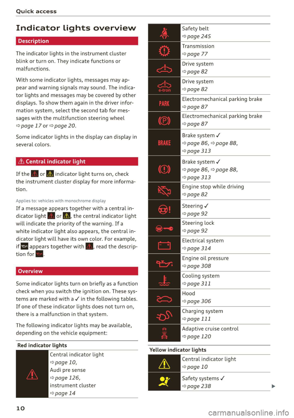
Indicator lights overview
The indicator lights in the instrument cluster
blink or turn on. They indicate functions or
malfunctions.
With some indicator lights, messages may ap-
pear and warning signals may sound. The indica-
tor lights and messages may be covered by other
displays. To show them again in the driver infor-
mation system, select the second tab for mes-
sages with the multifunction steering wheel
=> page 17 or > page 20.
Some indicator lights in the display can display in
several colors.
MMe O eel em lis
If the wa or MN indicator light turns on, check
the instrument cluster display for more informa-
tion.
Applies to: vehicles with monochrome display
If a message appears together with a central in-
dicator light A\ or A the central indicator light
will indicate the priority of the warning. Ifa
white indicator light also appears, the central in-
dicator light will have its own color. For example,
it appears together with Bw read the descrip-
tion for &.
Some indicator lights turn on briefly as a function
check when you switch the ignition on. These sys-
tems are marked with a V in the following tables.
If one of these indicator lights does not turn on,
there is a malfunction in that system.
The following indicator lights may be available,
depending on the vehicle equipment:
Red indicator lights
Central indicator light
=> page 10,
Audi pre sense
=> page 126,
instrument cluster
=> page 14
10
Safety belt
=> page 245
Transmission
> page 77
Drive system
=> page 82
Drive system
=> page 82
Electromechanical parking brake
=> page 87
Electromechanical parking brake
=> page 87
Brake system ¥
=> page 86, > page 88,
=> page 313
Brake system ¥
=> page 86, > page 88,
> page 313
Engine stop while driving
=> page 82
Steering ¥
=> page 92
Steering lock
=> page 92
Electrical system
=> page 314
Engine oil pressure
=> page 308
Cooling system
=> page 311
Hood
=> page 306
Charging system
> page 111
Adaptive cruise control
=> page 120
Yellow indicator lights
Central indicator light
=> page 10
Safety systems ¥
=> page 238
Page 13 of 400
8V2012721BK
Quick access
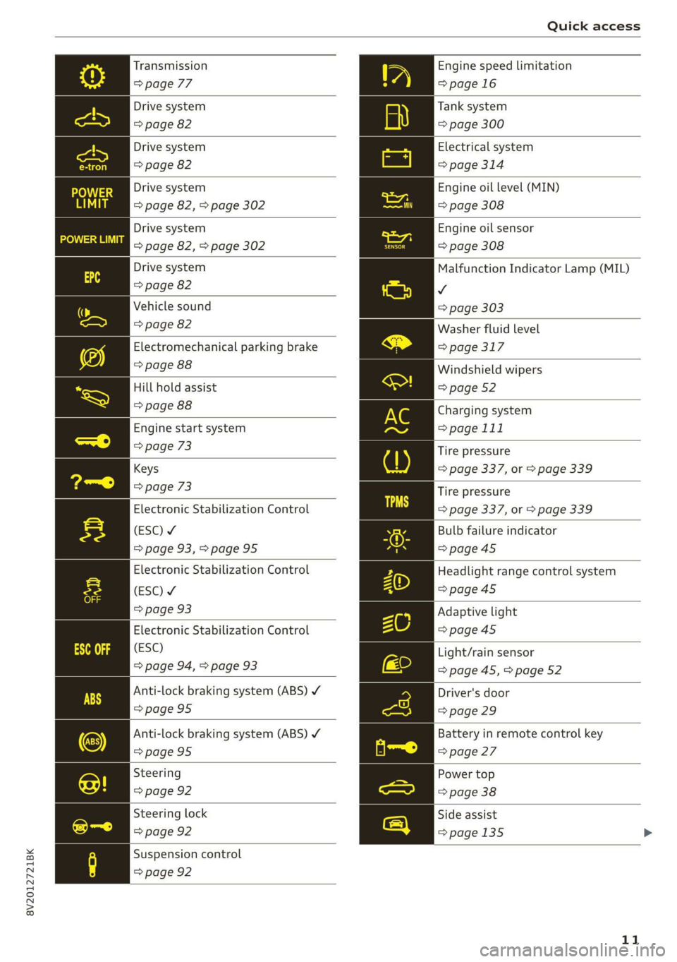
Transmission
=> page 77
Drive system
=> page 82
Drive system
=> page 82
Drive system
=> page 82, > page 302
Drive system
=> page 82, > page 302
Drive system
=> page 82
Vehicle sound
=> page 82
Electromechanical parking brake
=> page 88
Hill hold assist
=> page 88
Engine start system
=> page 73
Keys
=> page 73
Electronic Stabilization Control
(ESC) ¥
=> page 93,>page 95
Electronic Stabilization Control
(ESC) ¥
=> page 93
Electronic Stabilization Control
(ESC)
=> page 94, > page 93
Anti-lock braking system (ABS) ¥
=>page 95
Anti-lock braking system (ABS) Y
=> page 95
Steering
=> page 92
Steering lock
=> page 92
Suspension control
=> page 92
Engine speed limitation
=>page 16
Tank system
=> page 300
Electrical system
=> page 314
Engine oil level (MIN)
=> page 308
Engine oil sensor
=> page 308
Malfunction Indicator Lamp (MIL)
v
=> page 303
Washer fluid level
=> page 317
Windshield wipers
=> page 52
Charging system
=> page 111
Tire pressure
=> page 337, or > page 339
Tire pressure
=> page 337, or > page 339
Bulb failure indicator
=> page 45
Headlight range control system
=>page 45
Adaptive light
=>page 45
Light/rain sensor
=> page 45, > page 52
Driver's door
=> page 29
Battery in remote control key
=> page 27
Power top
=> page 38
Side assist
=>page 135
11
Page 14 of 400
Quick access
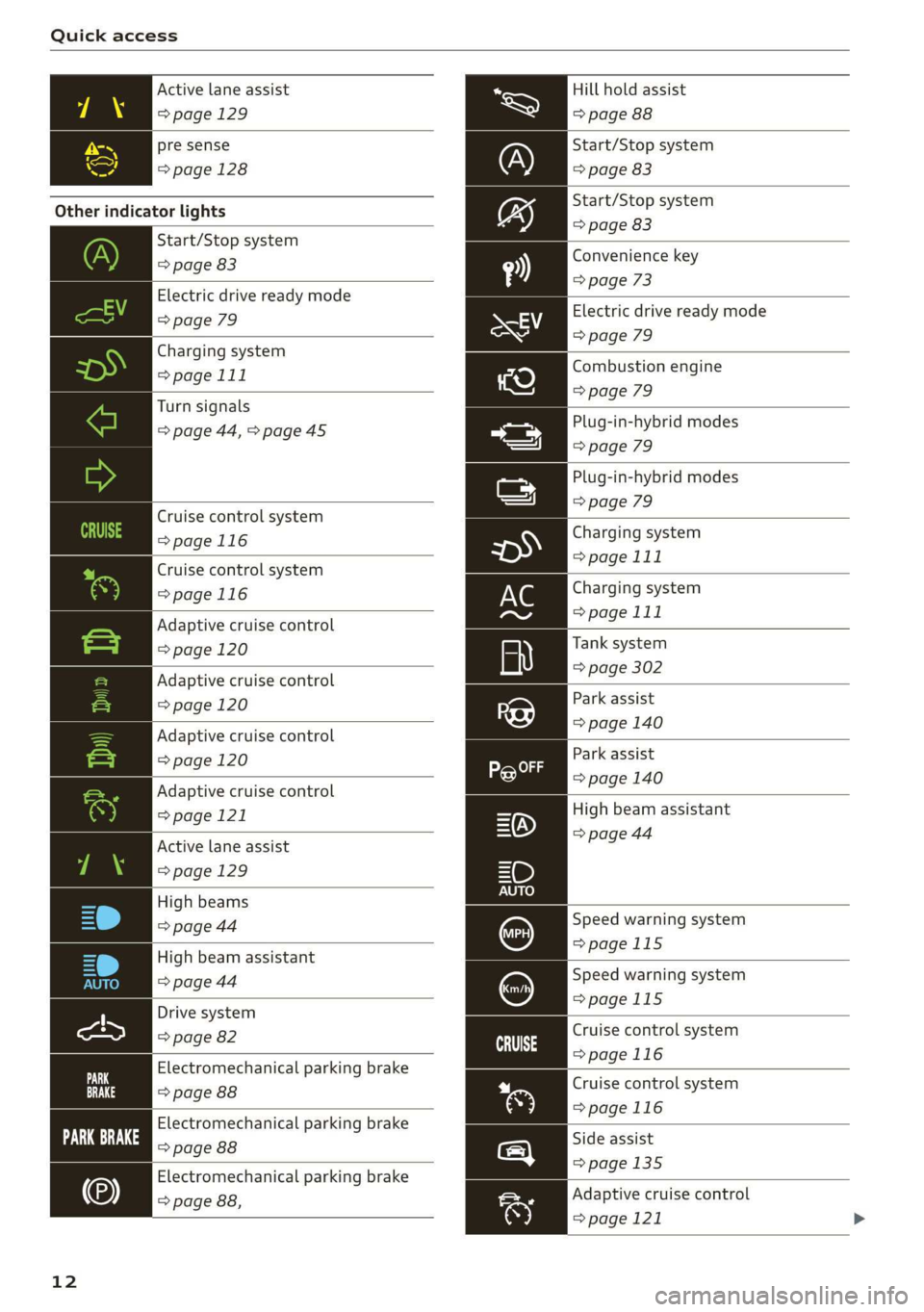
Active lane assist
=> page 129
pre sense
=>page 128
Other indicator lights
Start/Stop system
=> page 83
Electric drive ready mode
=> page 79
Charging system
=> page 111
Turn signals
=> page 44, > page 45
Cruise control system
=>page 116
Cruise control system
=>page
116
Adaptive cruise control
=> page 120
Adaptive cruise control
=> page 120
Adaptive cruise control
=> page 120
Adaptive cruise control
=> page 121
Active lane assist
=> page 129
High beams
=> page 44
High beam assistant
=> page 44
Drive system
=> page 82
Electromechanical parking brake
=> page 88
Electromechanical parking brake
Fe ove ae
Electromechanical parking brake
=> page 88,
12
Hill hold assist
=> page 88
Start/Stop system
=> page 83
Start/Stop system
=> page 83
Convenience key
=> page 73
Electric drive ready mode
=> page 79
Combustion engine
=> page 79
Plug-in-hybrid modes
=> page 79
Plug-in-hybrid modes
=> page 79
Charging system
=> page 111
Charging system
=> page 111
Tank system
=> page 302
Park assist
=> page 140
Park assist
=> page 140
High beam assistant
=> page 44
Speed warning system
=>page 115
Speed warning system
=>page 115
Cruise control system
>page 116
Cruise control system
>page 116
Side assist
=>page 135
Adaptive cruise control
=> page 121
Page 16 of 400
![AUDI A3 2020 Owner´s Manual Instrument cluster
Instrument cluster overview
The instrument cluster is the central information center for the driver.
| B8U-0400]
CHLOE
a YLY plese)
E ‘
Applies to: vehicles with Aud AUDI A3 2020 Owner´s Manual Instrument cluster
Instrument cluster overview
The instrument cluster is the central information center for the driver.
| B8U-0400]
CHLOE
a YLY plese)
E ‘
Applies to: vehicles with Aud](/img/6/40265/w960_40265-15.png)
Instrument cluster
Instrument cluster overview
The instrument cluster is the central information center for the driver.
| B8U-0400]
CHLOE
a YLY plese)
E ‘
Applies to: vehicles with Audi virtual cockpit
Fig. 3 Instrument cluster overview
[e8u-0399]
Applies to: vehicles with analog instrument cluster
Fig. 4 Instrument cluster overview
Depending on the vehicle equipment, the follow- ) Status line (one or two lines)
ing items may appear in the instrument cluster: © Trip odometer reset button ...... 17
@ Display @ Right dial
— Engine coolant temperature
— High-voltage battery charge level 8) Display
@ Left dial —Fuellevel MY .............000. 300
—Tachometer ................- 15 Q) Right additional display with speed-
— Power meter ................2. 16 ometer
3 17,20 Left additional display with:
17, 20
14
Page 17 of 400
8V2012721BK
Instrument cluster
SSGOAM’ sx cscsone ov cxexens @ a aomnees vo s8sue 75
— Audi drive select mode ......... 91
ZA WARNING
Applies to: vehicles with Audi virtual cockpit
If there is a severe malfunction in the instru-
ment cluster, the display may turn off. The wa
indicator light may also turn on. Stop the ve-
hicle safely. See an authorized Audi dealer or
authorized Audi Service Facility for assistance.
@ Tips
— The following pages will primarily show il-
lustrations of the multi-color analog instru-
ment cluster*. The display and/or position
of the element shown may vary in mono-
chrome instrument clusters or in the Audi
virtual cockpit*.
— You can select the units used for tempera-
ture, speed, and other measurements in the
Infotainment system > page 230.
— Speeds are displayed in mph (miles per
hour) or km/h (kilometers per hour).
— If there is a malfunction in the instrument
cluster, DEF will appear in the trip odometer
display. Have the malfunction corrected as
soon as possible.
— Depending on vehicle equipment, the in-
strument illumination (needles and gauges)
may turn on when the lights are off and the
ignition is switched on. The illumination for
the gauges reduces automatically and even-
tually turns off as brightness outside in-
creases. This function reminds the driver to
turn the low beams on at the appropriate
time.
Coolant temperature
display
Applies to: vehicles with a coolant temperature indicator
The coolant temperature display @) > page 14
only functions when the ignition is switched on.
To reduce the risk of engine damage, please ob-
serve the following notes about the temperature
ranges.
Cold range
If only the LEDs at the bottom of the gauge turn
on, the engine has not reached operating tem-
perature yet. Avoid high engine speeds, full accel-
erating and heavy engine loads.
Normal range
The engine has reached its operating tempera-
ture once the LEDs up to the center of the gauge
turn on. If the || indicator light in the instru-
ment cluster display turns on, the coolant tem-
perature is too high > page 311.
@) Note
— Auxiliary headlights and other accessories in
front of the air intake impair the cooling ef-
fect of the coolant. This increases the risk of
the engine overheating during high outside
temperatures and heavy engine load.
—The front spoiler also helps to distribute
cooling air correctly while driving. If the
spoiler is damaged, the cooling effect will
be impaired and the risk of the engine over-
heating will increase. See an authorized
Audi dealer or authorized Audi Service Fa-
cility for assistance.
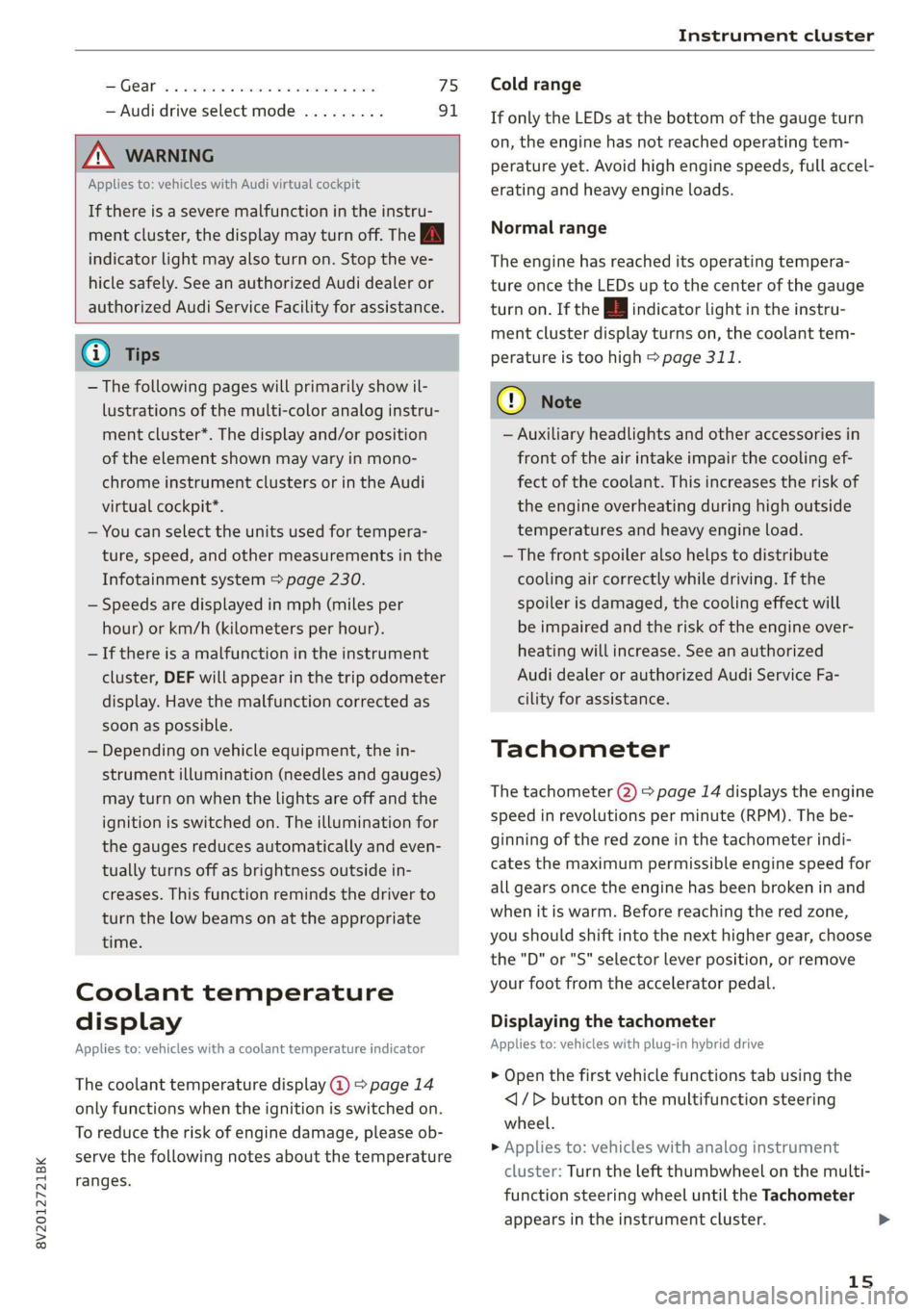
Tachometer
The tachometer (2) > page 14 displays the engine
speed in revolutions per minute (RPM). The be-
ginning of the red zone in the tachometer indi-
cates the maximum permissible engine speed for
all gears once the engine has been broken in and
when it is warm. Before reaching the red zone,
you should shift into the next higher gear, choose
the "D" or "S" selector lever position, or remove
your foot from the accelerator pedal.
Displaying the tachometer
Applies to: vehicles with plug-in hybrid drive
> Open the first vehicle functions tab using the
<1/D button on the multifunction steering
wheel.
> Applies to: vehicles with analog instrument
cluster: Turn the left thumbwheel on the multi-
function steering wheel until the Tachometer
appears in the instrument cluster.
15
>
Page 18 of 400
Instrument cluster
» Applies to: vehicles with Audi virtual cockpit:
Select on the multifunction steering wheel:
right control button > Left dial > Tachometer or
Combination view.
Engine speed limitation
Applies to: vehicles with engine speed limitation
If the BA indicator light turns on, the engine will
be automatically limited to the RPM displayed in
the instrument cluster. This will protect the en-
gine components, for example during a cold start
or from overheating.
The engine speed limitation deactivates once the
engine is no longer in the critical temperature
range and you have released the accelerator ped-
al once.
If the engine speed limitation was activated by
an engine control malfunction, the B or EPC | in-
dicator light also turns on. Make sure the engine
speed does not go above the speed displayed, for
example when downshifting. Drive to an author-
ized Audi dealer or authorized Audi Service Facili-
ty immediately to have the malfunction correct-
ed.
@ Note
The needle in the tachometer (2) may only be
in the red area of the gauge for a short period
of time before there is a risk of damaging the
engine. The location where the red zone be-
gins varies depending on the engine.
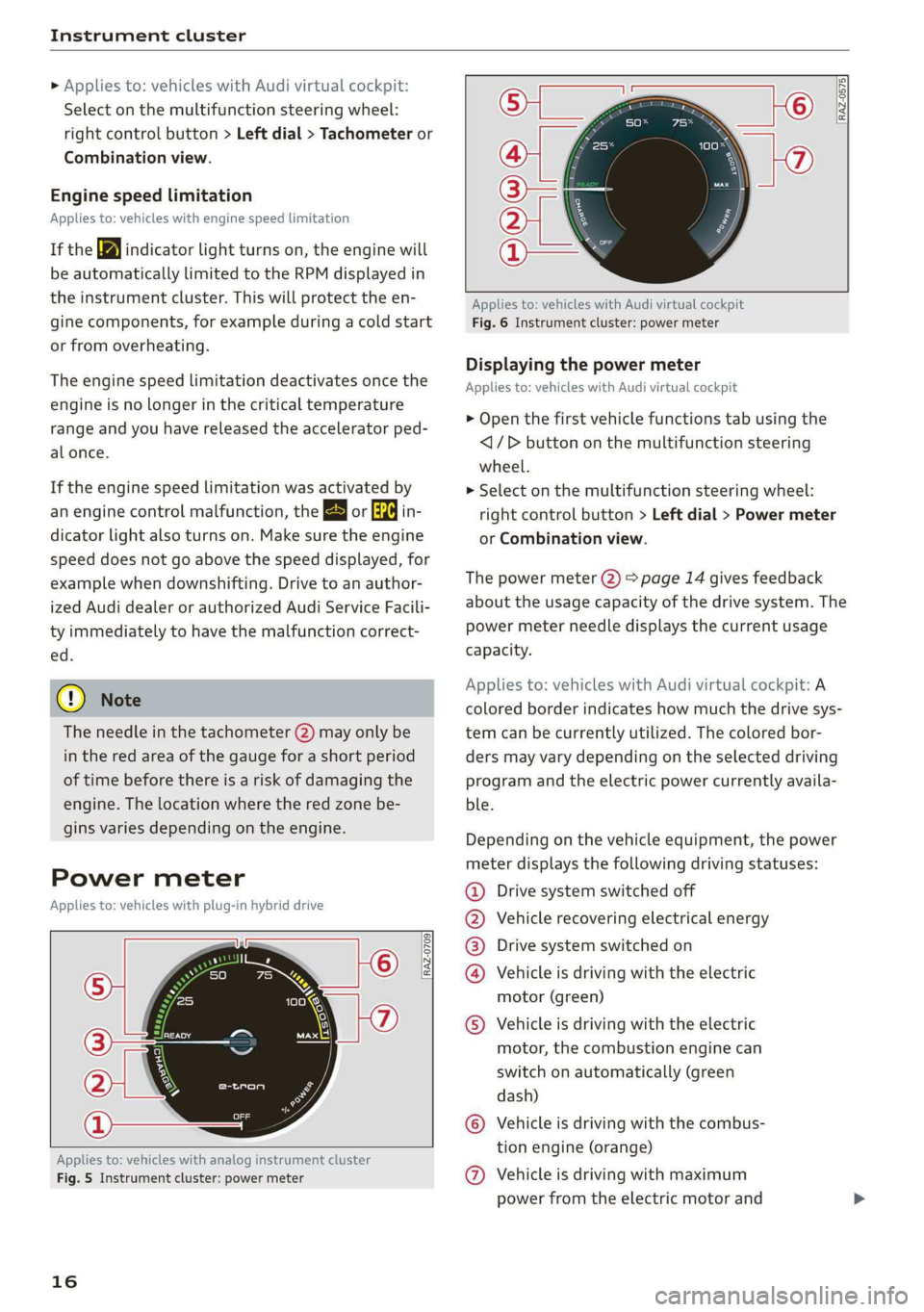
Power meter
Applies to: vehicles with plug-in hybrid drive
RAZ-0709
Applies to: vehicles with analog instrument cluster
Fig. 5 Instrument cluster: power meter
16
[RAZ-0575]
Applies to: vehicles with Audi virtual cockpit
Fig. 6 Instrument cluster: power meter
Displaying the power meter
Applies to: vehicles with Audi virtual cockpit
> Open the first vehicle functions tab using the
<1/D button on the multifunction steering
wheel.
> Select on the multifunction steering wheel:
right control button > Left dial > Power meter
or Combination view.
The power meter (2) > page 14 gives feedback
about the usage capacity of the drive system. The
power meter needle displays the current usage
capacity.
Applies to: vehicles with Audi virtual cockpit: A
colored border indicates how much the drive sys-
tem can be currently utilized. The colored bor-
ders may vary depending on the selected driving
program and the electric power currently availa-
ble.
Depending on the vehicle equipment, the power
meter displays the following driving statuses:
Drive system switched off
Vehicle recovering electrical energy
Drive system switched on
Vehicle is driving with the electric
motor (green)
©
©0800
Vehicle is driving with the electric
motor, the combustion engine can
switch on automatically (green
dash)
Vehicle is driving with the combus-
tion engine (orange)
© © Vehicle is driving with maximum
power from the electric motor and
Page 19 of 400
8V2012721BK
Instrument cluster
combustion engine for a brief peri-
od of time
Odometer
B8U-0340
8:20™
3/3/2016
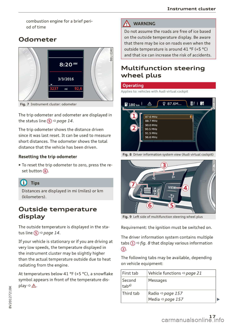
Fig. 7 Instrument cluster: odometer
The trip odometer and odometer are displayed in
the status line ©) > page 14.
The trip odometer shows the distance driven
since it was last reset. It can be used to measure
short distances. The odometer shows the total
distance that the vehicle has been driven.
Resetting the trip odometer
> To reset the trip odometer to zero, press the re-
set button ©.
@ Tips
Distances are displayed in mi (miles) or km
(kilometers).
Outside temperature
display
The outside temperature is displayed in the sta-
tus line ©) > page 14.
If your vehicle is stationary or if you are driving at
very low speeds, the temperature displayed in
the instrument cluster may be slightly higher
than the actual temperature outside due to heat
radiating from the engine.
At temperatures below 41 °F (+5 °C), a snowflake
symbol appears in front of the temperature dis-
play > A\.
ZA WARNING
Do not assume the roads are free of ice based
on the outside temperature display. Be aware
that there may be ice on roads even when the
outside temperature is around 41 °F (+5 °C)
and that ice can increase the risk of accidents.
Multifunction steering
wheel plus
Applies to: vehicles with Audi virtual cockpit
B180im! A
Fig. 8 Driver information system view (Audi virtual cockpit)
Fig. 9 Left side of multifunction steering wheel plus
Requirement: the ignition must be switched on.
The driver information system contains multiple
tabs @ © fig. 8 that display various information
®.
The following tabs may be available, depending
on vehicle equipment:
First tab Vehicle functions > page 21
Second Messages
tab?
Third tab Radio > page 157
Media > page 157
17