ECU AUDI A3 SEDAN 2017 Owners Manual
[x] Cancel search | Manufacturer: AUDI, Model Year: 2017, Model line: A3 SEDAN, Model: AUDI A3 SEDAN 2017Pages: 400, PDF Size: 67.32 MB
Page 6 of 400
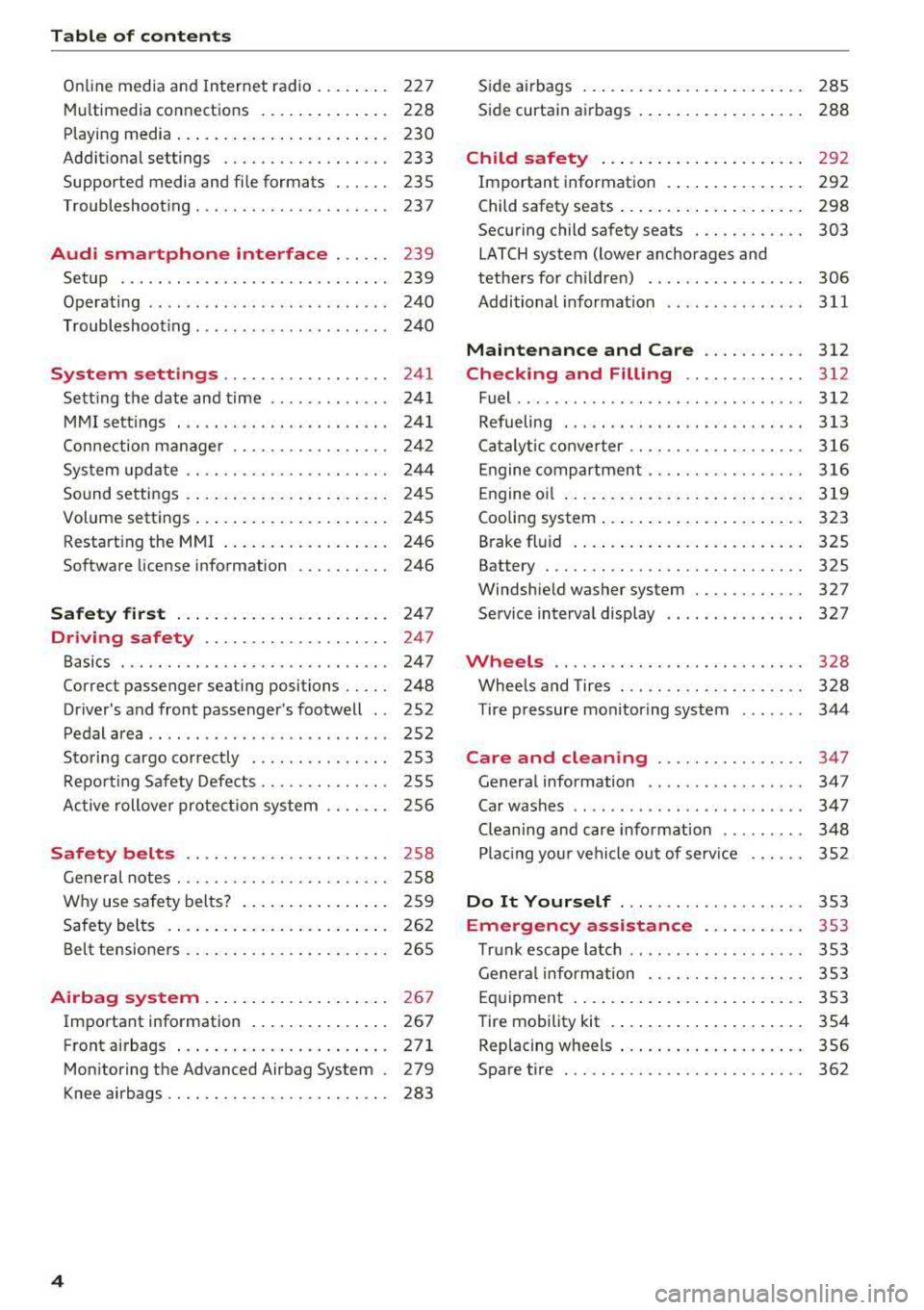
Table of content s
Online media and Internet radio . . . . . . . . 227
Mu ltim edia connections . . . . . . . . . . . . . . 228
Playing media . . . . . . . . . . . . . . . . . . . . . . . 230
Addit ional se ttings . . . . . . . . . . . . . . . . . . 233
Supported media and file formats . . . . . . 235
Troubleshoot ing ................. ... . 237
Audi smartphone interface . . . . . . 239
Setup . . . . . . . . . . . . . . . . . . . . . . . . . . . . . 239
Operating . . . . . . . . . . . . . . . . . . . . . . . . . . 240
Troubleshoot ing . . . . . . . . . . . . . . . . . . . . . 240
System settings . . . . . . . . . . . . . . . . . . 241
Sett ing the date and time . . . . . . . . . . . . . 24 1
MMI se ttings . . . . . . . . . . . . . . . . . . . . . . . 241
Con nection ma nager . . . . . . . . . . . . . . . . . 242
System update . . . . . . . . . . . . . . . . . . . . . . 244
Sound settings . .... .. ..... ... .. .. .. .
Volume settings .... .. ..... ... .. .. .. .
Restarting the
MMI . .. ..... ... .. .. .. .
Software license information 2
4 5
245
246
246
Safety first . . . . . . . . . . . . . . . . . . . . . . . 247
Driving safety . . . . . . . . . . . . . . . . . . . . 247
Basics . . . . . . . . . . . . . . . . . . . . . . . . . . . . . 247
Correct passenger seating positions . . . . . 248
Driver 's and front passenger's footwell . . 252
Pedal area . . . . . . . . . . . . . . . . . . . . . . . . . . 252
Sto ring cargo co rrectly . . . . . . . . . . . . . . . 253
R epo rting Safety Defects . . . . . . . . . . . . . . 255
Ac tive rollove r prote ct io n system 256
Safety belts . . . . . . . . . . . . . . . . . . . . . . 258
Gene ral notes . . . . . . . . . . . . . . . . . . . . . . . 258
W hy use safety belts? . . . . . . . . . . . . . . . . 259
Safety belts . . . . . . . . . . . . . . . . . . . . . . . . 262
Belt tensione rs . . . . . . . . . . . . . . . . . . . . . . 265
Airbag system . . . . . . . . . . . . . . . . . . . . 26 7
Important information . . . . . . . . . . . . . . . 267
Front airbags ... ... ... .... ... .. .. .. . 271
Mon itor ing the Advanced Airbag System . 279
K nee airbags . . . . . . . . . . . . . . . . . . . . . . . . 283
4
S ide a irbags . . . . . . . . . . . . . . . . . . . . . . . . 285
Side curtain airbags . . . . . . . . . . . . . . . . . . 288
Child safety . . . . . . . . . . . . . . . . . . . . . . 292
Important information . . . . . . . . . . . . . . . 292
Child safety seats . . . . . . . . . . . . . . . . . . . . 298
Securing child safety seats . . . . . . . . . . . . 303
LATCH system (lower anchorages and
tethers for c hildren) . . . . . . . . . . . . . . . . . 306
Additional informat ion ........ ..... .. 311
Maintenance and Care ........... 312
Checking and Filling . . . . . . . . . . . . . 312
Fuel ......... .... ... ............... 312
Refueling . . . . . . . . . . . . . . . . . . . . . . . . . . 313
Ca talytic conve rter .. .. .. ........... .. 316
Engine compar tment .. ... .......... .. 316
Engine o il . . . . . . . . . . . . . . . . . . . . . . . . . . 3 19
Cooling system . . . . . . . . . . . . . . . . . . . . . . 323
Brake fluid . . . . . . . . . . . . . . . . . . . . . . . . . 325
Battery . . . . . . . . . . . . . . . . . . . . . . . . . . . . 325
Windshie ld washer system . . . . . . . . . . . . 327
Service interva l display 327
Wheels .... .. . ... .. .. ........... .. 328
Wheels and Tires . . . . . . . . . . . . . . . . . . . . 328
Tire pressure monitoring system 344
Care and cleaning . . . . . . . . . . . . . . . . 347
Genera l information . . . . . . . . . . . . . . . . . 347
Car washes . . . . . . . . . . . . . . . . . . . . . . . . . 347
Cleaning and care informat ion . . . . . . . . . 348
Plac ing your vehi cle ou t of serv ice 352
Do It Yourself . . . . . . . . . . . . . . . . . . . . 353
Emergency assistance . . . . . . . . . . . 353
T ru nk escape la tch . . . . . . . . . . . . . . . . . . . 353
Genera l info rmation . . . . . . . . . . . . . . . . . 353
Eq uipment . . . . . . . . . . . . . . . . . . . . . . . . . 353
T ire mobility kit . . . . . . . . . . . . . . . . . . . . . 354
Replacing wheels . . . . . . . . . . . . . . . . . . . . 356
Spare t ire . . . . . . . . . . . . . . . . . . . . . . . . . . 362
Page 30 of 400
Cockpit over view
The brake booster remains active for a br ief peri
od of time after switching off the ignition. To se
cure the vehicle from ro lling away, move these
lector lever in the P position or set the parking
brake.
A WARNING
- Read and follow the warnings in
¢ page 316, Working in the engine com
partment
before open ing the hood and
check ing the b rake fl uid level.
- If the bra ke system indicator light does not
tu rn off o r it t urns on while driv ing, the
bra ke fluid level in the reservoir is too low ,
and this inc reases the risk of an acc iden t.
Stop the vehicle and do not continue dr iv
ing. See an authorized Audi dealer or au
tho rized Audi Service Facility for ass istance .
- If the bra ke sys tem indicator light turns on
together with the ABS and ESC indicator
lights, the ABS/ESC regulating function may
be malfunctioning. Functions that stabilize
the vehicle are no longer ava ilable. This
could cause the rear of the ve hicle to
swerve, which increases the risk that the ve hicle will slide . Do not continue driving . See
an aut ho rize d Aud i dea le r o r authori zed
Audi Service Facility for assistance .
PARK!<®)/ ~ Electromechanical parking
brake
If the -(USA models) I . (Canada models)
indicator light t urns on, the park ing brake was
set.
I f the
-(USA models)/ . (Canada mode ls) in
dicator light blinks, the braking fo rc e is not b uild
ing up enoug h or not b uilding up at all. Select the
P selector lever position to help secure the vehi
cle. Make sure the indicator lig ht is off before you
s tart dr iv ing .
There is a mal function in the park ing brake. Dr ive
to an author ized Audi dealer or author ized Audi
Serv ice Facility immediately to have the malfunc
tion corrected .
1'11j1j;j:lj :j;fj~~ (USA models ) / DJ (Can ada mod
els ) Par king brake auto release unava ilable
28
If this message appears, press the brake pedal
first and then release the parking brake.
1!1Jj1J;j:lj :J;f:U~ (USA model s) I DJ (Canada mod
els) C aution: Vehicle parked too steep
If the indica to r li gh t blin ks and the message ap
pears, there is not enoug h braking powe r to se
cu re the ve hicl e. Th e b rakes have ove rheate d. The
vehicle could roll away even o n a small in cli ne .
l91j;l1;j:lj :);f:U~ ( USA model s) / DJ (Canada mod
el s) Parking brake is applied
If this message appears, press the brake peda l
first and then release the parking brake if neces
sa ry .
(D Tips
For additional informat ion on t he parking
brake, see
¢ page 83.
-L Cooling system
• Switch off engine and check coolant level!
See owner's manual
• S top vehicle and ch eck coolant le vel! See
owner's manual
The coolant level is too low .
Do not continue driving and switch the engine
off. Ch eck the coolant level ¢
page 323 .
Plug -in hybrid d rive*: See ¢ page 10 4.
- If the coo lant level is too low, add coolant
¢
page 323 . Only continue dr iving once the in
dicator light turns off.
• Coolant temperature too high! L et engine
run with vehicle stationary
Let the engine ru n at idle for a few minutes to
cool off , until the indicator lig ht turns off .
-If the indicator light does not turn off , do not
cont inue driving the veh icle. See an authori zed
Audi dea le r or authori zed Audi Service Facility
for assistance.
.,,.
Page 34 of 400
Cockpit over view
The engine speed limitation deactivates once the
engine is no longer in the critica l temperature
range and you have released the acce lerator ped
al once.
If the engine speed limitation was activated by
an engine contro l ma lfunction, the
II or Im in
d icator light a lso t urns on . Make sure the eng ine
speed does not go above the speed displayed, for
examp le when downsh ift ing. Drive to an author
ized A udi dealer or authorized Aud i Service Facili
ty immediately to have the malfunct ion correct
ed.
'l::cr., Engine oil level (MIN)
II Plea se che ck oil level
You may continue driving for the t ime being .
Check the engine oil leve l as soon as possib le
¢ page 319.
- If the engine oil level is too low, add engine o il
¢ page 321 , Checking the engine oil level and
adding engine
oil.
- If the engine oil level is correct and the indica
tor light st ill turns on , drive at low eng ine
speed to an autho rized Aud i dealer o r autho r
ized Audi Service Facility.
~ Engine oil sensor
II Oil l evel sen sor : system fault!
The sensor to check the engine oil leve l has
fa iled. Drive to an autho rized Aud i dea le r o r a u
thor ized Audi Se rvice Fac il ity immediate ly to have
the m alfu nction co rrected.
(D Note
Refer to the desc ription in the Owner 's Man
ual ¢ page 3 21, Checking the engine oil level
and adding engine
oil.
io Tank system
Ve hicles with plug -in hybrid drive* : ¢page 105 .
H Please r efuel
The first time the indicator light turns on and the
message appears, there a re approximately 1.8
32
gallons (7 liters) o f fuel in the tank on front
whee l drive vehicl es, or approximate ly
2.2 ga l
l ons
(8 .5 liters) of fue l in the tank on a ll w heel
drive veh icles.
H Please refuel immediately
If the indicato r light turns on the message ap
pe ars, the fuel tan k is a lmost empty. Refue l the
vehicle immed ia tely.
H Tank system: malfunction! Plea se contact
Servi ce
T here is a ma lfunction in the f uel tank system .
Drive to an authorized A udi deal er or authorized
Audi Se rvice Facility immed iate ly to have the
malfunction corrected .
(D Tips
For more information on fue ling, see
¢ page 313.
~ Washer fluid level
m Please add washer fluid
Fill the washe r fl uid fo r the windshie ld washer
system and the head light washer system* when
the ignit ion is switched off
¢ page 327.
'+>' Windshield wipers
a 111/indshield wiper: system fault!
Ther e is a ma lf u nction with the winds hield wip
ers.
Drive to an authorized A udi dealer or authorized
Audi Service Facility immediate ly to have the
malfunction corrected.
~ Driver's door*
fl Driver 's door: malfunction ! Sh ift to P before
leav ing veh icle. See owner's manual
There is a ma lfunction in the driver's door. Se lect
the P selector lever position (automatic transmis-
s ion) to secure the vehicle.
..,.
Page 39 of 400
a, a, ..... N
" N .... 0 N > 00
"'Pull on the door handle to open the door.
Locking the vehicle
"'Place the selector lever in the P position (auto
matic transmissions), or e lse the vehicle will
not be able to lock.
"'To lock the vehicle, close the door and touch
the sensor on the door handle
once ¢ fig. 23,
¢_& .Do not hold the door hand le while doing
this.
Unlocking and locking the vehicle can only be
done at the front doors . The remote contro l key
cannot be more than approx imately 5 ft ( 1.5 m)
away from the door handle. It makes no differ
ence whether the remote control key is in you r
jacket pocket, purse or br iefcase .
If you hold the door handle while locking, this
can impair the locking function .
The door cannot be opened for a br ief period di
rect ly after locking it. This allows you the oppor
tunity to check that the driver's door is locked .
The settings in the Infotainment system deter
mine if the enti re vehicle or only one of the doors
is unlocked when unlocking the vehicle
¢page 38.
A WARNING
Read and following all warnings ¢ A in De
scription on page 34.
(!j) Tips
If your vehicle is left stand ing for a long peri
od of time, note the following:
-The proximity sensor switches off after a
few days to save energy. You then have to pull once on the door handle to unlock the
vehicle and a second time to open it.
-The energy management system gradually turns off unnecessary convenience functions
to prevent the vehicle battery from draining
and to maintain the vehicle's ab ility to start
for as long as possib le . You may not be able
to unlock your vehicle using the convenience
key.
-
Open ing and closing
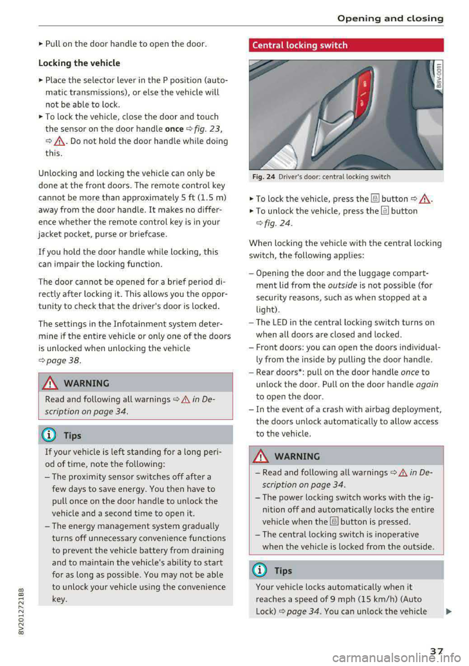
Central locking switch
Fig. 24 Drive r's doo r: centra l lock ing switc h
"'To lock the vehicle, press the !ill button ¢_& .
"'To unlock the vehicle, press the Im button
¢ fig . 24.
When locking the vehicle with the central locking
switch, the following applies:
-Opening the door and the luggage compart
ment lid from the
outside is not possible (for
security reasons, such as when stopped at a
light) .
- The L ED in the central locking sw itch turns on
when all doors are closed and locked.
- Front doors: you can open the doors individual ly from the inside by pulling the door handle.
- Rear doors*: pull on the door handle
once to
unlock the door . Pull on the door handle
again
to open the door .
- In the event of a crash with airbag deployment, the doors unlock automatically to allow access
to the vehicle.
A WARNING
-- Read and following all warnings¢ A in De-
scription on page 34 .
- The power locking switch works with the ig
nition off and automatical ly locks the entire
veh icle when the[§] button is pressed.
- The central locking switch is inoperative
when the vehicle is locked from the outs ide.
@ Tips
Your vehicle locks automatically when it
reaches a speed of 9 mph (15 km/h) (Auto
Lock) ¢
page 34. You can unlock the vehicle
37
Page 44 of 400
Opening and closin g
® Central switch* for opening or closing a ll side
windows at the same time
A WARNING
- Always remove the ignition key when you
leave your vehicle, even for a short period of
time. This applies particularly when children remain in the vehicle. Otherwise the chil
dren could start the engine or operate e lec
trical equipment such as power windows,
wh ich increases the r isk of injury. The power
windows continue to function until the dr iv
er's door or front passenger's door has been
opened .
- Pay ca refu l attent ion when closing the win
dows. Pinching cou ld cause serious injuries .
- When locking the vehicle from outside, the
vehicle must be unoccupied since the win
dows can no longer be opened in an emer
gency.
(D Tips
After turning the igni tion off you can still
open and close the windows for approximate ·
ly 10 seconds . The power w indows do not
switch off until the driver's door or front pas
senger's door has been opened.
Convenience opening/closing
App lies to: ve hicles w ith conve nien ce opening/clos ing
-
All of the windows and the panorama glass roof*
can be opened/closed at the same time.
For power top conven ience opening/closing, note
the information
in c:> page 45 .
Convenience opening feature
.,. Press and hold the open butto n[@] on the re
mote control key until all w indows and the pan
o rama g lass roof* have reached the desired po
sition . Or
.,. Hold the key in the driver's door lock unti l all
windows and the panorama glass roof * have
reached the desired pos ition.
42
Convenience closing fe ature
.,. Press the ~ button on the remote cont rol key
until a ll windows and the panorama g lass roof*
are closed
c:> A_ . Or
.,. Applies to: vehicles with convenience key: touch
the sensor on one of the front door handles and
cont inue touching it unti l all of the windows
and the panorama glass roof* are closed. Do
not place your hand in the door handle when
doing this .
.,. Hold the key in the dr ive r's door lock in the lock
position u ntil all w indows and the panorama
glass roof * are closed
c:> A_ .
The function can be sw itched on/off in the Info
ta inment system
c:> poge 38.
A WARNING
- Never close the w indows or panorama glass
roof* ca relessly or in an uncontrolled man
ner, because this increases the risk of injury.
- For secur ity reasons, the windows and the
pano rama g lass roo f* can only be opened
and closed with the remote control key at a
maximum distance of approximately 6.5
feet (2 m) away from the vehicle. Always
pay attention when using
the [@] button to
close the windows and the panorama g lass
roof* so that no one is pinched. The closing
process w ill stop immediately when
the@
button is re leased.
Correcting power window malfunctions
You con reactivate the one -touch up/down func
tion if it malfunctions .
.,. Pull the power window switch until the window
is completely raised .
.,. Release the switch and pull it up aga in fo r at
least one second .
Page 49 of 400
a, a, ..... N
" N ..... 0 N > 00
Power top: operation currently not possible.
Outside temperature too low
The power top will not open whe n the te mpe ra
ture iS belOW
-5 Of ( - 15 ° ( ).
Power top: operation currently not po ssible .
Speed too high
If yo u go above 30 mph (SO km/h), t he power
top ca nnot be operated d ue to safety reaso ns.
Reduce the vehicl e speed to close or open the
power top.
Power top: not secur e. Speed too high
This message appea rs if you go above 30 mph
(SO km/h) when ope rating the power top . Reduce
the vehicle speed and operate the power top
again .
Power top: malfunction! You may continue driv
ing
Thi s message appears if there is a ma lf u ncti on in
the system. Try to open or close the power top
again.
If the message st ill appea rs, have the mal
f u nction corrected by an authorized Aud i dealer
or author ized Audi Se rvice Facility .
A WARNING
Never drive whe n the powe r top is not locked
co rrectly . The w ind from driving cou ld cause
t he pow er top to open . This can resul t in inju
r ies an d dam age to the vehicle.
Wind deflector
Appl ies to: ve hicles with wind deflecto r
The wind deflector redu ces air movemen t in the
passenger compar tment in order to make driving
more comfortab le.
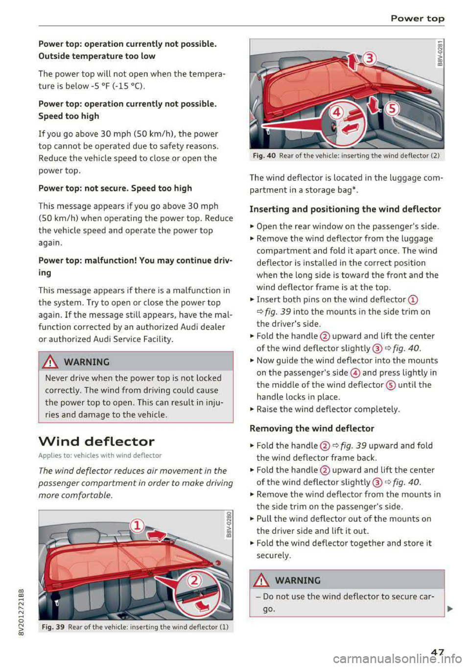
F ig. 39 Re ar of th e vehicle: inserting th e wind def lecto r (1)
Power top
~ a, N 0 > a, m
Fig . 40 Rea r o f th e ve hicle : inserting th e w ind deflecto r (2)
The w ind defl ector is located i n the l uggage com
partmen t in a storage b ag*.
Inserting and positioning the wind deflector
.,. Open the rear window on the passenger's side.
.,. Remove the w ind deflector from the l uggage
compa rtment and fold it apart once . The w ind
deflector is insta lled in the cor rect position
w hen the long side is towa rd th e fron t and the
w ind deflec to r fra me is a t th e to p .
.,. Insert bot h pins on t he wind deflec tor (D
¢ fig . 39 into the mounts in the side trim on
the dr iver's side .
.. Fold the handle @upward and lift the center
of t he wind deflector
sli ghtly @¢ fig. 40.
.,. Now guide the wind deflector into the mou nts
on t he passenger's
side © and press lightly in
t he middle of the wind deflector ® unti l the
ha ndle locks in place .
.,. Rai se the win d de flector completely .
Removing the wind deflector
.,. Fold th e handle @¢ fig. 39 upwa rd and fold
t he wind deflector frame back .
.,. Fold the handle@upward an d lift t he center
of t he wind def lec to r
slightly @¢ fig. 40.
.,. Remove the w ind deflector fr om the moun ts in
t he side t rim on the p assenger's side .
.,. Pull the w ind deflec to r out of the mounts on
the dr iver side and lift it out .
.. Fold th e wind def lector together and store it
secure ly.
A WARNING
=
- Do not use t he wind deflecto r to sec ure car -
go.
~
47
Page 51 of 400
a, a, ..... N
" N ..... 0 N > 00
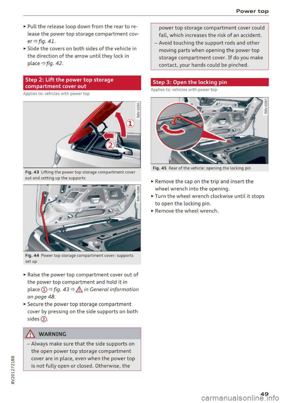
.. Pull the release loop down from the rear to re
lease the power top storage compartment cov
er ¢ fig. 41 .
.. Slide the covers on both sides of the vehicle in
the direction of the arrow until they lock in
place
¢ fig . 42 .
Step 2 : Lift the power top storage
compartment cover out
Appl ies to: vehicles wit h powe r top
Fig. 43 Lift ing t he powe r top sto rage compa rtment cove r
ou t ahd setting up t he supports
Fig. 44 Power to p storag e com pa rtm ent cove r: suppor ts
set up
.. Raise the power top compartment cover out of
the power top compartment and hold it in
place@¢ fig. 43 <:> .&, in General information
on page 48 .
.. Secure the power top stora ge compa rtment
cover by pressing on the side supports on both
sides@.
A WARNING
-Always make sure that the side supports on
the open power top storage compartment cover are in place, even when the power top
is not fully open or closed. Otherw ise, the
Power top
power top storage compartment cover could
fall, which increases the r isk of an accident.
- Avoid touching the support rods and other
moving parts when open ing the power top
storage compartment cover . If do you make
contact, your hands could be pinched.
Step 3: Open the locking pin
Applies to: veh icles w ith power top
Fig. 4 5 Rear of the veh icle : open ing the lock ing pin
.. Remove the cap on the trip and insert the
wheel wrench into the opening .
.. Turn the wheel wrench clockwise until it stops
to open the locking pin .
.. Remove the wheel wre nch .
49
Page 52 of 400
Power top
Step 4: Close the power top
Applies to: vehicles w ith power top
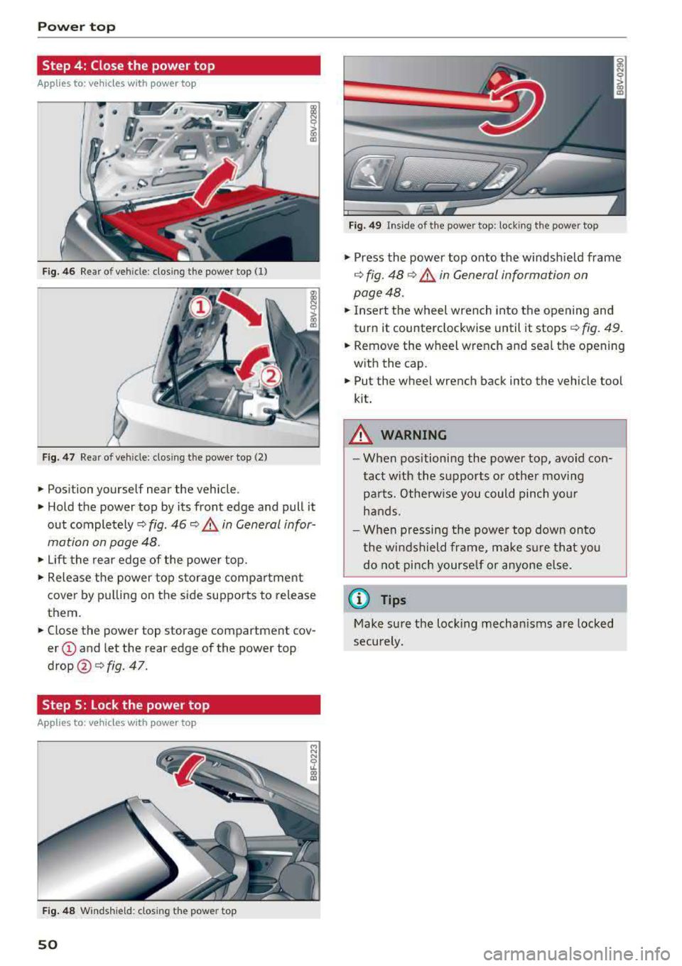
Fig. 46 Rear of vehicle: closing the power top (1)
Fig. 47 Rear of veh icle: clos ing the power top (2)
• Position yourself near the vehicle .
• Hold the power top by its front edge and pull it
out
completely¢ fig. 46 ~ .&. in General infor
mation on page 48.
• Lift the rear edge of the power top.
• Release the power top storage compartment
cover by pulling on the side supports to release
them.
• Close the power top storage compartment cov
er @ and let the rear edge of the power top
drop @¢ fig. 47.
Step 5: Lock the power top
Appl ies to : ve hicles w ith power top
Fig. 48 Windshield: closing the power top
50
Fig. 49 In side of the power top: locking the power top
• Press the power top onto the windshield frame
¢ fig. 48 ¢.&. in General information on
page 48.
• Insert the wheel wrench into the opening and
turn it counterclockwise until it stops¢
fig. 49.
• Remove the wheel wrench and seal the opening
with the cap.
• Put the wheel wrench back into the vehicle tool
kit.
&_ WARNING
- When positioning the power top, avoid con
tact with the supports or other moving
parts. Otherwise you could pinch your
hands.
- When pressing the power top down onto
the windshield frame, make sure that you
do not pinch yourself or anyone else.
(D Tips
Make sure the locking mechanisms are locked
securely.
Page 61 of 400
a, co .... N
" N .... 0 N > 00
_& WARNING
For safety reasons, the windshield wiper
blades should be replaced once or twice each
year .
(D Note
-The windshield wiper blades must only be
folded away when in the service position!
Otherwise, you risk damaging the paint on
the hood or the windshield wiper motor .
- You should not drive your vehicle or press
the windshield wiper lever when the wiper
arms are folded away from the windshield.
The windshield wipers would move back in
to their original position and could damage
the hood and windshield .
@ Tips
- You can also use the service position, for ex
ample, if you want to protect the windshield
from icing by using a cover.
- You cannot activate the service position
when the hood is open .
Replacing rear wiper blade
Applies to: vehicles with rear window wiper
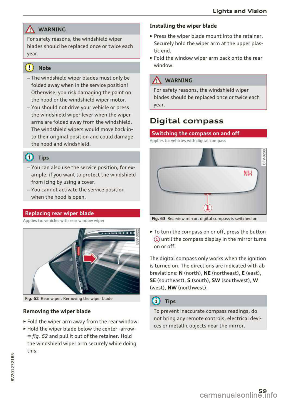
Fig. 62 Rear wiper : Removing the wiper bla de
Removing the wiper blade
"Fold the wiper arm away from the rear window .
" Hold the wiper blade below the center -arrow-
¢ fig. 62 and pull it out of the retainer . Hold
the windshield wiper arm securely while doing
this.
Lights and Vision
Installing the wiper blade
"Press the wiper blade mount into the retainer.
Securely hold th e wiper arm at the upper plas
tic end.
"Fold th e window wiper arm back onto the r ear
window.
_& WARNING
= -
For safety reasons, the windshield wiper
blades should be replaced once or twice each
year .
Digital compass
Switching the compass on and off
Applies to: vehicles with digital compass
Fig. 63 Rearview mir ror : digi tal compa ss is s wit c hed on
gi N 0
> u. m
"To turn the compass on or off, press the button
@until the compass display in the mirror turns
on or off.
The digital compass only works when the ignition
is turned on. The directions are indicated with ab
breviations:
N (north), NE (northeast), E (east) ,
SE (southeast), S (south), SW (southwest), W
(west) , NW (northwest) .
(D Tips
To prevent inaccurate compass readings, do
not bring any remote controls, electrical devi
ces or metallic objects near the mirror.
59
Page 66 of 400
Sea ts and stor age
Mov ing the head rest raints
.. T o move the head res traint up, ho ld it at the
sides with both hands and slide it upward unt il
you fee l it click into place .
.. To move the head restraint down, press the
button @¢ fig. 72 and slide the head restra int
downward.
R emov ing th e head rest raints
To remove the head restraints, the backrest must
be folded forward partially .
.. Remove the screwd river from the vehicle tool
k it
¢page 353 .
.. Release the backrest ¢ page 67 .
.. Press the button @ c::> fig. 72 and slide the head
restra int up as far as it can go .
.. Place the screwdriver in position @ in the
opening, press the button @ and pull the head
restra int out of the backrest at the same time
¢ &_ .
• Fold the backrest down until it latches secure ly
¢ &_ in Increasing the cargo area on
page
67.
Installing the head restraints
To install the head restraints, the backrest must
be folded forward partially .
.. Release the backrest c::> page 67.
.. Slide the posts on the head restraint down into
the gu ides unti l the posts click into place . You
should not be able to pull the head restra int
out of the backrest .
• Fold the backrest down un til it latches secure ly
¢ &_ in Increasing the cargo area on
page
67 .
_& WARNING
-Always read and fo llow the applicable warn
ings
c::> page 2 50, Proper adjustment of
head restraints.
- Only remove the rear seat head restraints
when necessary in order to install a child
safety seat
c::> page 292, Child safety. In
sta ll the head restra int aga in immediately
once the child safety seat is removed. Dr iv
ing with the head restra ints removed o r not
64
in the upright position increases the risk of
serio us injury .
Sockets
Applies to: vehicles with socket
-,:~
I '
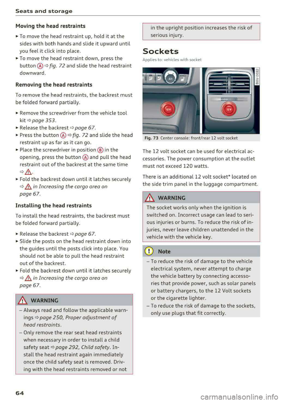
Fig. 73 Center console: front/rea r 12 volt socket
The 12 volt soc ket can be used for e lectr ica l ac
cessor ies. The power consum ption at the out let
mus t not exceed 120 w atts.
There is an add itiona l 12 volt socket * located on
the side trim panel in the luggage compa rtment.
_& WARNING
T he socke t works only w hen t he igni tion is
switche d on. Incorrec t usage c an lead to seri
ous injur ies or burns. To reduce the ri sk of in
juries, never leave children unattended in the vehicle wit h the vehicle key .
{[) Note
-
- T o red uce the risk of dam age to t he vehicle
electrical system, never attemp t to cha rge
the vehicle battery by connecting accesso ries that p rovide power, such as solar panels
or battery chargers, to the 12 Volt sockets
o r the ciga rette lighter.
- To reduce the risk of damage to the sockets, only use plugs t hat fit correctly.