manual AUDI A4 1995 B5 / 1.G AC System On Board Diagnostic Workshop Manual
[x] Cancel search | Manufacturer: AUDI, Model Year: 1995, Model line: A4, Model: AUDI A4 1995 B5 / 1.GPages: 91, PDF Size: 0.32 MB
Page 2 of 91
01-2
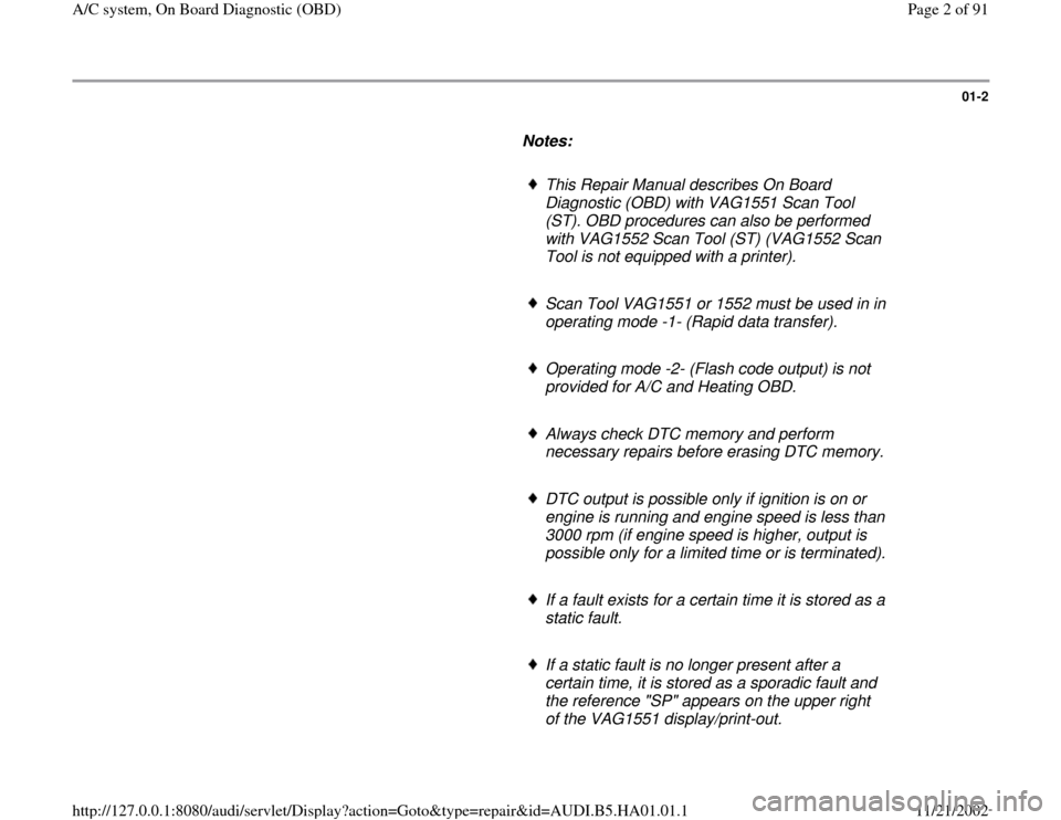
Notes:
This Repair Manual describes On Board
Diagnostic (OBD) with VAG1551 Scan Tool
(ST). OBD procedures can also be performed
with VAG1552 Scan Tool (ST) (VAG1552 Scan
Tool is not equipped with a printer).
Scan Tool VAG1551 or 1552 must be used in in
operating mode -1- (Rapid data transfer).
Operating mode -2- (Flash code output) is not
provided for A/C and Heating OBD.
Always check DTC memory and perform
necessary repairs before erasing DTC memory.
DTC output is possible only if ignition is on or
engine is running and engine speed is less than
3000 rpm (if engine speed is higher, output is
possible only for a limited time or is terminated).
If a fault exists for a certain time it is stored as a
static fault.
If a static fault is no longer present after a
certain time, it is stored as a sporadic fault and
the reference "SP" appears on the upper right
of the VAG1551 display/print-out.
Pa
ge 2 of 91 A/C s
ystem, On Board Dia
gnostic
(OBD
)
11/21/2002 htt
p://127.0.0.1:8080/audi/servlet/Dis
play?action=Goto&t
yp
e=re
pair&id=AUDI.B5.HA01.01.1
Page 14 of 91
01-11
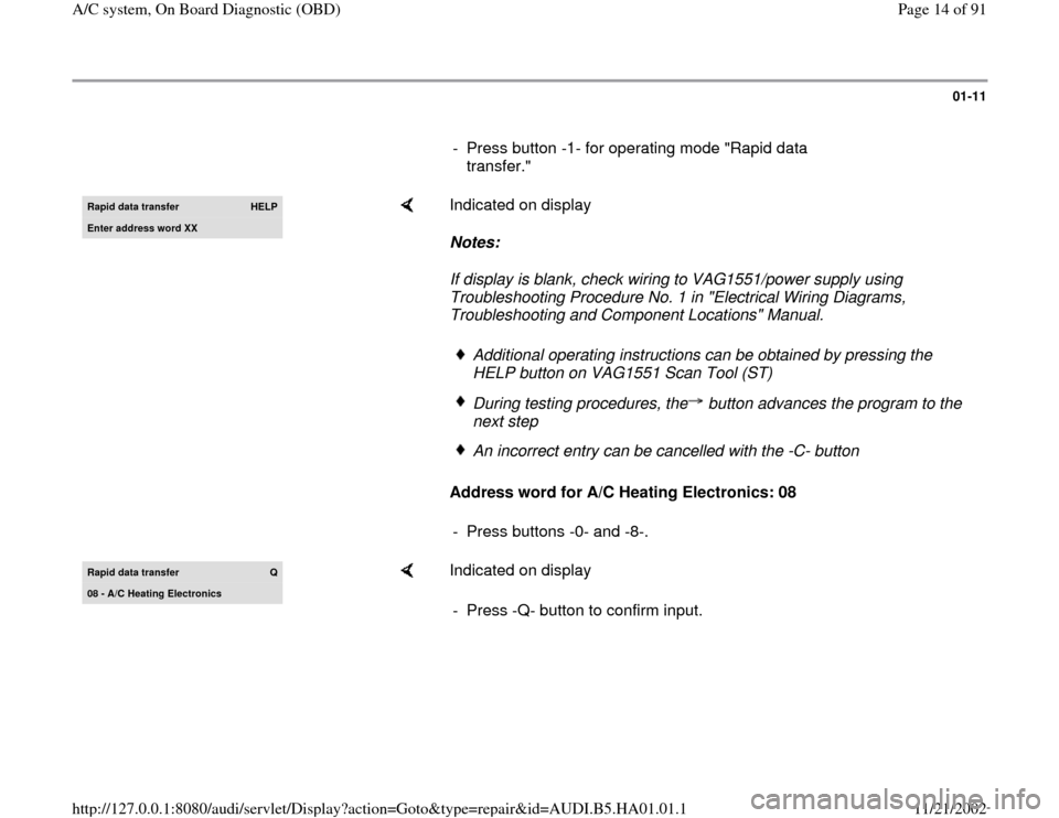
- Press button -1- for operating mode "Rapid data
transfer." Rapid data transfer
HELP
Enter address word XX
Indicated on display
Notes:
If display is blank, check wiring to VAG1551/power supply using
Troubleshooting Procedure No. 1 in "Electrical Wiring Diagrams,
Troubleshooting and Component Locations" Manual.
Address word for A/C Heating Electronics: 08
Additional operating instructions can be obtained by pressing the
HELP button on VAG1551 Scan Tool (ST) During testing procedures, the button advances the program to the
next step An incorrect entry can be cancelled with the -C- button
- Press buttons -0- and -8-.
Rapid data transfer
Q
08 - A/C Heating Electronics
Indicated on display
- Press -Q- button to confirm input.
Pa
ge 14 of 91 A/C s
ystem, On Board Dia
gnostic
(OBD
)
11/21/2002 htt
p://127.0.0.1:8080/audi/servlet/Dis
play?action=Goto&t
yp
e=re
pair&id=AUDI.B5.HA01.01.1
Page 31 of 91
01-24
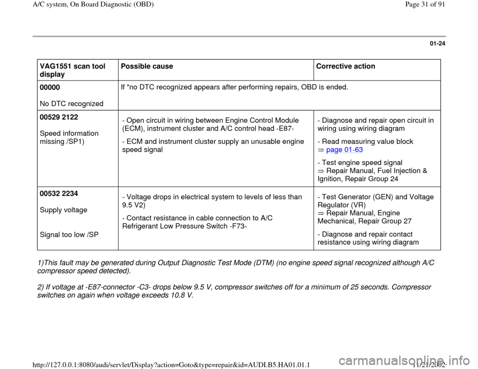
VAG1551 scan tool
display Possible cause
Corrective action
00000
No DTC recognized If "no DTC recognized appears after performing repairs, OBD is ended.
00529 2122
Speed information
missing /SP1) - Open circuit in wiring between Engine Control Module
(ECM), instrument cluster and A/C control head -E87-
- ECM and instrument cluster supply an unusable engine
speed signal - Diagnose and repair open circuit in
wiring using wiring diagram
- Read measuring value block
page 01
-63
- Test engine speed signal
Repair Manual, Fuel Injection &
Ignition, Repair Group 24
00532 2234
Supply voltage
Signal too low /SP - Voltage drops in electrical system to levels of less than
9.5 V2)
- Contact resistance in cable connection to A/C
Refrigerant Low Pressure Switch -F73- - Test Generator (GEN) and Voltage
Regulator (VR)
Repair Manual, Engine
Mechanical, Repair Group 27
- Diagnose and repair contact
resistance using wiring diagram
1)This fault may be generated during Output Diagnostic Test Mode (DTM) (no engine speed signal recognized although A/C
compressor speed detected).
2) If voltage at -E87-connector -C3- drops below 9.5 V, compressor switches off for a minimum of 25 seconds. Compressor
switches on again when voltage exceeds 10.8 V.
Pa
ge 31 of 91 A/C s
ystem, On Board Dia
gnostic
(OBD
)
11/21/2002 htt
p://127.0.0.1:8080/audi/servlet/Dis
play?action=Goto&t
yp
e=re
pair&id=AUDI.B5.HA01.01.1
Page 33 of 91
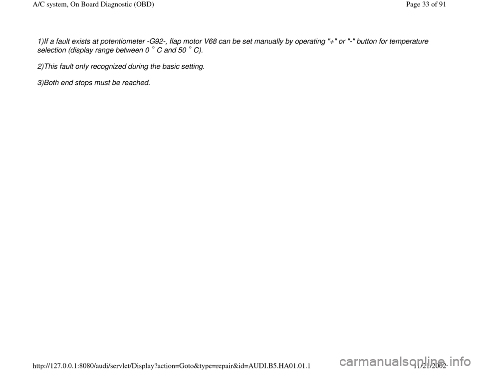
1)If a fault exists at potentiometer -G92-, flap motor V68 can be set manually by operating "+" or "-" button for temperature
selection (display range between 0 C and 50 C). 2)This fault only recognized during the basic setting.
3)Both end stops must be reached.
Pa
ge 33 of 91 A/C s
ystem, On Board Dia
gnostic
(OBD
)
11/21/2002 htt
p://127.0.0.1:8080/audi/servlet/Dis
play?action=Goto&t
yp
e=re
pair&id=AUDI.B5.HA01.01.1
Page 44 of 91
01-34
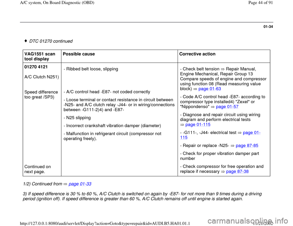
DTC 01270 continued
VAG1551 scan
tool display Possible cause
Corrective action
01270 4121
A/C Clutch N251)
Speed difference
too great /SP3)
Continued on
next page. - Ribbed belt loose, slipping
- A/C control head -E87- not coded correctly
- Loose terminal or contact resistance in circuit between
-N25- and A/C clutch relay -J44- or in wiring/connections
between -G111-2)4) and -E87-
- N25 slipping
- Incorrect crankshaft vibration damper (diameter)
- Malfunction in refrigerant circuit (compressor not
operating freely). - Check belt tension Repair Manual,
Engine Mechanical, Repair Group 13
Compare speeds of engine and compressor
using function 08 (Read measuring value
block) page 01
-63
- Code A/C control head -E87- according to
compressor type installed4) "Zexel" or
"Nippondenso" page 01
-57
- Diagnose and repair circuit using wiring
diagram and perform electrical tests
page 01
-115
- -G111-, -J44- electrical test page 01
-
115
- Repair or replace -N25- page 87
-85
- Check for proper vibration damper part
number
- Check compressor for free operation and
replace if necessary page 87
-38
1/2) Continued from page 01
-33
3) If speed difference is 30 % to 60 %, A/C Clutch is switched on again by -E87- for not more than 9 times during a driving
period (ignition off). If speed difference is greater than 60 %, A/C Clutch remains off until engine is started again.
Pa
ge 44 of 91 A/C s
ystem, On Board Dia
gnostic
(OBD
)
11/21/2002 htt
p://127.0.0.1:8080/audi/servlet/Dis
play?action=Goto&t
yp
e=re
pair&id=AUDI.B5.HA01.01.1
Page 65 of 91
01-46
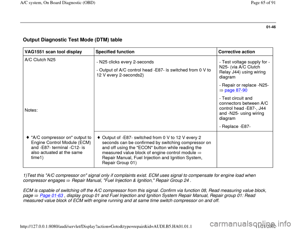
Output Diagnostic Test Mode (DTM) table
VAG1551 scan tool display
Specified function
Corrective action
A/C Clutch N25
Notes: - N25 clicks every 2-seconds
- Output of A/C control head -E87- is switched from 0 V to
12 V every 2-seconds2) - Test voltage supply for -
N25- (via A/C Clutch
Relay J44) using wiring
diagram
- Repair or replace -N25-
page 87
-90
- Test circuit and
connectors between A/C
control head -E87-, J44
and -N25- using wiring
diagram
- Replace -E87-
"A/C compressor on" output to
Engine Control Module (ECM)
and -E87- terminal -C12- is
also actuated at the same
time1)
Output of -E87- switched from 0 V to 12 V every 2
seconds can be confirmed by switching compressor on
and off using the "ECON" button while reading the
measured value block of engine control module
Repair Manual, Fuel Injection and Ignition System,
Repair Group 01)
1)Test this "A/C compressor on" signal only if complaints exist. ECM uses signal to compensate for engine load when
compressor engages Repair Manual, "Fuel Injection & Ignition," Repair Group 24 . ECM is capable of switching off the A/C compressor from this signal. Confirm via function 08, Read measuring value block,
page Page 01
-63
, display group 01 and Fuel Injection and Ignition System Repair Manual, Repair group 01: Read
measured value block of ECM with engine running and at same time switch compressor on and off.
Pa
ge 65 of 91 A/C s
ystem, On Board Dia
gnostic
(OBD
)
11/21/2002 htt
p://127.0.0.1:8080/audi/servlet/Dis
play?action=Goto&t
yp
e=re
pair&id=AUDI.B5.HA01.01.1