ignition AUDI A4 1995 B5 / 1.G AEB Engine Throttle Valve Control Module And Checking
[x] Cancel search | Manufacturer: AUDI, Model Year: 1995, Model line: A4, Model: AUDI A4 1995 B5 / 1.GPages: 38, PDF Size: 0.12 MB
Page 2 of 38
24-100
Function
Idle speed stabilization is integrated in the
throttle valve control module -J338-. In the
housing opposite the throttle valve are Throttle
Position (TP) sensor -G69-, Closed Throttle
Position (CTP) switch -F60-, throttle drive -G186-
and angle sensor -1- for throttle drive -G187-.
The housing should not be opened.
The individual components cannot be replaced or
mechanically adjusted. All adjustments are
accomplished by the VAG 1551 Scan Tool (ST)
using the "Basic Setting" function 04.
If the complete throttle valve control module is
without power (i.e. disconnected), the throttle
valve assumes a mechanical closed throttle
position that results in an increased idle speed of
1200-1300 RPM (with engine at operating
temperature).
If only the Throttle Position (TP) actuator -V60- is
without power, the throttle valve also assumes a
mechanical closed throttle position (limp-home
position), but because the signal from the CTP
switch -F60- can still be recognized, a nearly
"normal" idle speed of approx. 900 RPM is
maintained with a corresponding reduction of the
ignition timing advance.
If the Engine Control Module (ECM) recognizes a
Pa
ge 2 of 38 Throttle valve control module, checkin
g
11/19/2002 htt
p://127.0.0.1:8080/audi/servlet/Dis
play?action=Goto&t
yp
e=re
pair&id=AUDI.B5.FU02.24.2
Page 4 of 38
24-101
Throttle valve control module power
supply, checking
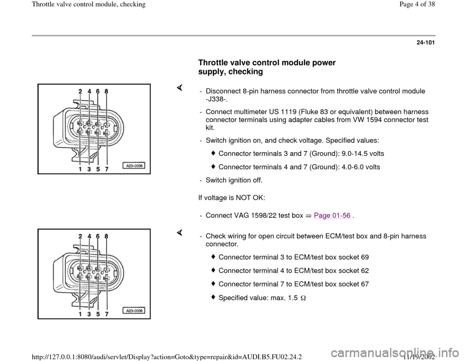
If voltage is NOT OK: - Disconnect 8-pin harness connector from throttle valve control module
-J338-.
- Connect multimeter US 1119 (Fluke 83 or equivalent) between harness
connector terminals using adapter cables from VW 1594 connector test
kit.
- Switch ignition on, and check voltage. Specified values:
Connector terminals 3 and 7 (Ground): 9.0-14.5 volts
Connector terminals 4 and 7 (Ground): 4.0-6.0 volts
- Switch ignition off.
- Connect VAG 1598/22 test box Page 01
-56
.
- Check wiring for open circuit between ECM/test box and 8-pin harness
connector.
Connector terminal 3 to ECM/test box socket 69
Connector terminal 4 to ECM/test box socket 62
Connector terminal 7 to ECM/test box socket 67
Specified value: max. 1.5
Pa
ge 4 of 38 Throttle valve control module, checkin
g
11/19/2002 htt
p://127.0.0.1:8080/audi/servlet/Dis
play?action=Goto&t
yp
e=re
pair&id=AUDI.B5.FU02.24.2
Page 11 of 38
24-105
Continuation
- Switch ignition off.
- Connect VAG 1598/22 test box to ECM harness
connector Page 01
-56
.
- Connect multimeter US1119 (Fluke 83 or
similar) and check resistance between test box
sockets 67and 69.
Specified value: max. 5.0
-
Open throttle slowly. Specified value: If resistance is NOT OK:
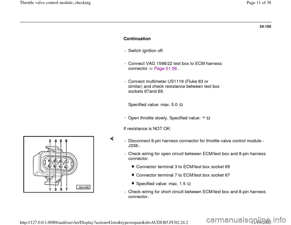
- Disconnect 8-pin harness connector for throttle valve control module -
J338-.
- Check wiring for open circuit between ECM/test box and 8-pin harness
connector.
Connector terminal 3 to ECM/test box socket 69
Connector terminal 7 to ECM/test box socket 67
Specified value: max. 1.5
- Check wiring for short circuit between ECM/test box and 8-pin harness
connector.
Pa
ge 11 of 38 Throttle valve control module, checkin
g
11/19/2002 htt
p://127.0.0.1:8080/audi/servlet/Dis
play?action=Goto&t
yp
e=re
pair&id=AUDI.B5.FU02.24.2
Page 16 of 38
24-109
- Compare display with specified values for idle
air control (display fields 1-4):
Display fields
1 2 3 4
Display group 55: Idle control
Display xxx RPM x.xx g/s x.xx g/s xxxx
Indicates Engine speed RPM
(in steps of 10 RPM) Regulating value-idle mass
air flow (idle air control) Learning value-idle
mass air flow Operating
conditions
Range 0-2550 RPM -2.80 to 4.17 g/s -1.94 to 2.22 g/s ---
Specified
value 820-900 RPM -1.11 to 1.11 g/s -1.11 to 1.11 g/s 0000
If engine speed is NOT OK
Page 24
-111
, Continuation
If display is NOT OK Page 24
-110
, Evaluating
display group 55
Explanation
Page 24
-110
If displayed values are OK:
-
Press button to advance program
sequence.
- Press buttons -0- and -6- to select "End Output"
function 06, and press -Q- button to confirm
input.
- Switch ignition off.
Pa
ge 16 of 38 Throttle valve control module, checkin
g
11/19/2002 htt
p://127.0.0.1:8080/audi/servlet/Dis
play?action=Goto&t
yp
e=re
pair&id=AUDI.B5.FU02.24.2
Page 19 of 38
24-111
Continuation
- Switch ignition off.
- Connect VAG 1598/22 test box to ECM harness
connector Page 01
-56
.
- Switch ignition on.
- With throttle valve in closed throttle position,
connect multimeter US 1119 (Fluke 83 or
equivalent), and check resistance between
ECM/test box sockets 59 and 66.
Specified value: 3-200 If resistance is NOT OK:
- Disconnect 8-pin harness connector from throttle
valve control module -J338-.
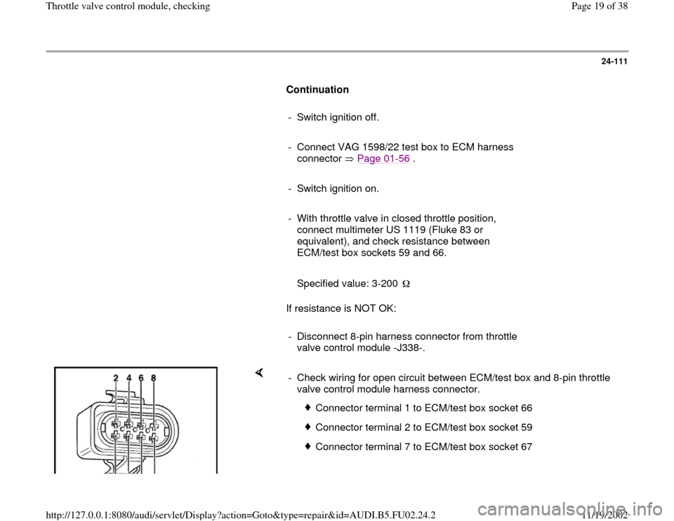
- Check wiring for open circuit between ECM/test box and 8-pin throttle
valve control module harness connector.
Connector terminal 1 to ECM/test box socket 66
Connector terminal 2 to ECM/test box socket 59
Connector terminal 7 to ECM/test box socket 67
Pa
ge 19 of 38 Throttle valve control module, checkin
g
11/19/2002 htt
p://127.0.0.1:8080/audi/servlet/Dis
play?action=Goto&t
yp
e=re
pair&id=AUDI.B5.FU02.24.2
Page 23 of 38
24-113
Throttle Position (TP) sensor, checking
Note:
Throttle Position (TP) sensor -G69- is located
inside the throttle valve control module -J338-.
Test conditions
Throttle valve in closed throttle position; if
necessary adjust accelerator pedal cable
Repair Manual, Fuel Supply System, Repair
Group 20
Cruise control adjustment OK
Power supply for throttle valve control
module OK; checking Page 24
-101
Checking
- Connect VAG 1551 or VAG 1552 scan tool and
press buttons -0- and -1- to insert "Engine
Electronics" address word 01 (with ignition
switched; engine not running) Page 01
-7 .
Rapid data transfer
HELP
Indicated on display
Pa
ge 23 of 38 Throttle valve control module, checkin
g
11/19/2002 htt
p://127.0.0.1:8080/audi/servlet/Dis
play?action=Goto&t
yp
e=re
pair&id=AUDI.B5.FU02.24.2
Page 25 of 38
24-114
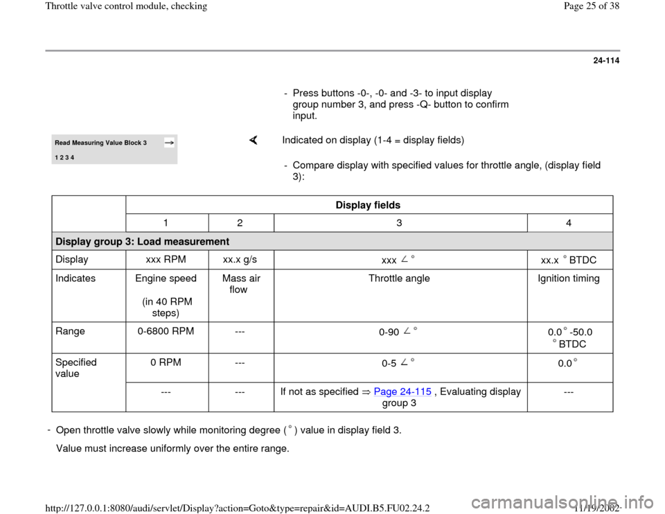
- Press buttons -0-, -0- and -3- to input display
group number 3, and press -Q- button to confirm
input. Read Measuring Value Block 3 1 2 3 4
Indicated on display (1-4 = display fields)
- Compare display with specified values for throttle angle, (display field
3):
Display fields
1 2 3 4
Display group 3: Load measurement
Display xxx RPM xx.x g/s
xxx
xx.x BTDC
Indicates Engine speed
(in 40 RPM
steps) Mass air
flow Throttle angle Ignition timing
Range 0-6800 RPM ---
0-90
0.0 -50.0
BTDC
Specified
value 0 RPM ---
0-5
0.0
--- --- If not as specified Page 24
-115
, Evaluating display
group 3
---
-
Open throttle valve slowly while monitoring degree ( ) value in display field 3. Value must increase uniformly over the entire range.
Pa
ge 25 of 38 Throttle valve control module, checkin
g
11/19/2002 htt
p://127.0.0.1:8080/audi/servlet/Dis
play?action=Goto&t
yp
e=re
pair&id=AUDI.B5.FU02.24.2
Page 27 of 38
24-115
- Press buttons -0- and -6- to select "End Output"
function 06, and press -Q- button to confirm
input.
- Switch ignition off.
Note:
The values displayed in display field 3 depend on
the calibration of the Throttle Position (TP)
sensor and do not correspond with the actual
throttle valve opening in degrees. The maximum
displayed value is 90.0 . If the throttle angle value does not increase
uniformly:
- Replace throttle valve control module -J338-.
- Carry out adaptation of throttle valve control
module to ECM Page 24
-119
.
- Check readiness code Page 01
-59
. If
Diagnostic Trouble Code (DTC) memory has
been erased, or ECM was disconnected,
generate new readiness code Page 01
-62
.
Evaluating display group 3
Pa
ge 27 of 38 Throttle valve control module, checkin
g
11/19/2002 htt
p://127.0.0.1:8080/audi/servlet/Dis
play?action=Goto&t
yp
e=re
pair&id=AUDI.B5.FU02.24.2
Page 29 of 38
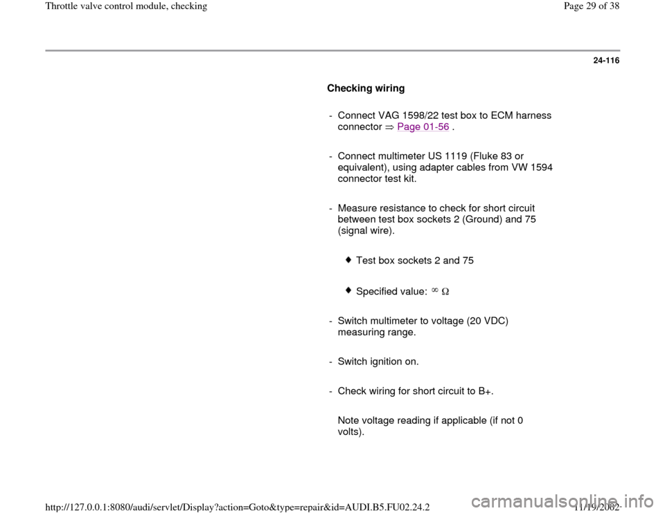
24-116
Checking wiring
- Connect VAG 1598/22 test box to ECM harness
connector Page 01
-56
.
- Connect multimeter US 1119 (Fluke 83 or
equivalent), using adapter cables from VW 1594
connector test kit.
- Measure resistance to check for short circuit
between test box sockets 2 (Ground) and 75
(signal wire).
Test box sockets 2 and 75
Specified value:
- Switch multimeter to voltage (20 VDC)
measuring range.
- Switch ignition on.
- Check wiring for short circuit to B+.
Note voltage reading if applicable (if not 0
volts).
Pa
ge 29 of 38 Throttle valve control module, checkin
g
11/19/2002 htt
p://127.0.0.1:8080/audi/servlet/Dis
play?action=Goto&t
yp
e=re
pair&id=AUDI.B5.FU02.24.2
Page 30 of 38
- Switch ignition off.
- Continue test, depending on whether or not
voltage was measured Page 24
-117
or page
Page 24
-118
.
Pa
ge 30 of 38 Throttle valve control module, checkin
g
11/19/2002 htt
p://127.0.0.1:8080/audi/servlet/Dis
play?action=Goto&t
yp
e=re
pair&id=AUDI.B5.FU02.24.2