sensor AUDI A4 1995 B5 / 1.G AFC Engine On Board Diagnostic Multiport Fuel Injection Workshop Manual
[x] Cancel search | Manufacturer: AUDI, Model Year: 1995, Model line: A4, Model: AUDI A4 1995 B5 / 1.GPages: 366, PDF Size: 1.21 MB
Page 228 of 366

Note on display field 8:
Deviations in display field 8 should only be considered after the oxygen sensor learning process at idle has been completed
display field 9.
Pa
ge 228 of 366 On Board Dia
gnostic
(OBD
) - Multi
port Fuel In
jection
(MFI
)
11/22/2002 htt
p://127.0.0.1:8080/audi/servlet/Dis
play?action=Goto&t
yp
e=re
pair&id=AUDI.B5.FU01.01.1
Page 229 of 366
01-164
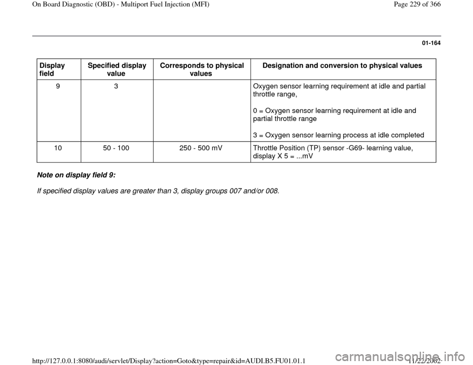
Display
field Specified display
value Corresponds to physical
values Designation and conversion to physical values
9 3 Oxygen sensor learning requirement at idle and partial
throttle range,
0 = Oxygen sensor learning requirement at idle and
partial throttle range
3 = Oxygen sensor learning process at idle completed
10 50 - 100 250 - 500 mV Throttle Position (TP) sensor -G69- learning value,
display X 5 = ...mV Note on display field 9:
If specified display values are greater than 3, display groups 007 and/or 008.
Pa
ge 229 of 366 On Board Dia
gnostic
(OBD
) - Multi
port Fuel In
jection
(MFI
)
11/22/2002 htt
p://127.0.0.1:8080/audi/servlet/Dis
play?action=Goto&t
yp
e=re
pair&id=AUDI.B5.FU01.01.1
Page 230 of 366
01-165
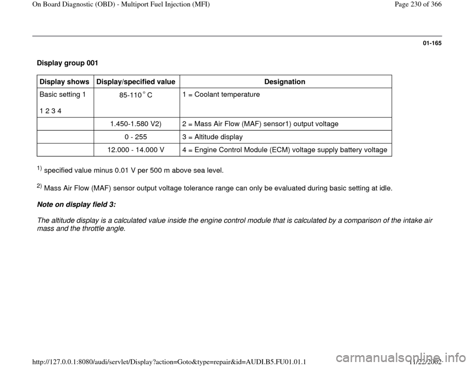
Display group 001 Display shows
Display/specified value
Designation
Basic setting 1
1 2 3 4 85-110 C
1 = Coolant temperature
1.450-1.580 V2) 2 = Mass Air Flow (MAF) sensor1) output voltage
0 - 255 3 = Altitude display
12.000 - 14.000 V 4 = Engine Control Module (ECM) voltage supply battery voltage
1) specified value minus 0.01 V per 500 m above sea level. 2) Mass Air Flow (MAF) sensor output voltage tolerance range can only be evaluated during basic setting at idle.
Note on display field 3:
The altitude display is a calculated value inside the engine control module that is calculated by a comparison of the intake air
mass and the throttle angle.
Pa
ge 230 of 366 On Board Dia
gnostic
(OBD
) - Multi
port Fuel In
jection
(MFI
)
11/22/2002 htt
p://127.0.0.1:8080/audi/servlet/Dis
play?action=Goto&t
yp
e=re
pair&id=AUDI.B5.FU01.01.1
Page 231 of 366
01-166
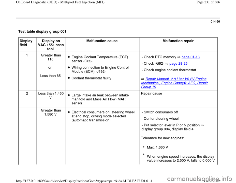
Test table display group 001 Display
field Display on
VAG 1551 scan
tool Malfunction cause
Malfunction repair
1 Greater than
110
or
Less than 85
Engine Coolant Temperature (ECT)
sensor -G62-
Wiring connection to Engine Control
Module (ECM) -J192-
Coolant thermostat faulty
Repair Manual, 2.8 Liter V6 2V Engine
Mechanical, Engine Code(s): AFC, Repair Group 19
- Check DTC memory page 01
-13
- Check -G62- page 28
-25
- Check engine coolant thermostat
2 Less than 1.450
V
Large intake air leak between intake
manifold and Mass Air Flow (MAF)
sensor Repair cause
Greater than
1.580 V Electrical consumers on, steering wheel
at end stop, driving mode selected
(automatic transmission)
Tolerance for new engines: - Switch consumers off
- Center steering wheel
- Put selector lever in P or N position
display group 004, display field 4
Max. 1.660 V
When engine speed increases, the display
value increases to 2.500 V, falls to 0.000 V
Pa
ge 231 of 366 On Board Dia
gnostic
(OBD
) - Multi
port Fuel In
jection
(MFI
)
11/22/2002 htt
p://127.0.0.1:8080/audi/servlet/Dis
play?action=Goto&t
yp
e=re
pair&id=AUDI.B5.FU01.01.1
Page 233 of 366
01-167
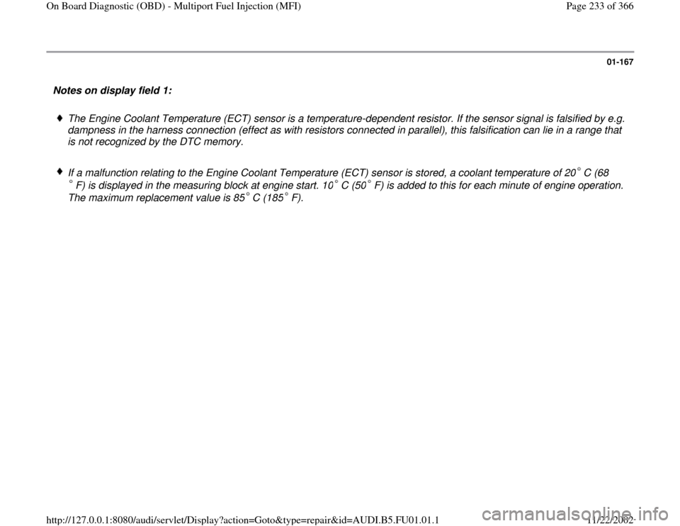
Notes on display field 1:
The Engine Coolant Temperature (ECT) sensor is a temperature-dependent resistor. If the sensor signal is falsified by e.g.
dampness in the harness connection (effect as with resistors connected in parallel), this falsification can lie in a range that
is not recognized by the DTC memory.
If a malfunction relating to the Engine Coolant Temperature (ECT) sensor is stored, a coolant temperature of 20 C (68
F) is displayed in the measuring block at engine start. 10 C (50 F) is added to this for each minute of engine operation.
The maximum replacement value is 85 C (185 F).
Pa
ge 233 of 366 On Board Dia
gnostic
(OBD
) - Multi
port Fuel In
jection
(MFI
)
11/22/2002 htt
p://127.0.0.1:8080/audi/servlet/Dis
play?action=Goto&t
yp
e=re
pair&id=AUDI.B5.FU01.01.1
Page 234 of 366

01-168
Display group 002 Display shows
Display/specified value
Designation
Basic setting 2
1 2 3 4 0.250 - 4.750 V 1 = Throttle position sensor voltage (idle to full throttle range)
0.250 - 1.275 V 2 = Throttle position sensor voltage (idle and lower partial throttle range)
0.250 - 0.500 V 3 = Learning value of Throttle position sensor
0 or 1 4 = Mechanical Closed Throttle Position (CTP) switch:
0 = open 1 = closed Test table display group 002 Display
field Display on VAG
1551 scan tool Malfunction cause
Malfunction repair
1 Deviation from
tolerance range
Throttle position sensor -G69-
incorrectly adjusted or faulty - Check DTC memory page 01
-13
- Check and adjust -G69- page 24
-77
and/or display group 009, display field 4
2 Outside tolerance
range
Throttle position sensor -G69-
incorrectly adjusted or faulty - Check DTC memory page 01
-13
- Check and adjust -G69- page 24
-77
and/or display group 009, display field 4
Pa
ge 234 of 366 On Board Dia
gnostic
(OBD
) - Multi
port Fuel In
jection
(MFI
)
11/22/2002 htt
p://127.0.0.1:8080/audi/servlet/Dis
play?action=Goto&t
yp
e=re
pair&id=AUDI.B5.FU01.01.1
Page 235 of 366
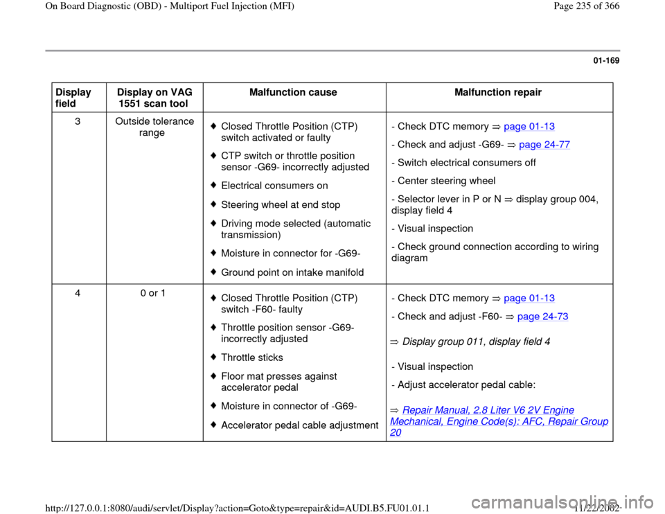
01-169
Display
field Display on VAG
1551 scan tool Malfunction cause
Malfunction repair
3 Outside tolerance
range
Closed Throttle Position (CTP)
switch activated or faulty CTP switch or throttle position
sensor -G69- incorrectly adjusted Electrical consumers onSteering wheel at end stopDriving mode selected (automatic
transmission) Moisture in connector for -G69-Ground point on intake manifold - Check DTC memory page 01
-13
- Check and adjust -G69- page 24
-77
- Switch electrical consumers off
- Center steering wheel
- Selector lever in P or N display group 004,
display field 4 - Visual inspection
- Check ground connection according to wiring
diagram
4 0 or 1
Closed Throttle Position (CTP)
switch -F60- faulty Throttle position sensor -G69-
incorrectly adjusted Throttle sticks Floor mat presses against
accelerator pedal Moisture in connector of -G69-Accelerator pedal cable adjustment Display group 011, display field 4
Repair Manual, 2.8 Liter V6 2V Engine
Mechanical, Engine Code(s): AFC, Repair Group 20
- Check DTC memory page 01
-13
- Check and adjust -F60- page 24
-73
- Visual inspection
- Adjust accelerator pedal cable:
Pa
ge 235 of 366 On Board Dia
gnostic
(OBD
) - Multi
port Fuel In
jection
(MFI
)
11/22/2002 htt
p://127.0.0.1:8080/audi/servlet/Dis
play?action=Goto&t
yp
e=re
pair&id=AUDI.B5.FU01.01.1
Page 236 of 366

Notes on display field 3:
The mechanical Closed Throttle Position (CTP) switch must be closed for the testing on the Throttle position sensor
learning values display field 4. If the displays in display fields 2 and 3 match at idle, the learning process is OK. If no learning process takes place, the
last value learned will be displayed continuously.
If engine control module is without power, the throttle position sensor learning value will be set to 0.550 V.
Pa
ge 236 of 366 On Board Dia
gnostic
(OBD
) - Multi
port Fuel In
jection
(MFI
)
11/22/2002 htt
p://127.0.0.1:8080/audi/servlet/Dis
play?action=Goto&t
yp
e=re
pair&id=AUDI.B5.FU01.01.1
Page 238 of 366
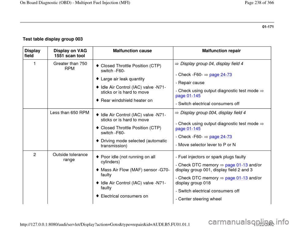
01-171
Test table display group 003 Display
field Display on VAG
1551 scan tool Malfunction cause
Malfunction repair
1 Greater than 750
RPM
Closed Throttle Position (CTP)
switch -F60- Large air leak quantity Idle Air Control (IAC) valve -N71-
sticks or is hard to move Rear windshield heater on Display group 04, display field 4
- Check -F60- page 24
-73
- Repair cause
- Check using output diagnostic test mode
page 01
-145
- Switch electrical consumers off
Less than 650 RPM
Idle Air Control (IAC) valve -N71-
sticks or is hard to move Closed Throttle Position (CTP)
switch -F60- Driving mode selected (automatic
transmission) Display group 004, display field 4
- Check using output diagnostic test mode
page 01
-145
- Check -F60- page 24
-73
- Move selector lever to P or N
2 Outside tolerance
range
Poor idle (not running on all
cylinders) Mass Air Flow (MAF) sensor -G70-
faulty Idle Air Control (IAC) valve -N71-
faulty Electrical consumers on- Fuel injectors or spark plugs faulty
- Check DTC memory page 01
-13
and/or
display group 001, display field 2 and 3
- Check DTC memory page 01
-13
and/or
display group 018
- Switch electrical consumers off
- Center steering wheel
Pa
ge 238 of 366 On Board Dia
gnostic
(OBD
) - Multi
port Fuel In
jection
(MFI
)
11/22/2002 htt
p://127.0.0.1:8080/audi/servlet/Dis
play?action=Goto&t
yp
e=re
pair&id=AUDI.B5.FU01.01.1
Page 240 of 366
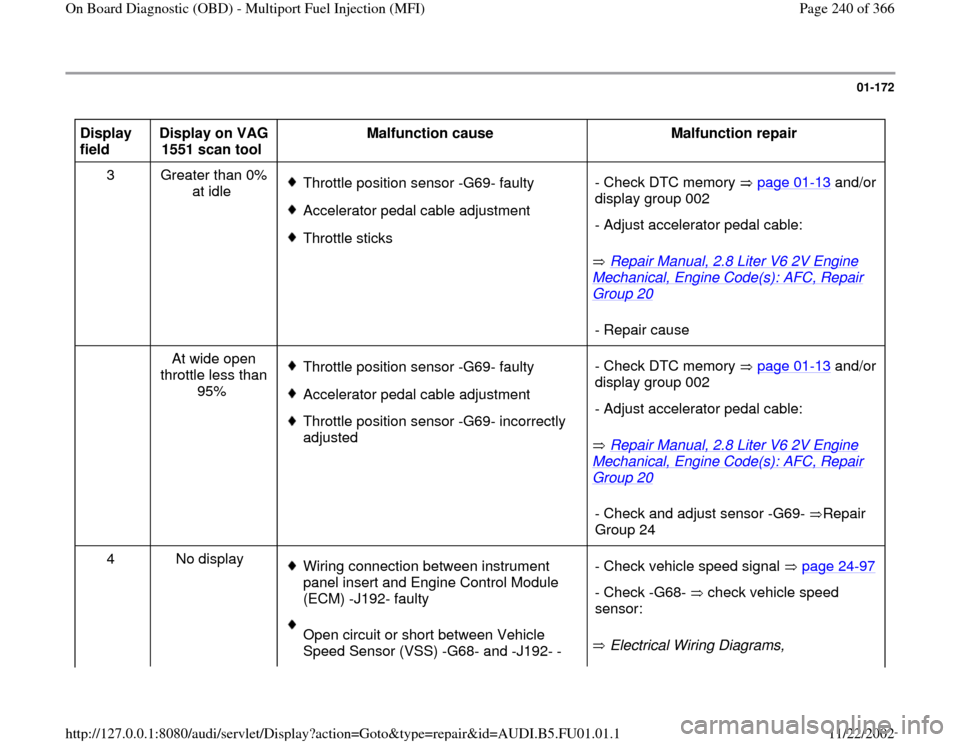
01-172
Display
field Display on VAG
1551 scan tool Malfunction cause
Malfunction repair
3 Greater than 0%
at idle
Throttle position sensor -G69- faultyAccelerator pedal cable adjustmentThrottle sticks
Repair Manual, 2.8 Liter V6 2V Engine
Mechanical, Engine Code(s): AFC, Repair Group 20
- Check DTC memory page 01
-13
and/or
display group 002
- Adjust accelerator pedal cable:- Repair cause
At wide open
throttle less than
95%
Throttle position sensor -G69- faultyAccelerator pedal cable adjustment Throttle position sensor -G69- incorrectly
adjusted
Repair Manual, 2.8 Liter V6 2V Engine
Mechanical, Engine Code(s): AFC, Repair Group 20
- Check DTC memory page 01
-13
and/or
display group 002
- Adjust accelerator pedal cable:- Check and adjust sensor -G69- Repair
Group 24
4 No display
Wiring connection between instrument
panel insert and Engine Control Module
(ECM) -J192- faulty Open circuit or short between Vehicle
Speed Sensor (VSS) -G68- and -J192- - Electrical Wiring Diagrams, - Check vehicle speed signal page 24
-97
- Check -G68- check vehicle speed
sensor:
Pa
ge 240 of 366 On Board Dia
gnostic
(OBD
) - Multi
port Fuel In
jection
(MFI
)
11/22/2002 htt
p://127.0.0.1:8080/audi/servlet/Dis
play?action=Goto&t
yp
e=re
pair&id=AUDI.B5.FU01.01.1