power AUDI A4 1995 B5 / 1.G APB Engine Ignition System Checking
[x] Cancel search | Manufacturer: AUDI, Model Year: 1995, Model line: A4, Model: AUDI A4 1995 B5 / 1.GPages: 64, PDF Size: 0.37 MB
Page 5 of 64
28-4
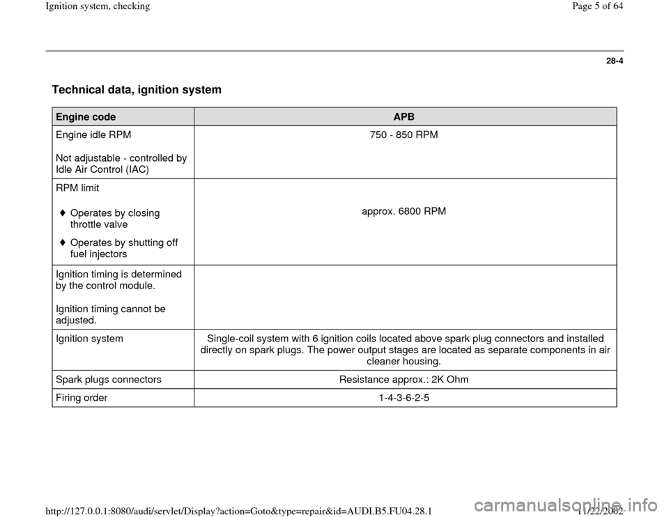
Technical data, ignition system
Engine code
APB
Engine idle RPM
Not adjustable - controlled by
Idle Air Control (IAC) 750 - 850 RPM
RPM limit
Operates by closing
throttle valve
Operates by shutting off
fuel injectors
approx. 6800 RPM
Ignition timing is determined
by the control module.
Ignition timing cannot be
adjusted.
Ignition system Single-coil system with 6 ignition coils located above spark plug connectors and installed
directly on spark plugs. The power output stages are located as separate components in air
cleaner housing.
Spark plugs connectors Resistance approx.: 2K Ohm
Firing order 1-4-3-6-2-5
Pa
ge 5 of 64 I
gnition s
ystem, checkin
g
11/22/2002 htt
p://127.0.0.1:8080/audi/servlet/Dis
play?action=Goto&t
yp
e=re
pair&id=AUDI.B5.FU04.28.1
Page 10 of 64
28-9
If the specification is not obtained:
- Check wiring.
Electrical Wiring Diagrams, Troubleshooting &
Component Locations If the specification is obtained:
- Disconnect 3-pin harness connectors on power
output stages for ignition coils; component
locations overview Page 24
-5 .
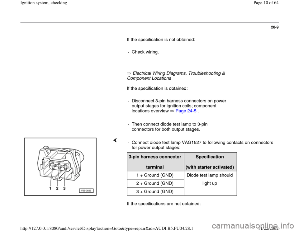
- Then connect diode test lamp to 3-pin
connectors for both output stages.
If the specifications are not obtained: - Connect diode test lamp VAG1527 to following contacts on connectors
for power output stages: 3-pin harness connector
terminal
Specification
(with starter activated)
1 + Ground (GND) Diode test lamp should
2 + Ground (GND) light up
3 + Ground (GND)
Pa
ge 10 of 64 I
gnition s
ystem, checkin
g
11/22/2002 htt
p://127.0.0.1:8080/audi/servlet/Dis
play?action=Goto&t
yp
e=re
pair&id=AUDI.B5.FU04.28.1
Page 12 of 64

28-10
Check the following wiring connections for open circuits and/or short to B+
or Ground (GND).
Black 3-pin connector on power
output stage, terminal
3-pin connector on ignition
coil, terminal
1 1 (cylinder 1)
2 1 (cylinder 2)
3 1 (cylinder 3)
Brown 3-pin connector on power
output stage, terminal
3-pin connector on ignition
coil, terminal
1 1 (cylinder 4)
2 1 (cylinder 5)
3 1 (cylinder 6)
- Eliminate any open/short circuit as necessary.
Pa
ge 12 of 64 I
gnition s
ystem, checkin
g
11/22/2002 htt
p://127.0.0.1:8080/audi/servlet/Dis
play?action=Goto&t
yp
e=re
pair&id=AUDI.B5.FU04.28.1
Page 13 of 64
28-11
Power output stages for ignition coils,
checking
Note:
Power Output Stage -N122 (black connector)
activates the ignition coils for cylinder bank 1
(cylinders 1 to 3).
Power Output Stage 2 -N192 (brown connector)
activates the ignition coils for cylinder bank 2
(cylinders 4 to 6).
Checking activation of power output stages
- Disconnect harness connectors from all six fuel
injectors.
Note:
It is important to ensure that no fuel is injected
during the test as this would damage the catalytic
converter. The harness connectors on the fuel
injectors must therefore be disconnected.
Pa
ge 13 of 64 I
gnition s
ystem, checkin
g
11/22/2002 htt
p://127.0.0.1:8080/audi/servlet/Dis
play?action=Goto&t
yp
e=re
pair&id=AUDI.B5.FU04.28.1
Page 14 of 64
28-12
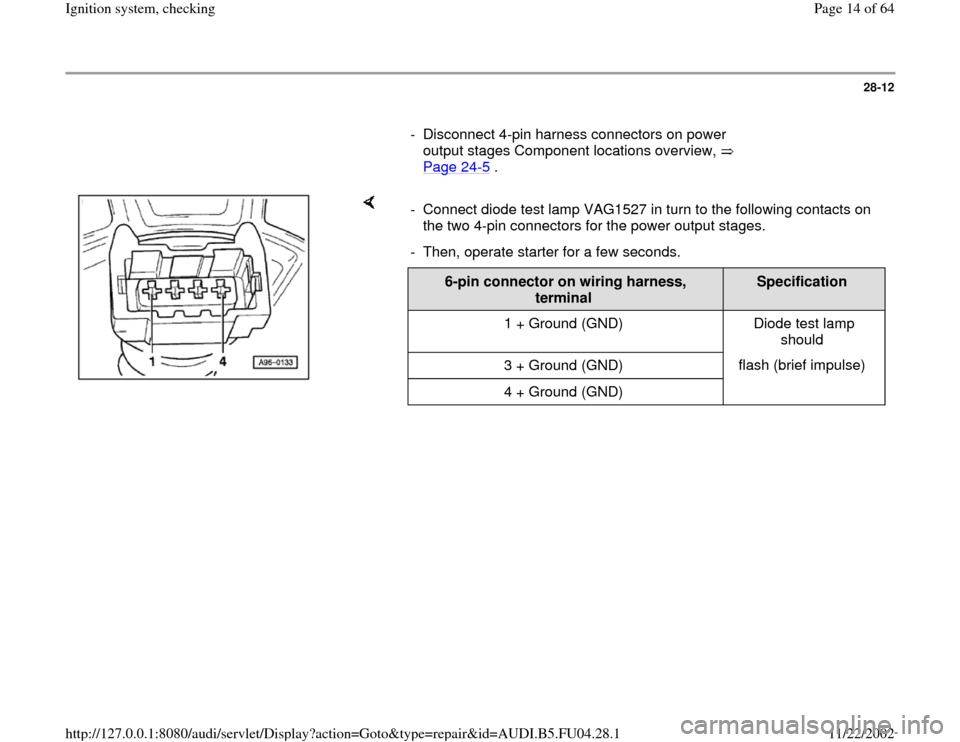
- Disconnect 4-pin harness connectors on power
output stages Component locations overview,
Page 24
-5 .
- Connect diode test lamp VAG1527 in turn to the following contacts on
the two 4-pin connectors for the power output stages.
- Then, operate starter for a few seconds.
6-pin connector on wiring harness,
terminal
Specification
1 + Ground (GND) Diode test lamp
should
3 + Ground (GND) flash (brief impulse)
4 + Ground (GND)
Pa
ge 14 of 64 I
gnition s
ystem, checkin
g
11/22/2002 htt
p://127.0.0.1:8080/audi/servlet/Dis
play?action=Goto&t
yp
e=re
pair&id=AUDI.B5.FU04.28.1
Page 16 of 64

28-14
- Rectify any open/short circuit as necessary.
If no wiring malfunction is detected:
- Connect 4-pin connectors to power output
stages.
- Disconnect 3-pin connectors from power output
stages.
- Connect diode test lamp VAG1527 to battery
(B+) and to one of the 3 terminals on power
output stage.
- Operate starter for few seconds.
The diode test lamp should flash.
- Carry out test with all 3 terminals on each of the
3-pin connectors for the power output stages.
The diode test lamp should flash each time.
Pa
ge 16 of 64 I
gnition s
ystem, checkin
g
11/22/2002 htt
p://127.0.0.1:8080/audi/servlet/Dis
play?action=Goto&t
yp
e=re
pair&id=AUDI.B5.FU04.28.1
Page 17 of 64

28-15
If the diode test lamp does not flash when testing
one or more of the contacts:
Check the Ground (GND) connections for the
power output stages as follows:
- Disconnect 4-pin harness connectors from
power output stages.
- Connect diode test lamp VAG1527 to battery
(B+) and terminal 2 of each of the 4-pin
connectors in turn.
The diode test lamp should light up.
Pa
ge 17 of 64 I
gnition s
ystem, checkin
g
11/22/2002 htt
p://127.0.0.1:8080/audi/servlet/Dis
play?action=Goto&t
yp
e=re
pair&id=AUDI.B5.FU04.28.1
Page 18 of 64
28-16
- If diode test lamp does not light up, test for open
circuit in wiring using wiring diagram.
Electrical Wiring Diagrams, Troubleshooting &
Component Locations
If the diode test lamp lights up:
- Replace power output stage.
Note:
Before installing new power output stage coat
metal side with heat paste (part no. G 052 170
A1). The heat paste is used to prevent corrosion
between the power output stage and the
fastening point, it is also used to transfer heat
from the power output stage.
CAUTION!
Part numbers are only for reference, always
check with your parts department for latest
information.
Pa
ge 18 of 64 I
gnition s
ystem, checkin
g
11/22/2002 htt
p://127.0.0.1:8080/audi/servlet/Dis
play?action=Goto&t
yp
e=re
pair&id=AUDI.B5.FU04.28.1
Page 61 of 64

28-54
Evaluation display group 014, display field 3 Display field:
3
Possible cause
Corrective action
greater 15
Spark plug faulty
Spark plug connector faulty
Ignition coil or power output stage faulty- Check spark plug and ignition cable with
connector
- Check ignition coil Page 28
-5 .
- Check power output stages Page 28
-11
Fuel injector faulty
Check compression of one or more cylinder
weak - Check fuel injectors Page 24
-39
- Check compression pressure
Pa
ge 61 of 64 I
gnition s
ystem, checkin
g
11/22/2002 htt
p://127.0.0.1:8080/audi/servlet/Dis
play?action=Goto&t
yp
e=re
pair&id=AUDI.B5.FU04.28.1
Page 64 of 64

28-57
Evaluation display groups 015 and 016 Display field: 1,2 and 3 from measuring
value block 15 and 16
Possible cause
Corrective action
greater 15
Spark plug faultySpark plug connector faulty Ignition coil or power output stage
faulty - Check spark plug and ignition
cable with connector
- Check ignition coil Page 28
-5 .
- Check power output stages
Page 28
-11
Fuel injector faultyCheck compression of one or
more cylinder weak - Check fuel injectors Page 24
-39
- Check compression pressure
Pa
ge 64 of 64 I
gnition s
ystem, checkin
g
11/22/2002 htt
p://127.0.0.1:8080/audi/servlet/Dis
play?action=Goto&t
yp
e=re
pair&id=AUDI.B5.FU04.28.1