OBD port AUDI A4 1995 B5 / 1.G APB Engine Motronic Syst
[x] Cancel search | Manufacturer: AUDI, Model Year: 1995, Model line: A4, Model: AUDI A4 1995 B5 / 1.GPages: 166, PDF Size: 0.53 MB
Page 1 of 166
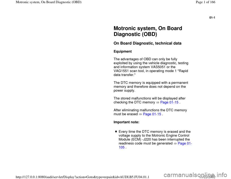
01-1
Motronic system, On Board
Diagnostic (OBD)
On Board Diagnostic, technical data
Equipment
The advantages of OBD can only be fully
exploited by using the vehicle diagnostic, testing
and information system VAS5051 or the
VAG1551 scan tool, in operating mode 1 "Rapid
data transfer."
The DTC memory is equipped with a permanent
memory and therefore does not depend on the
power supply.
The stored malfunctions will be displayed after
checking the DTC memory Page 01
-15
.
After eliminating malfunctions the DTC memory
must be erased Page 01
-15
.
Important note:
Every time the DTC memory is erased and the
voltage supply to the Motronic Engine Control
Module (ECM) -J220 has been interrupted the
readiness code must be generated Page 01
-
105
.
Pa
ge 1 of 166 Motronic s
ystem, On Board Dia
gnostic
(OBD
)
11/22/2002 htt
p://127.0.0.1:8080/audi/servlet/Dis
play?action=Goto&t
yp
e=re
pair&id=AUDI.B5.FU04.01.1
Page 3 of 166
01-3
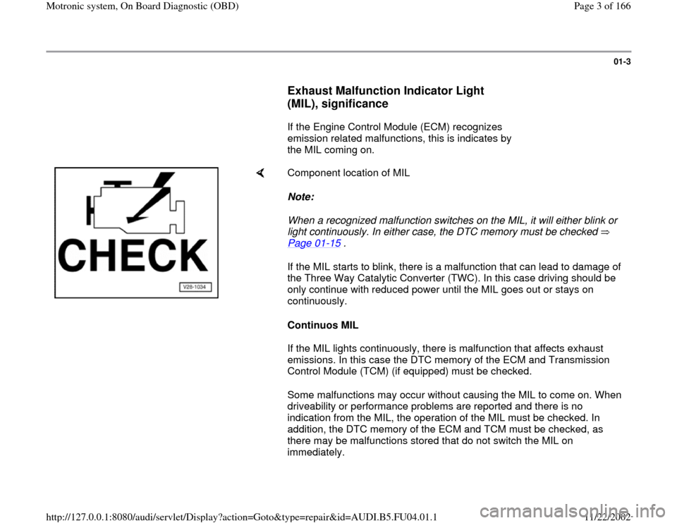
Exhaust Malfunction Indicator Light
(MIL), significance
If the Engine Control Module (ECM) recognizes
emission related malfunctions, this is indicates by
the MIL coming on.
Component location of MIL
Note:
When a recognized malfunction switches on the MIL, it will either blink or
light continuously. In either case, the DTC memory must be checked
Page 01
-15
.
If the MIL starts to blink, there is a malfunction that can lead to damage of
the Three Way Catalytic Converter (TWC). In this case driving should be
only continue with reduced power until the MIL goes out or stays on
continuously.
Continuos MIL
If the MIL lights continuously, there is malfunction that affects exhaust
emissions. In this case the DTC memory of the ECM and Transmission
Control Module (TCM) (if equipped) must be checked.
Some malfunctions may occur without causing the MIL to come on. When
driveability or performance problems are reported and there is no
indication from the MIL, the operation of the MIL must be checked. In
addition, the DTC memory of the ECM and TCM must be checked, as
there may be malfunctions stored that do not switch the MIL on
immediately.
Pa
ge 3 of 166 Motronic s
ystem, On Board Dia
gnostic
(OBD
)
11/22/2002 htt
p://127.0.0.1:8080/audi/servlet/Dis
play?action=Goto&t
yp
e=re
pair&id=AUDI.B5.FU04.01.1
Page 22 of 166
01-19
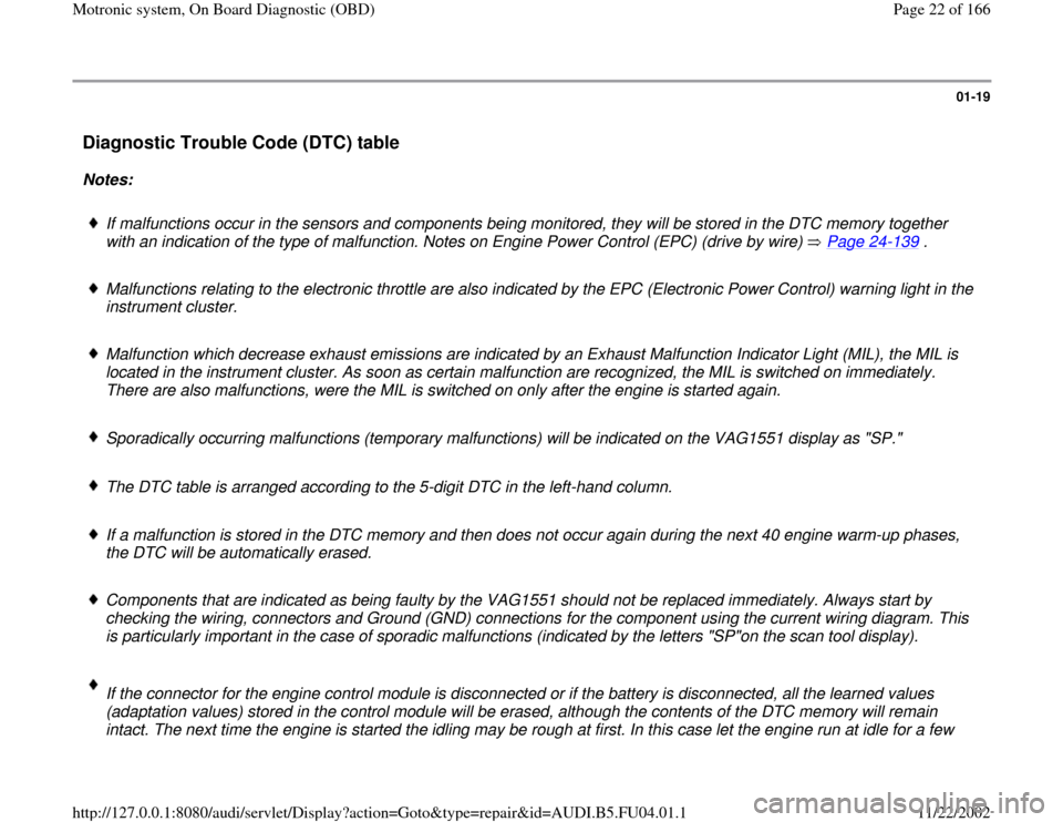
Diagnostic Trouble Code (DTC) table
Notes:
If malfunctions occur in the sensors and components being monitored, they will be stored in the DTC memory together
with an indication of the type of malfunction. Notes on Engine Power Control (EPC) (drive by wire) Page 24
-139
.
Malfunctions relating to the electronic throttle are also indicated by the EPC (Electronic Power Control) warning light in the
instrument cluster.
Malfunction which decrease exhaust emissions are indicated by an Exhaust Malfunction Indicator Light (MIL), the MIL is
located in the instrument cluster. As soon as certain malfunction are recognized, the MIL is switched on immediately.
There are also malfunctions, were the MIL is switched on only after the engine is started again.
Sporadically occurring malfunctions (temporary malfunctions) will be indicated on the VAG1551 display as "SP."
The DTC table is arranged according to the 5-digit DTC in the left-hand column.
If a malfunction is stored in the DTC memory and then does not occur again during the next 40 engine warm-up phases,
the DTC will be automatically erased.
Components that are indicated as being faulty by the VAG1551 should not be replaced immediately. Always start by
checking the wiring, connectors and Ground (GND) connections for the component using the current wiring diagram. This
is particularly important in the case of sporadic malfunctions (indicated by the letters "SP"on the scan tool display).
If the connector for the engine control module is disconnected or if the battery is disconnected, all the learned values
(adaptation values) stored in the control module will be erased, although the contents of the DTC memory will remain
intact. The next time the engine is started the idling may be rough at first. In this case let the engine run at idle for a few
Pa
ge 22 of 166 Motronic s
ystem, On Board Dia
gnostic
(OBD
)
11/22/2002 htt
p://127.0.0.1:8080/audi/servlet/Dis
play?action=Goto&t
yp
e=re
pair&id=AUDI.B5.FU04.01.1
Page 35 of 166
01-29
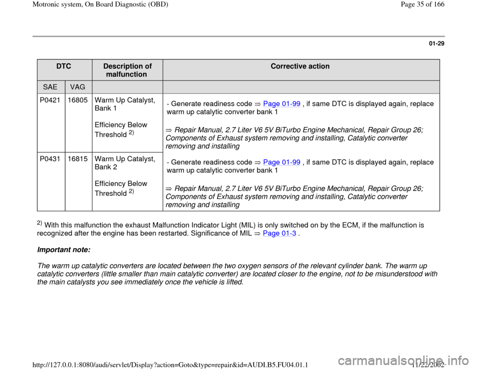
DTC
Description of
malfunction
Corrective action
SAE
VAG
P0421 16805 Warm Up Catalyst,
Bank 1
Efficiency Below
Threshold
2) Repair Manual, 2.7 Liter V6 5V BiTurbo Engine Mechanical, Repair Group 26;
Components of Exhaust system removing and installing, Catalytic converter
removing and installing - Generate readiness code Page 01
-99
, if same DTC is displayed again, replace
warm up catalytic converter bank 1
P0431 16815 Warm Up Catalyst,
Bank 2
Efficiency Below
Threshold
2) Repair Manual, 2.7 Liter V6 5V BiTurbo Engine Mechanical, Repair Group 26;
Components of Exhaust system removing and installing, Catalytic converter
removing and installing - Generate readiness code Page 01
-99
, if same DTC is displayed again, replace
warm up catalytic converter bank 1
2) With this malfunction the exhaust Malfunction Indicator Light (MIL) is only switched on by the ECM, if the malfunction is
recognized after the engine has been restarted. Significance of MIL Page 01
-3 .
Important note:
The warm up catalytic converters are located between the two oxygen sensors of the relevant cylinder bank. The warm up
catalytic converters (little smaller than main catalytic converter) are located closer to the engine, not to be misunderstood with
the main catalysts you see immediately once the vehicle is lifted.
Pa
ge 35 of 166 Motronic s
ystem, On Board Dia
gnostic
(OBD
)
11/22/2002 htt
p://127.0.0.1:8080/audi/servlet/Dis
play?action=Goto&t
yp
e=re
pair&id=AUDI.B5.FU04.01.1
Page 131 of 166

01-109
Display fields
1 2 3 4
Display group 060: Adaptation of throttle valve control module
Display xx % xx %
x
---
Indicated Throttle
valve angle
(angle
sensor 1) Throttle
valve angle
(angle
sensor 2) Adaptation step counter
Adaptation condition
Work area 0 - 100 % 0 - 100 %
0 - 8
ADP. runs
ADP. OK
ADP. ERROR
Specified
value 3 - 93 % 97 - 3 %
8
ADP. OK
Note:
During adaptation, adaptation step counter
must reach the number 8. (Some numbers
may be skipped). If "ADP. ERROR." is displayed:
Check DTC memory Page
01
-15
.
If specified value is not
obtained: Note, Page Page
24
-152
.
Note for display field 3:
During adaptation different digits are displayed in display field 3, which indicate the particular adaptation condition. It is not
important what the adaptation step counter (display field 3) displays during adaptation, rather that display field 4 displays the
Pa
ge 131 of 166 Motronic s
ystem, On Board Dia
gnostic
(OBD
)
11/22/2002 htt
p://127.0.0.1:8080/audi/servlet/Dis
play?action=Goto&t
yp
e=re
pair&id=AUDI.B5.FU04.01.1
Page 142 of 166
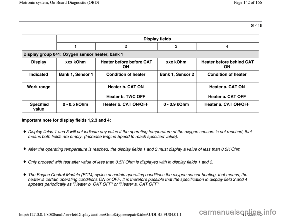
01-118
Display fields
1 2 3 4
Display group 041: Oxygen sensor heater, bank 1
Display
xxx kOhm
Heater before before CAT
ON xxx kOhm
Heater before behind CAT
ON
Indicated
Bank 1, Sensor 1
Condition of heater
Bank 1, Sensor 2
Condition of heater
Work range
Heater b. CAT ON
Heater b. TWC OFF
Heater a. CAT ON
Heater a. CAT OFF
Specified
value 0 - 0.5 kOhm
Heater b. CAT ON/OFF
0 - 0.9 kOhm
Heater a. CAT ON/OFF Important note for display fields 1,2,3 and 4:
Display fields 1 and 3 will not indicate any value if the operating temperature of the oxygen sensors is not reached, that
means both fields are empty. (Increase Engine Speed to reach specified value).
After the operating temperature is reached, the display fields 1 and 3 must display a value of less than 0.5K Ohm
Only proceed with test after value of less than 0.5K Ohm is displayed with in display fields 1 and 3.
The Engine Control Module (ECM) cycles at certain operating conditions the oxygen sensor heating, that means, the
heater is certain operating conditions ON or OFF. It is therefore possible that the specification in display field 2 and 4
appears periodically as "Heater b. CAT OFF" or "Heater a. CAT OFF"
Pa
ge 142 of 166 Motronic s
ystem, On Board Dia
gnostic
(OBD
)
11/22/2002 htt
p://127.0.0.1:8080/audi/servlet/Dis
play?action=Goto&t
yp
e=re
pair&id=AUDI.B5.FU04.01.1
Page 144 of 166

01-119
Display fields
1 2 3 4
Display group 042: Oxygen sensor heater, bank 1
Display
xxx kOhm
Heater before before CAT
ON xxx kOhm
Heater before behind CAT
ON
Indicated
Bank 1, Sensor 1
Condition of heater
Bank 1, Sensor 2
Condition of heater
Work range
Heater b. CAT ON
Heater b. TWC OFF
Heater a. CAT ON
Heater a. CAT OFF
Specified
value 0 - 0.5 kOhm
Heater b. CAT ON/OFF
0 - 0.9 kOhm
Heater a. CAT ON/OFF
Note
Observe note
below
Observe note
below Important note for display fields 1,2,3 and 4:
Display fields 1 and 3 will not indicate any value if the operating temperature of the oxygen sensors is not reached, that
means both fields are empty. (Increase Engine Speed to reach specified value).
After the operating temperature is reached, the display fields 1 and 3 must display a value of less than 0.5K Ohm
Only proceed with test after value of less than 0.5K Ohm is displayed with in display fields 1 and 3.
Pa
ge 144 of 166 Motronic s
ystem, On Board Dia
gnostic
(OBD
)
11/22/2002 htt
p://127.0.0.1:8080/audi/servlet/Dis
play?action=Goto&t
yp
e=re
pair&id=AUDI.B5.FU04.01.1