light AUDI A4 1995 B5 / 1.G ATQ Engine Additional Signals Testing Workshop Manual
[x] Cancel search | Manufacturer: AUDI, Model Year: 1995, Model line: A4, Model: AUDI A4 1995 B5 / 1.GPages: 44, PDF Size: 0.19 MB
Page 16 of 44
24-178
Brake light switch and brake pedal
switch, checking
Note:
For safety reasons, the instruction from the
accelerator pedal sensor (potentiometer) to the
ECM to open the throttle valve is suppressed
when brake is being operated. This requires the
brake light switch signal and also the brake pedal
switch signal in the control module.
If brake pedal is operated with accelerator pedal
constantly depressed, engine is immediately
regulated down to idle speed. A faulty switch can
lead to undesired regulation.
Test sequence
- Connect VAS5051 tester or VAG1551 scan tool
and select the control module for engine
electronics using "address word" 01 Page 01
-
9 .
Ignition must remain switched on for this.Rapid data transfer
HELP
Select function XX
When indicated on display:
- Press buttons -0- and -8- to select "Read Measuring Value Block" and
press -Q- button to confirm input.
Pa
ge 16 of 44 Additional si
gnals, testin
g
11/23/2002 htt
p://127.0.0.1:8080/audi/servlet/Dis
play?action=Goto&t
yp
e=re
pair&id=AUDI.B5.FU05.24.6
Page 17 of 44
24-179
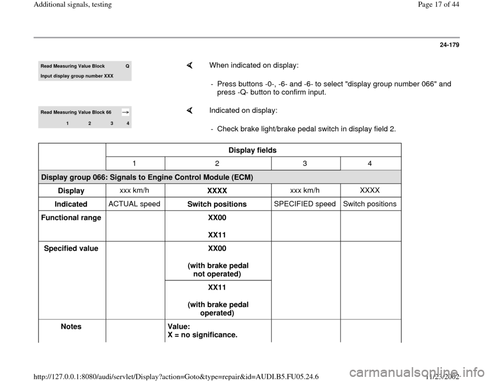
Read Measurin
g Value Block
Q
Input display group number XXX
When indicated on display:
- Press buttons -0-, -6- and -6- to select "display group number 066" and
press -Q- button to confirm input.
Read Measuring Value Block 66
1
2
3
4
Indicated on display:
- Check brake light/brake pedal switch in display field 2.
Display fields
1 2 3 4
Display group 066: Signals to Engine Control Module (ECM)
Display xxx km/h
XXXX xxx km/h XXXX
Indicated ACTUAL speed
Switch positions SPECIFIED speed Switch positions
Functional range
XX00
XX11
Specified value
XX00
(with brake pedal
not operated)
XX11
(with brake pedal
operated)
Notes
Value:
X = no significance.
Pa
ge 17 of 44 Additional si
gnals, testin
g
11/23/2002 htt
p://127.0.0.1:8080/audi/servlet/Dis
play?action=Goto&t
yp
e=re
pair&id=AUDI.B5.FU05.24.6
Page 18 of 44
Switch points slightly offset
Pa
ge 18 of 44 Additional si
gnals, testin
g
11/23/2002 htt
p://127.0.0.1:8080/audi/servlet/Dis
play?action=Goto&t
yp
e=re
pair&id=AUDI.B5.FU05.24.6
Page 19 of 44
24-180
If indications do not resemble description:
Check switch
- Remove driver-side storage compartment.
Repair Manual, Body
-Interior, Repair Group
68; Instrument Panel; Removing Driver
-Side
Storage Compartment
- Disconnect harness connector at brake light
switch and brake pedal switch.
Note:
Connector sockets are marked on the back side
of the connector.
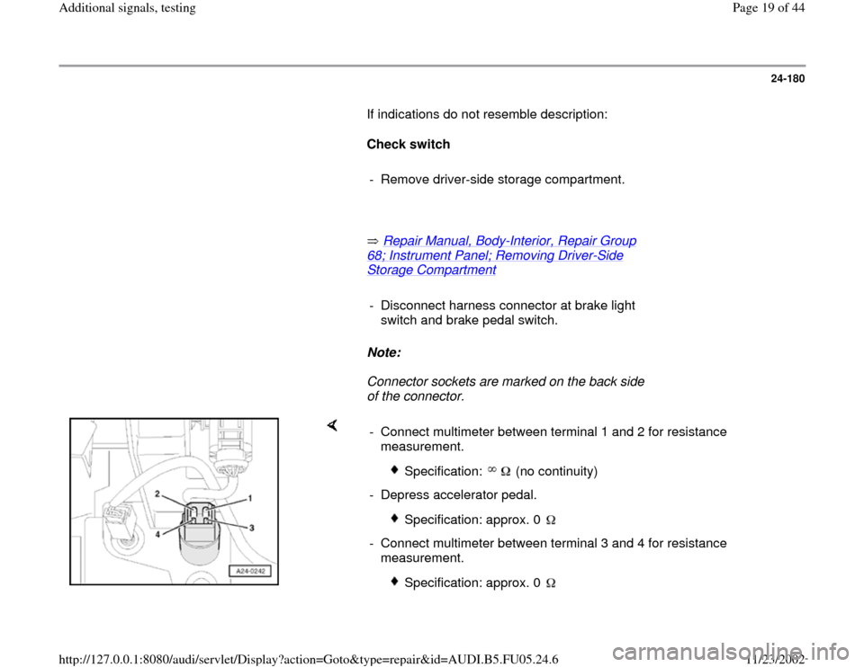
- Connect multimeter between terminal 1 and 2 for resistance
measurement.
Specification: (no continuity)
- Depress accelerator pedal.
Specification: approx. 0
- Connect multimeter between terminal 3 and 4 for resistance
measurement.
Specification: approx. 0
Pa
ge 19 of 44 Additional si
gnals, testin
g
11/23/2002 htt
p://127.0.0.1:8080/audi/servlet/Dis
play?action=Goto&t
yp
e=re
pair&id=AUDI.B5.FU05.24.6
Page 21 of 44
24-181
If specified values are not obtained:
- Check adjustment of switch or
- Replace brake light switch / brake pedal
switch.
If specified values are obtained:
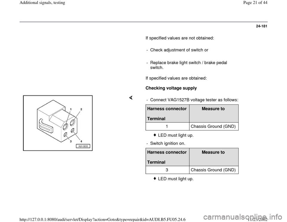
Checking voltage supply
- Connect VAG1527B voltage tester as follows:Harness connector
Terminal
Measure to
1 Chassis Ground (GND)
LED must light up.
- Switch ignition on.
Harness connector
Terminal
Measure to
3 Chassis Ground (GND)
LED must light up.
Pa
ge 21 of 44 Additional si
gnals, testin
g
11/23/2002 htt
p://127.0.0.1:8080/audi/servlet/Dis
play?action=Goto&t
yp
e=re
pair&id=AUDI.B5.FU05.24.6
Page 22 of 44
24-182
If LED does not light up:
- Check wire connection from terminal 1 or 3 of
connector for open circuit and short circuit to
Ground (GND):
Electrical Wiring Diagrams, Troubleshooting &
Component Locations binder
- Repair open circuit or short circuit if
necessary.
If LED lights up:
Checking activation
- Connect VAG1598/31 test box at wiring harness
to ECM, do not connect ECM Page 24
-17
.
- Check the following wire connections for open
circuit and short circuit to Ground (GND) and B+:
Harness connector
Terminal
VAG1598/31 test box
Socket
2 56
4 55
Pa
ge 22 of 44 Additional si
gnals, testin
g
11/23/2002 htt
p://127.0.0.1:8080/audi/servlet/Dis
play?action=Goto&t
yp
e=re
pair&id=AUDI.B5.FU05.24.6
Page 29 of 44
24-186
If specified value is obtained:
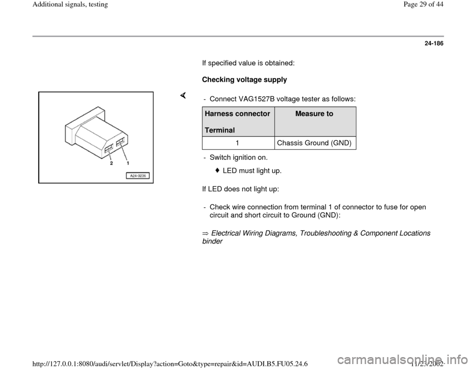
Checking voltage supply
If LED does not light up:
Electrical Wiring Diagrams, Troubleshooting & Component Locations
binder - Connect VAG1527B voltage tester as follows:Harness connector
Terminal
Measure to
1 Chassis Ground (GND)
- Switch ignition on.
LED must light up.
- Check wire connection from terminal 1 of connector to fuse for open
circuit and short circuit to Ground (GND):
Pa
ge 29 of 44 Additional si
gnals, testin
g
11/23/2002 htt
p://127.0.0.1:8080/audi/servlet/Dis
play?action=Goto&t
yp
e=re
pair&id=AUDI.B5.FU05.24.6
Page 30 of 44
24-187
If LED lights up:
Checking activation
- Connect VAG1598/31 test box at wiring harness
to ECM, do not connect ECM Page 24
-17
.
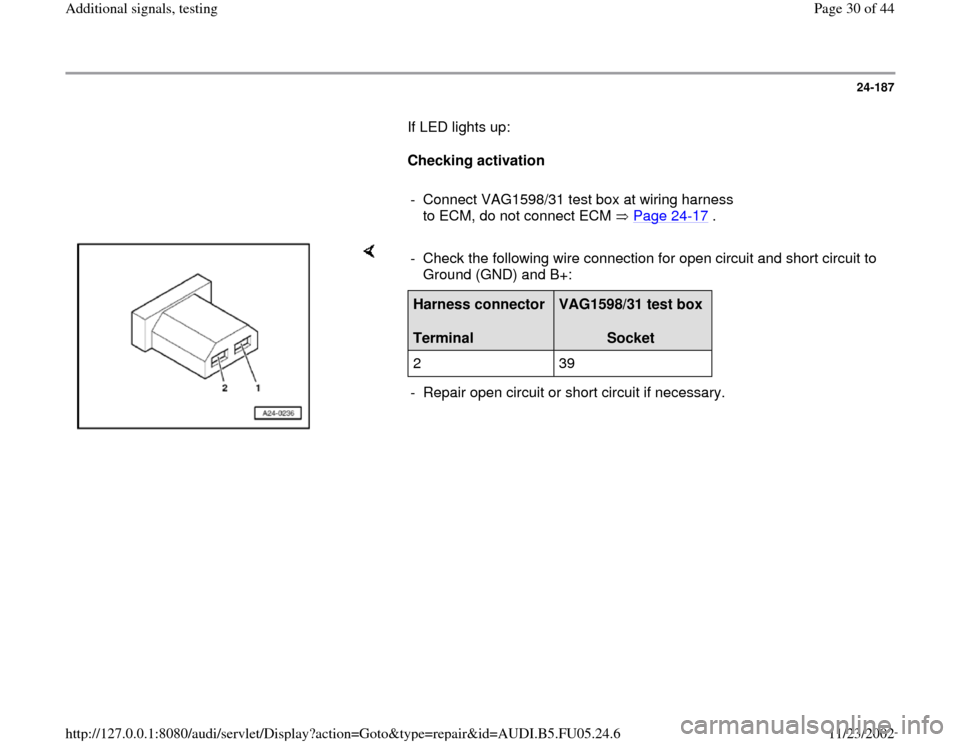
- Check the following wire connection for open circuit and short circuit to
Ground (GND) and B+: Harness connector
Terminal
VAG1598/31 test box
Socket
2 39
- Repair open circuit or short circuit if necessary.
Pa
ge 30 of 44 Additional si
gnals, testin
g
11/23/2002 htt
p://127.0.0.1:8080/audi/servlet/Dis
play?action=Goto&t
yp
e=re
pair&id=AUDI.B5.FU05.24.6