AUDI A4 1995 B5 / 1.G ATQ Engine Electronic Engine Power Control Checking Owner's Manual
Manufacturer: AUDI, Model Year: 1995, Model line: A4, Model: AUDI A4 1995 B5 / 1.GPages: 41, PDF Size: 0.21 MB
Page 21 of 41
24-148
Angle sensor -1- for throttle drive,
checking
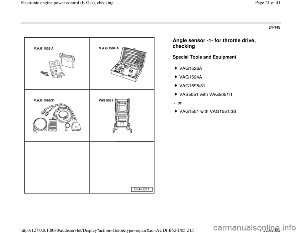
Special Tools and Equipment
VAG1526A
VAG1594A
VAG1598/31
VAS5051 with VAG5051/1
- or
VAG1551 with VAG1551/3B
Pa
ge 21 of 41 Electronic en
gine
power control
(E-Gas
), checkin
g
11/23/2002 htt
p://127.0.0.1:8080/audi/servlet/Dis
play?action=Goto&t
yp
e=re
pair&id=AUDI.B5.FU05.24.5
Page 22 of 41
24-149
Angle sensor 1 for throttle drive (power
accelerator actuation) -G187- and angle sensor 1
for throttle drive (power accelerator actuation) -
G188- inform the Engine Control Module (ECM)
about the position of the throttle valve. Both
angle sensors are located in the throttle valve
control module.
Test sequence
- Connect VAS5051 tester or VAG1551 scan tool
and select the control module for engine
electronics using "address word" 01 Page 01
-
9 .
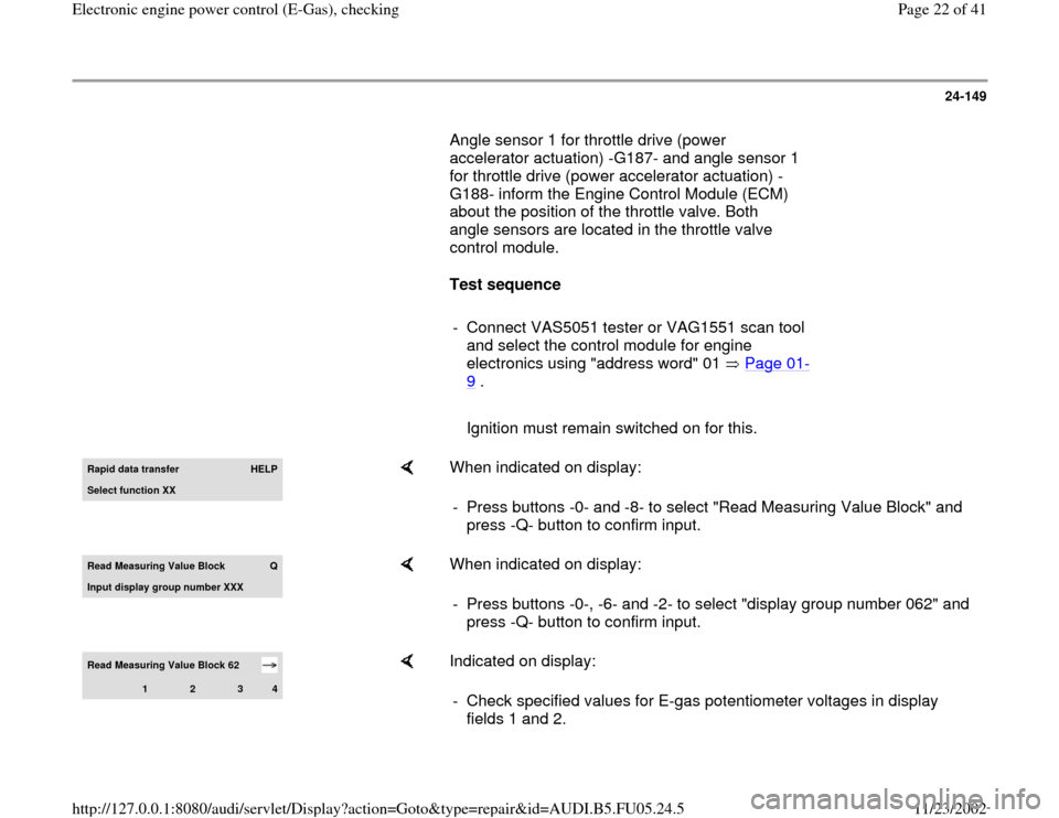
Ignition must remain switched on for this.Rapid data transfer
HELP
Select function XX
When indicated on display:
- Press buttons -0- and -8- to select "Read Measuring Value Block" and
press -Q- button to confirm input.
Read Measuring Value Block
Q
Input displa
y group number XXX
When indicated on display:
- Press buttons -0-, -6- and -2- to select "display group number 062" and
press -Q- button to confirm input.
Read Measuring Value Block 62
1
2
3
4
Indicated on display:
- Check specified values for E-gas potentiometer voltages in display
fields 1 and 2.
Pa
ge 22 of 41 Electronic en
gine
power control
(E-Gas
), checkin
g
11/23/2002 htt
p://127.0.0.1:8080/audi/servlet/Dis
play?action=Goto&t
yp
e=re
pair&id=AUDI.B5.FU05.24.5
Page 23 of 41
24-150
Display fields
1 2 3 4
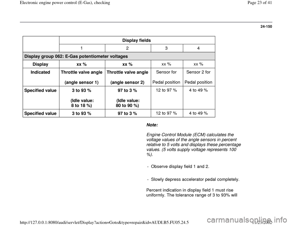
Display group 062: E-Gas potentiometer voltages
Display
xx %
xx % xx % xx %
Indicated
Throttle valve angle
(angle sensor 1) Throttle valve angle
(angle sensor 2) Sensor for
Pedal position Sensor 2 for
Pedal position
Specified value
3 to 93 %
(Idle value:
8 to 18 %) 97 to 3 %
(Idle value:
80 to 90 %) 12 to 97 % 4 to 49 %
Specified value
3 to 93 %
97 to 3 % 12 to 97 % 4 to 49 %
Note:
Engine Control Module (ECM) calculates the
voltage values of the angle sensors in percent
relative to 5 volts and displays these percentage
values. (5 volts supply voltage represents 100
%).
- Observe display field 1 and 2.
- Slowly depress accelerator pedal completely.
Percent indication in display field 1 must rise
uniformly. The tolerance range of 3 to 93% will
Pa
ge 23 of 41 Electronic en
gine
power control
(E-Gas
), checkin
g
11/23/2002 htt
p://127.0.0.1:8080/audi/servlet/Dis
play?action=Goto&t
yp
e=re
pair&id=AUDI.B5.FU05.24.5
Page 24 of 41
not be used completely during this.
Percent indication in display field 2 must
decrease uniformly. The tolerance range of 97 to
3% will not be used completely during this.
Pa
ge 24 of 41 Electronic en
gine
power control
(E-Gas
), checkin
g
11/23/2002 htt
p://127.0.0.1:8080/audi/servlet/Dis
play?action=Goto&t
yp
e=re
pair&id=AUDI.B5.FU05.24.5
Page 25 of 41
24-151
Notes:
The reason why the value indicated in display
field 1 climbs, while the value indicated in
display field 2 decreases, has to do with the fact
that the potentiometers (angle sensors) in the
throttle valve control unit run in opposite
directions.
This means that the voltage tap of angle sensor
1 runs from 0 to 5 volts. (The more the throttle
valve is opened, the larger the voltage; percent
indication climbs).
The voltage tap of angle sensor 2 runs from 5
to 0 volts. (The more the throttle valve is
opened, the lower the voltage; the percentage
decreases).
If indications do not resemble description:
- Check voltage supply and wire connections of
throttle valve control module Page 24
-152
.
Pay particular attention to harness connectors
that could be loose or corroded.
- Check accelerator pedal position sensor Page
24
-154
.
Pa
ge 25 of 41 Electronic en
gine
power control
(E-Gas
), checkin
g
11/23/2002 htt
p://127.0.0.1:8080/audi/servlet/Dis
play?action=Goto&t
yp
e=re
pair&id=AUDI.B5.FU05.24.5
Page 26 of 41
24-152
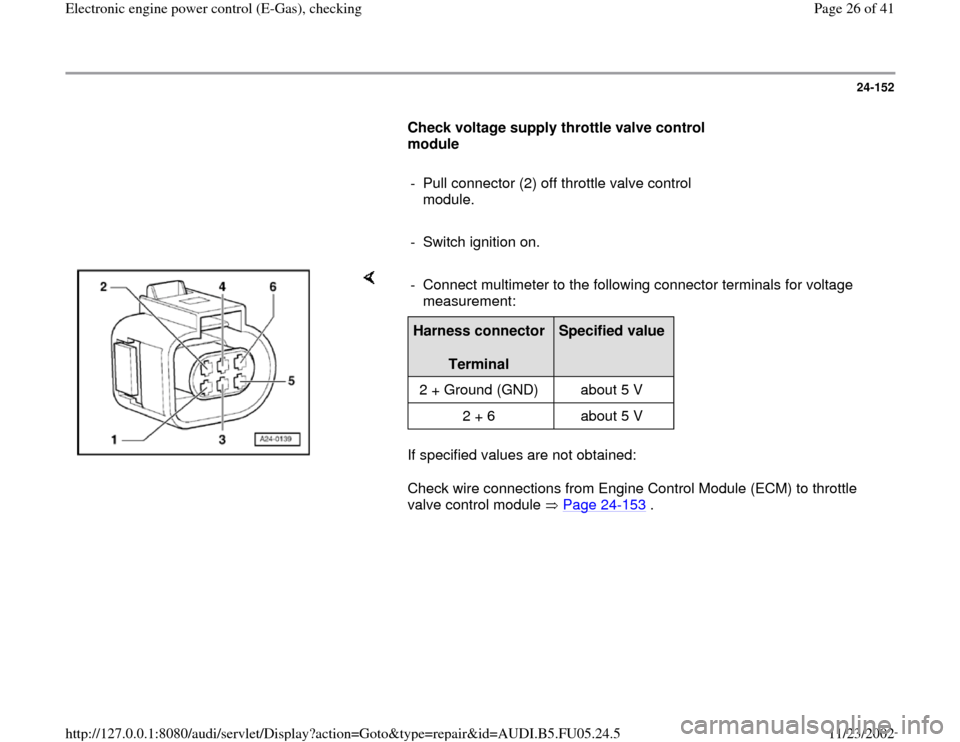
Check voltage supply throttle valve control
module
- Pull connector (2) off throttle valve control
module.
- Switch ignition on.
If specified values are not obtained:
Check wire connections from Engine Control Module (ECM) to throttle
valve control module Page 24
-153
. - Connect multimeter to the following connector terminals for voltage
measurement:
Harness connector
Terminal
Specified value
2 + Ground (GND) about 5 V
2 + 6 about 5 V
Pa
ge 26 of 41 Electronic en
gine
power control
(E-Gas
), checkin
g
11/23/2002 htt
p://127.0.0.1:8080/audi/servlet/Dis
play?action=Goto&t
yp
e=re
pair&id=AUDI.B5.FU05.24.5
Page 27 of 41
24-153
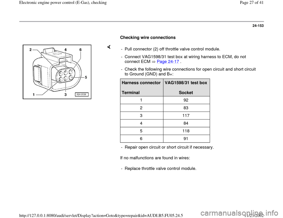
Checking wire connections
If no malfunctions are found in wires: - Pull connector (2) off throttle valve control module.
- Connect VAG1598/31 test box at wiring harness to ECM, do not
connect ECM Page 24
-17
.
- Check the following wire connections for open circuit and short circuit
to Ground (GND) and B+: Harness connector
Terminal
VAG1598/31 test box
Socket
1 92
2 83
3 117
4 84
5 118
6 91
- Repair open circuit or short circuit if necessary.
- Replace throttle valve control module.
Pa
ge 27 of 41 Electronic en
gine
power control
(E-Gas
), checkin
g
11/23/2002 htt
p://127.0.0.1:8080/audi/servlet/Dis
play?action=Goto&t
yp
e=re
pair&id=AUDI.B5.FU05.24.5
Page 28 of 41
24-154
Throttle Position (TP) sensor, checking
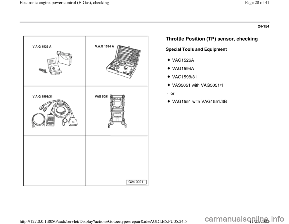
Special Tools and Equipment
VAG1526A
VAG1594A
VAG1598/31
VAS5051 with VAG5051/1
- or
VAG1551 with VAG1551/3B
Pa
ge 28 of 41 Electronic en
gine
power control
(E-Gas
), checkin
g
11/23/2002 htt
p://127.0.0.1:8080/audi/servlet/Dis
play?action=Goto&t
yp
e=re
pair&id=AUDI.B5.FU05.24.5
Page 29 of 41
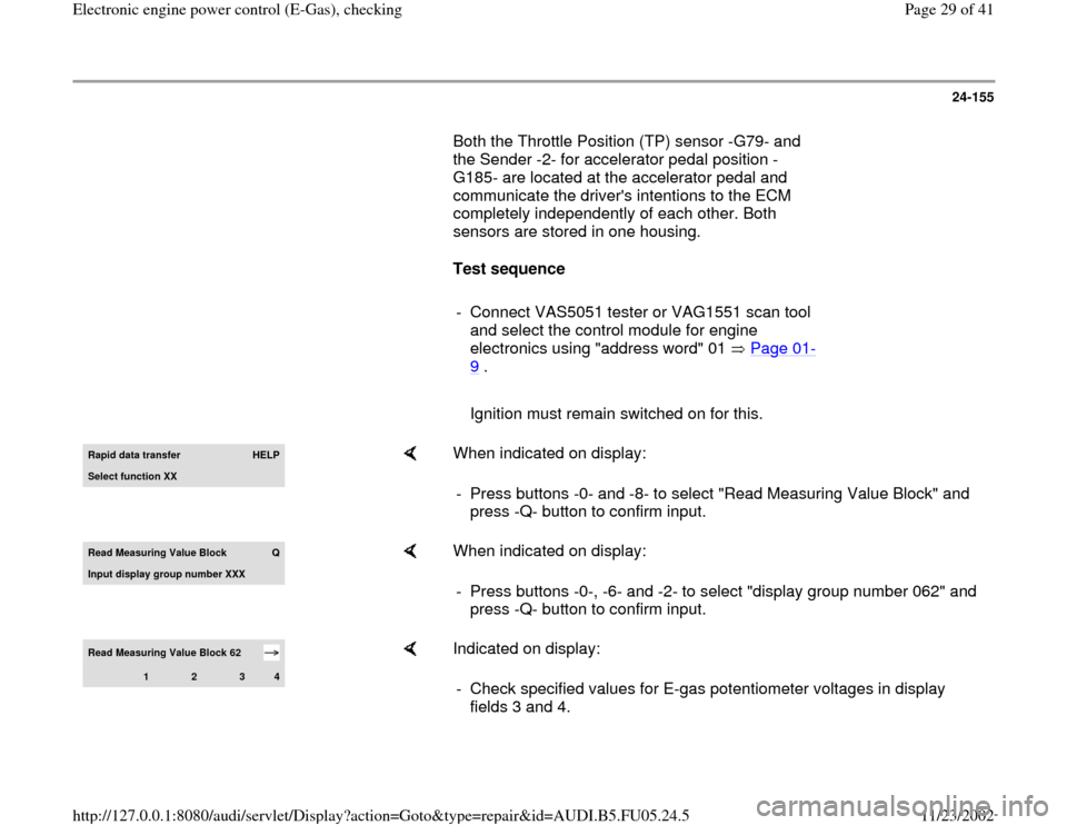
24-155
Both the Throttle Position (TP) sensor -G79- and
the Sender -2- for accelerator pedal position -
G185- are located at the accelerator pedal and
communicate the driver's intentions to the ECM
completely independently of each other. Both
sensors are stored in one housing.
Test sequence
- Connect VAS5051 tester or VAG1551 scan tool
and select the control module for engine
electronics using "address word" 01 Page 01
-
9 .
Ignition must remain switched on for this.Rapid data transfer
HELP
Select function XX
When indicated on display:
- Press buttons -0- and -8- to select "Read Measuring Value Block" and
press -Q- button to confirm input.
Read Measurin
g Value Block
Q
Input display group number XXX
When indicated on display:
- Press buttons -0-, -6- and -2- to select "display group number 062" and
press -Q- button to confirm input.
Read Measuring Value Block 62
1
2
3
4
Indicated on display:
- Check specified values for E-gas potentiometer voltages in display
fields 3 and 4.
Pa
ge 29 of 41 Electronic en
gine
power control
(E-Gas
), checkin
g
11/23/2002 htt
p://127.0.0.1:8080/audi/servlet/Dis
play?action=Goto&t
yp
e=re
pair&id=AUDI.B5.FU05.24.5
Page 30 of 41
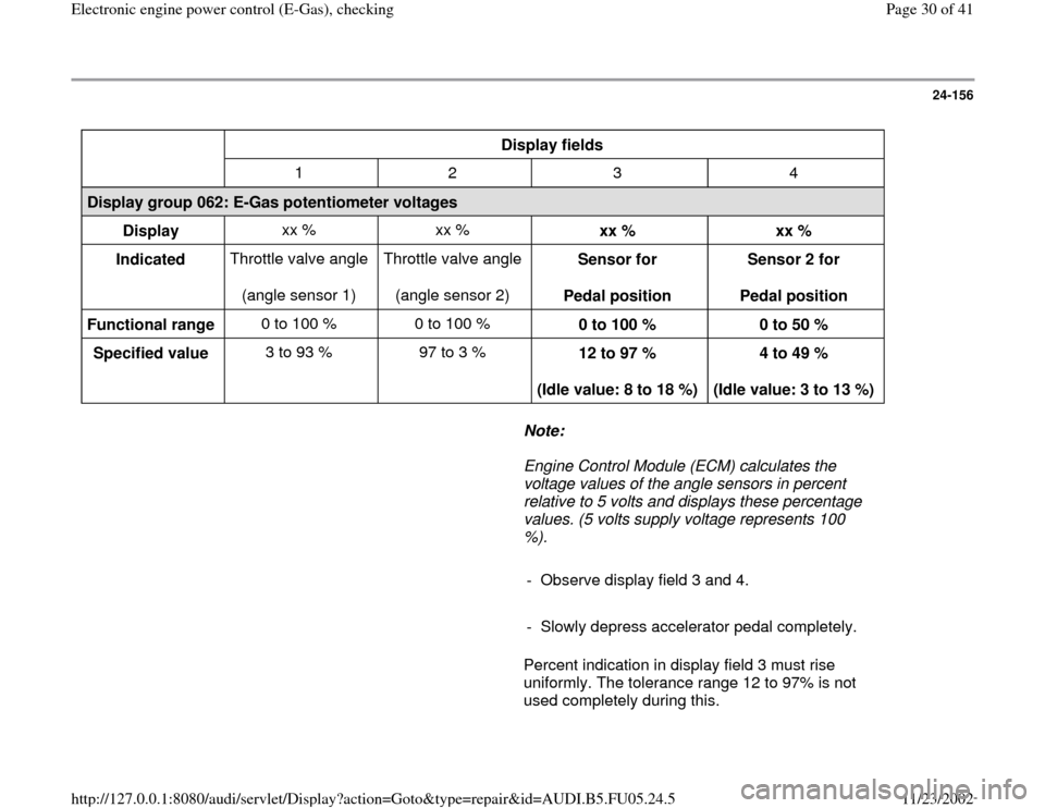
24-156
Display fields
1 2 3 4
Display group 062: E-Gas potentiometer voltages
Display xx % xx %
xx %
xx %
Indicated Throttle valve angle
(angle sensor 1) Throttle valve angle
(angle sensor 2) Sensor for
Pedal position Sensor 2 for
Pedal position
Functional range 0 to 100 % 0 to 100 %
0 to 100 %
0 to 50 %
Specified value 3 to 93 % 97 to 3 %
12 to 97 %
(Idle value: 8 to 18 %) 4 to 49 %
(Idle value: 3 to 13 %)
Note:
Engine Control Module (ECM) calculates the
voltage values of the angle sensors in percent
relative to 5 volts and displays these percentage
values. (5 volts supply voltage represents 100
%).
- Observe display field 3 and 4.
- Slowly depress accelerator pedal completely.
Percent indication in display field 3 must rise
uniformly. The tolerance range 12 to 97% is not
used completely during this.
Pa
ge 30 of 41 Electronic en
gine
power control
(E-Gas
), checkin
g
11/23/2002 htt
p://127.0.0.1:8080/audi/servlet/Dis
play?action=Goto&t
yp
e=re
pair&id=AUDI.B5.FU05.24.5