ESP AUDI A4 1995 B5 / 1.G Brakes Output DTM 03 Workshop Manual
[x] Cancel search | Manufacturer: AUDI, Model Year: 1995, Model line: A4, Model: AUDI A4 1995 B5 / 1.GPages: 66, PDF Size: 0.34 MB
Page 8 of 66
01-155
Output Diagnostic Test Mode (DTM)
-
Operate brake
Indicated on display:
-
Press button.
Output Diagnostic Test Mode (DTM)
-
Ifl: 0V
Ofl: 0V
fl wheel locked
Indicated on display:
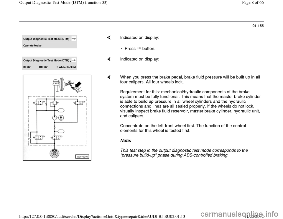
When you press the brake pedal, brake fluid pressure will be built up in all
four calipers. All four wheels lock.
Requirement for this: mechanical/hydraulic components of the brake
system must be fully functional. This means that the master brake cylinder
is able to build up pressure in all wheel cylinders and the hydraulic
connections and lines are all sealed properly. If the wheels do not lock,
visually inspect brake fluid reservoir, master brake cylinder, hydraulic unit,
and calipers.
Concentrate on the left-front wheel first. The function of the control
elements for this wheel is tested first.
Note:
This test step in the output diagnostic test mode corresponds to the
"pressure build-up" phase during ABS-controlled braking.
Pa
ge 8 of 66 Out
put Dia
gnostic Test Mode
(DTM
) (function 03
)
11/20/2002 htt
p://127.0.0.1:8080/audi/servlet/Dis
play?action=Goto&t
yp
e=re
pair&id=AUDI.B5.SU02.01.13
Page 9 of 66
01-156
-
Press button.Output Diagnostic Test Mode (DTM)
-
Ifl: B+
Ofl: 0V
fl wheel locked
Indicated on display:
Keep pressing brake pedal.
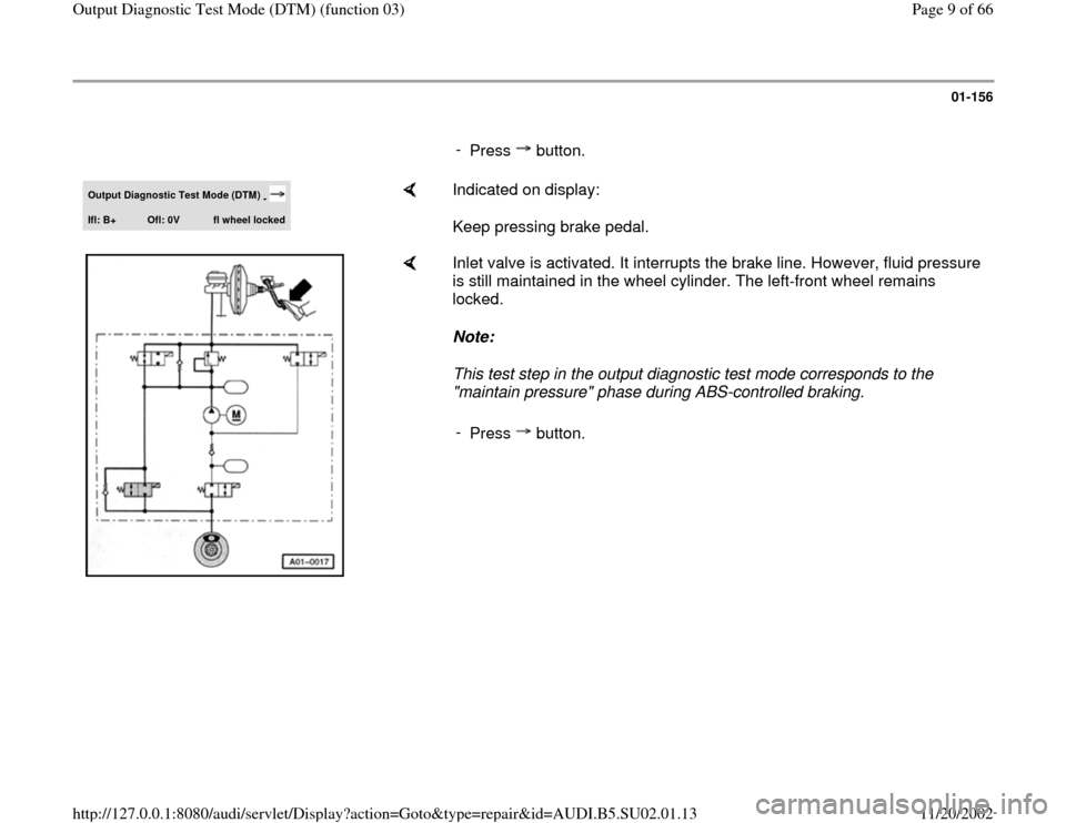
Inlet valve is activated. It interrupts the brake line. However, fluid pressure
is still maintained in the wheel cylinder. The left-front wheel remains
locked.
Note:
This test step in the output diagnostic test mode corresponds to the
"maintain pressure" phase during ABS-controlled braking.
-
Press button.
Pa
ge 9 of 66 Out
put Dia
gnostic Test Mode
(DTM
) (function 03
)
11/20/2002 htt
p://127.0.0.1:8080/audi/servlet/Dis
play?action=Goto&t
yp
e=re
pair&id=AUDI.B5.SU02.01.13
Page 10 of 66
01-157
Output Diagnostic Test Mode (DTM)
-
Ifl: B+
Ofl: B+
fl wheel free
Indicated on display:
Keep pressing brake pedal.
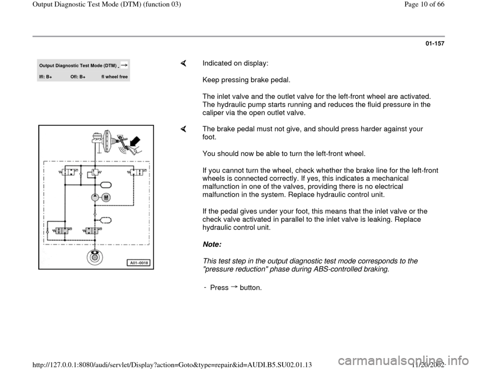
The inlet valve and the outlet valve for the left-front wheel are activated.
The hydraulic pump starts running and reduces the fluid pressure in the
caliper via the open outlet valve.
The brake pedal must not give, and should press harder against your
foot.
You should now be able to turn the left-front wheel.
If you cannot turn the wheel, check whether the brake line for the left-front
wheels is connected correctly. If yes, this indicates a mechanical
malfunction in one of the valves, providing there is no electrical
malfunction in the system. Replace hydraulic control unit.
If the pedal gives under your foot, this means that the inlet valve or the
check valve activated in parallel to the inlet valve is leaking. Replace
hydraulic control unit.
Note:
This test step in the output diagnostic test mode corresponds to the
"pressure reduction" phase during ABS-controlled braking.
-
Press button.
Pa
ge 10 of 66 Out
put Dia
gnostic Test Mode
(DTM
) (function 03
)
11/20/2002 htt
p://127.0.0.1:8080/audi/servlet/Dis
play?action=Goto&t
yp
e=re
pair&id=AUDI.B5.SU02.01.13
Page 28 of 66
01-173
Notes:
For test table:
The socket designations of the VAG1598 test box are identical to the terminal designations of the ABS control module
(w/EDL) -J104- in the wiring diagram. Incorrect test procedures can cause damage to the system. Do not bridge any
terminals other than those listed in the table.
Electrical Wiring Diagrams, Troubleshooting & Component Locations Specified values refer to readings on the VAG1526 and are not necessarily applicable for other test units.
If the measured values do not match specifications, carry out the corrective actions listed on the right side of the table.
Electrical Wiring Diagrams, Troubleshooting & Component Locations If values are obtained, also check wiring for intermittent loose terminals and short circuit to B+ and Ground (GND). This
applies especially to sporadic malfunctions.
Use only the VAG1594 connector test kit for checking continuity (bridges).
If the measured values only differ slightly from the specifications, clean the sockets and harness connectors of the testers
and adapter leads (using contact spray G 000 700 04) and repeat the test. Before replacing actual components, check
wiring and connections once more. This is especially important if the specification for a resistance test is under 10 .
Pa
ge 28 of 66 Out
put Dia
gnostic Test Mode
(DTM
) (function 03
)
11/20/2002 htt
p://127.0.0.1:8080/audi/servlet/Dis
play?action=Goto&t
yp
e=re
pair&id=AUDI.B5.SU02.01.13
Page 43 of 66
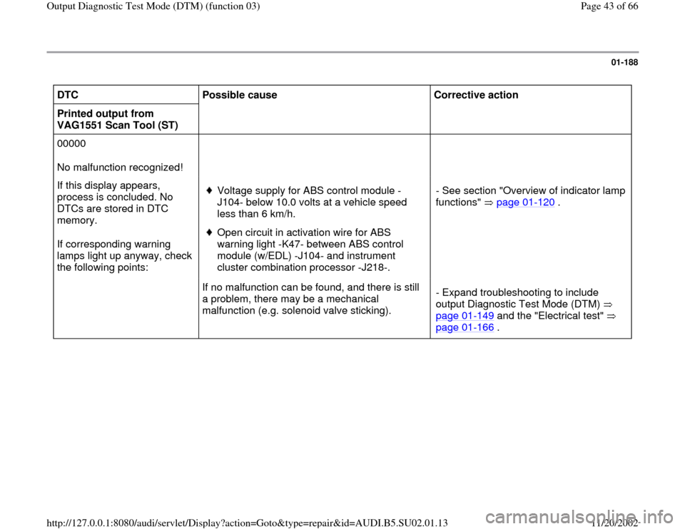
01-188
DTC
Possible cause
Corrective action
Printed output from
VAG1551 Scan Tool (ST)
00000
No malfunction recognized!
If this display appears,
process is concluded. No
DTCs are stored in DTC
memory.
If corresponding warning
lamps light up anyway, check
the following points:
Voltage supply for ABS control module -
J104- below 10.0 volts at a vehicle speed
less than 6 km/h. Open circuit in activation wire for ABS
warning light -K47- between ABS control
module (w/EDL) -J104- and instrument
cluster combination processor -J218-. - See section "Overview of indicator lamp
functions" page 01
-120
.
If no malfunction can be found, and there is still
a problem, there may be a mechanical
malfunction (e.g. solenoid valve sticking). - Expand troubleshooting to include
output Diagnostic Test Mode (DTM)
page 01
-149
and the "Electrical test"
page 01
-166
.
Pa
ge 43 of 66 Out
put Dia
gnostic Test Mode
(DTM
) (function 03
)
11/20/2002 htt
p://127.0.0.1:8080/audi/servlet/Dis
play?action=Goto&t
yp
e=re
pair&id=AUDI.B5.SU02.01.13
Page 63 of 66
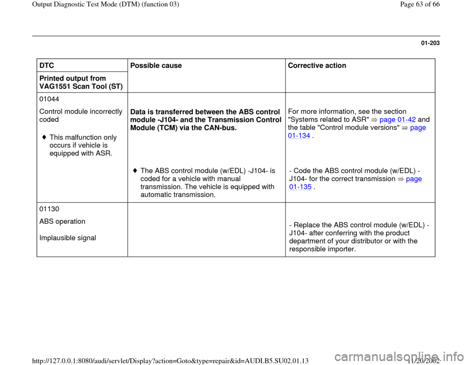
01-203
DTC
Possible cause
Corrective action
Printed output from
VAG1551 Scan Tool (ST)
01044
Control module incorrectly
coded
This malfunction only
occurs if vehicle is
equipped with ASR. Data is transferred between the ABS control
module -J104- and the Transmission Control
Module (TCM) via the CAN-bus. For more information, see the section
"Systems related to ASR" page 01
-42
and
the table "Control module versions" page
01
-134
.
The ABS control module (w/EDL) -J104- is
coded for a vehicle with manual
transmission. The vehicle is equipped with
automatic transmission. - Code the ABS control module (w/EDL) -
J104- for the correct transmission page
01
-135
.
01130
ABS operation
Implausible signal
- Replace the ABS control module (w/EDL) -
J104- after conferring with the product
department of your distributor or with the
responsible importer.
Pa
ge 63 of 66 Out
put Dia
gnostic Test Mode
(DTM
) (function 03
)
11/20/2002 htt
p://127.0.0.1:8080/audi/servlet/Dis
play?action=Goto&t
yp
e=re
pair&id=AUDI.B5.SU02.01.13