bulb AUDI A4 1995 B5 / 1.G Brakes Output DTM 03 Workshop Manual
[x] Cancel search | Manufacturer: AUDI, Model Year: 1995, Model line: A4, Model: AUDI A4 1995 B5 / 1.GPages: 66, PDF Size: 0.34 MB
Page 35 of 66

01-180
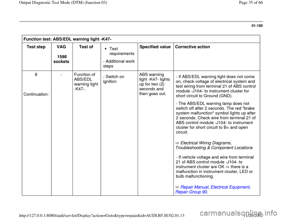
Function test: ABS/EDL warning light -K47-
Test step
VAG
1598
sockets Test of
Test
requirements
- Additional work
steps Specified value
Corrective action
8
Continuation: - Function of
ABS/EDL
warning light
-K47-. - Switch on
ignition ABS warning
light -K47- lights
up for two (2)
seconds and
then goes out.
Electrical Wiring Diagrams,
Troubleshooting & Component Locations - If ABS/EDL warning light does not come
on, check voltage of electrical system and
test wiring from terminal 21 of ABS control
module -J104- to instrument cluster for
short circuit to Ground (GND).
- The ABS/EDL warning lamp does not
switch off after 2 seconds. The red "brake
system malfunction" symbol lights up after
2 seconds. Check wire from terminal 21 of
ABS control module -J104- to instrument
cluster for short circuit to B+ and open
circuit.
Repair Manual, Electrical Equipment,
Repair Group 90.
- If vehicle voltage and wire from terminal
21 of ABS control module -J104- to
instrument cluster are OK there is a
malfunction in instrument cluster, LED or
bulb malfunctioning.
Pa
ge 35 of 66 Out
put Dia
gnostic Test Mode
(DTM
) (function 03
)
11/20/2002 htt
p://127.0.0.1:8080/audi/servlet/Dis
play?action=Goto&t
yp
e=re
pair&id=AUDI.B5.SU02.01.13
Page 39 of 66

01-184
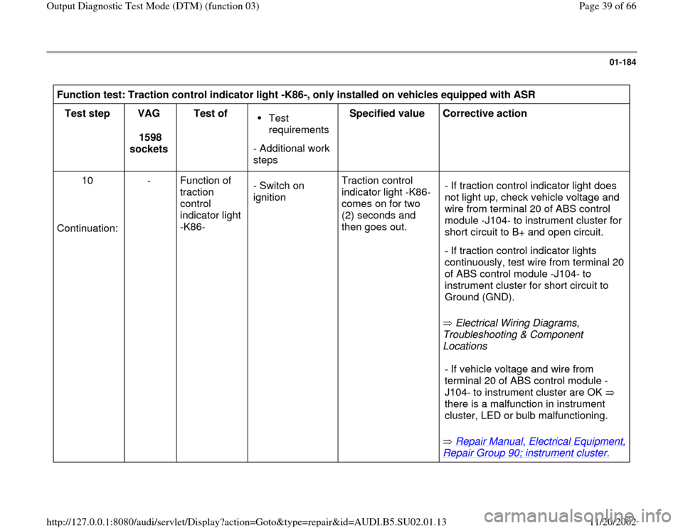
Function test: Traction control indicator light -K86-, only installed on vehicles equipped with ASR
Test step
VAG
1598
sockets Test of
Test
requirements
- Additional work
steps Specified value
Corrective action
10
Continuation: - Function of
traction
control
indicator light
-K86- - Switch on
ignition Traction control
indicator light -K86-
comes on for two
(2) seconds and
then goes out.
Electrical Wiring Diagrams,
Troubleshooting & Component
Locations - If traction control indicator light does
not light up, check vehicle voltage and
wire from terminal 20 of ABS control
module -J104- to instrument cluster for
short circuit to B+ and open circuit.
- If traction control indicator lights
continuously, test wire from terminal 20
of ABS control module -J104- to
instrument cluster for short circuit to
Ground (GND).
Repair Manual, Electrical Equipment,
Repair Group 90; instrument cluster.
- If vehicle voltage and wire from
terminal 20 of ABS control module -
J104- to instrument cluster are OK
there is a malfunction in instrument
cluster, LED or bulb malfunctioning.
Pa
ge 39 of 66 Out
put Dia
gnostic Test Mode
(DTM
) (function 03
)
11/20/2002 htt
p://127.0.0.1:8080/audi/servlet/Dis
play?action=Goto&t
yp
e=re
pair&id=AUDI.B5.SU02.01.13
Page 53 of 66

01-194
DTC
Possible cause
Corrective action
Printed output from
VAG1551 Scan Tool (ST)
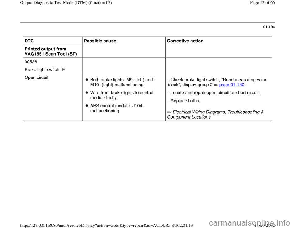
00526
Brake light switch -F-
Open circuit
Both brake lights -M9- (left) and -
M10- (right) malfunctioning.
Wire from brake lights to control
module faulty.
ABS control module -J104-
malfunctioning
Electrical Wiring Diagrams, Troubleshooting &
Component Locations - Check brake light switch, "Read measuring value
block", display group 2 page 01
-140
.
- Locate and repair open circuit or short circuit.
- Replace bulbs.
Pa
ge 53 of 66 Out
put Dia
gnostic Test Mode
(DTM
) (function 03
)
11/20/2002 htt
p://127.0.0.1:8080/audi/servlet/Dis
play?action=Goto&t
yp
e=re
pair&id=AUDI.B5.SU02.01.13