engine AUDI A4 1996 B5 / 1.G 01V Transmission Remove And Install User Guide
[x] Cancel search | Manufacturer: AUDI, Model Year: 1996, Model line: A4, Model: AUDI A4 1996 B5 / 1.GPages: 64, PDF Size: 1.44 MB
Page 13 of 64
37-83
Continuation for all vehicles
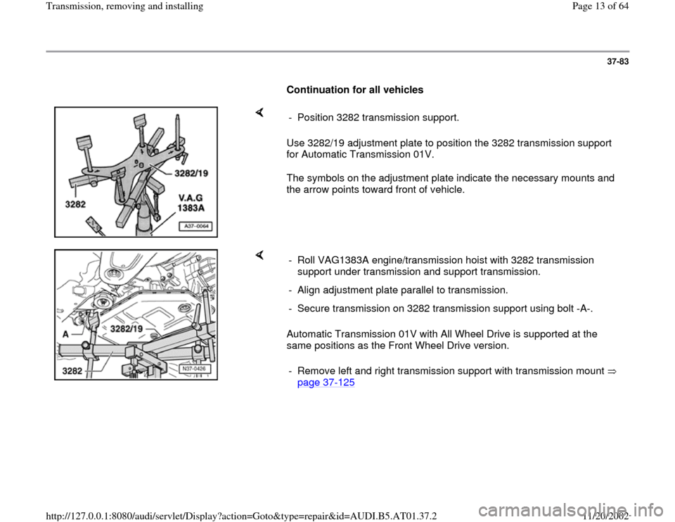
Use 3282/19 adjustment plate to position the 3282 transmission support
for Automatic Transmission 01V.
The symbols on the adjustment plate indicate the necessary mounts and
the arrow points toward front of vehicle. - Position 3282 transmission support.
Automatic Transmission 01V with All Wheel Drive is supported at the
same positions as the Front Wheel Drive version. - Roll VAG1383A engine/transmission hoist with 3282 transmission
support under transmission and support transmission.
- Align adjustment plate parallel to transmission.
- Secure transmission on 3282 transmission support using bolt -A-.
- Remove left and right transmission support with transmission mount
page 37
-125
Pa
ge 13 of 64 Transmission, removin
g and installin
g
11/20/2002 htt
p://127.0.0.1:8080/audi/servlet/Dis
play?action=Goto&t
yp
e=re
pair&id=AUDI.B5.AT01.37.2
Page 15 of 64
37-85
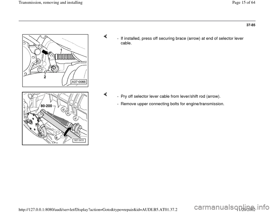
- If installed, press off securing brace (arrow) at end of selector lever
cable.
- Pry off selector lever cable from lever/shift rod (arrow).
- Remove upper connecting bolts for engine/transmission.
Pa
ge 15 of 64 Transmission, removin
g and installin
g
11/20/2002 htt
p://127.0.0.1:8080/audi/servlet/Dis
play?action=Goto&t
yp
e=re
pair&id=AUDI.B5.AT01.37.2
Page 16 of 64
37-86
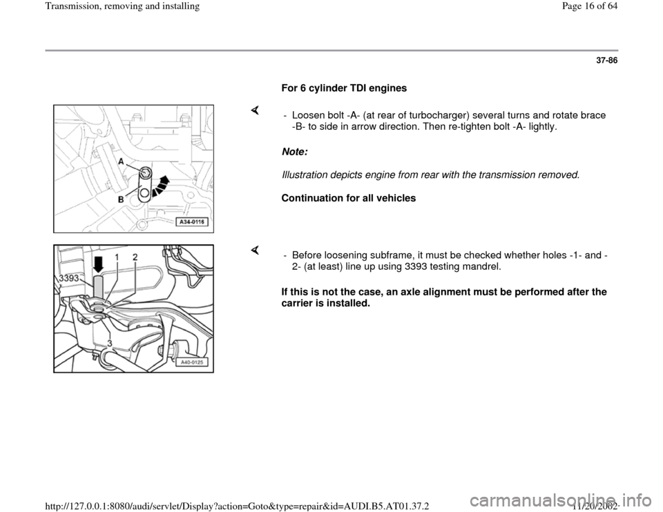
For 6 cylinder TDI engines
Note:
Illustration depicts engine from rear with the transmission removed.
Continuation for all vehicles - Loosen bolt -A- (at rear of turbocharger) several turns and rotate brace
-B- to side in arrow direction. Then re-tighten bolt -A- lightly.
If this is not the case, an axle alignment must be performed after the
carrier is installed. - Before loosening subframe, it must be checked whether holes -1- and -
2- (at least) line up using 3393 testing mandrel.
Pa
ge 16 of 64 Transmission, removin
g and installin
g
11/20/2002 htt
p://127.0.0.1:8080/audi/servlet/Dis
play?action=Goto&t
yp
e=re
pair&id=AUDI.B5.AT01.37.2
Page 17 of 64
37-87
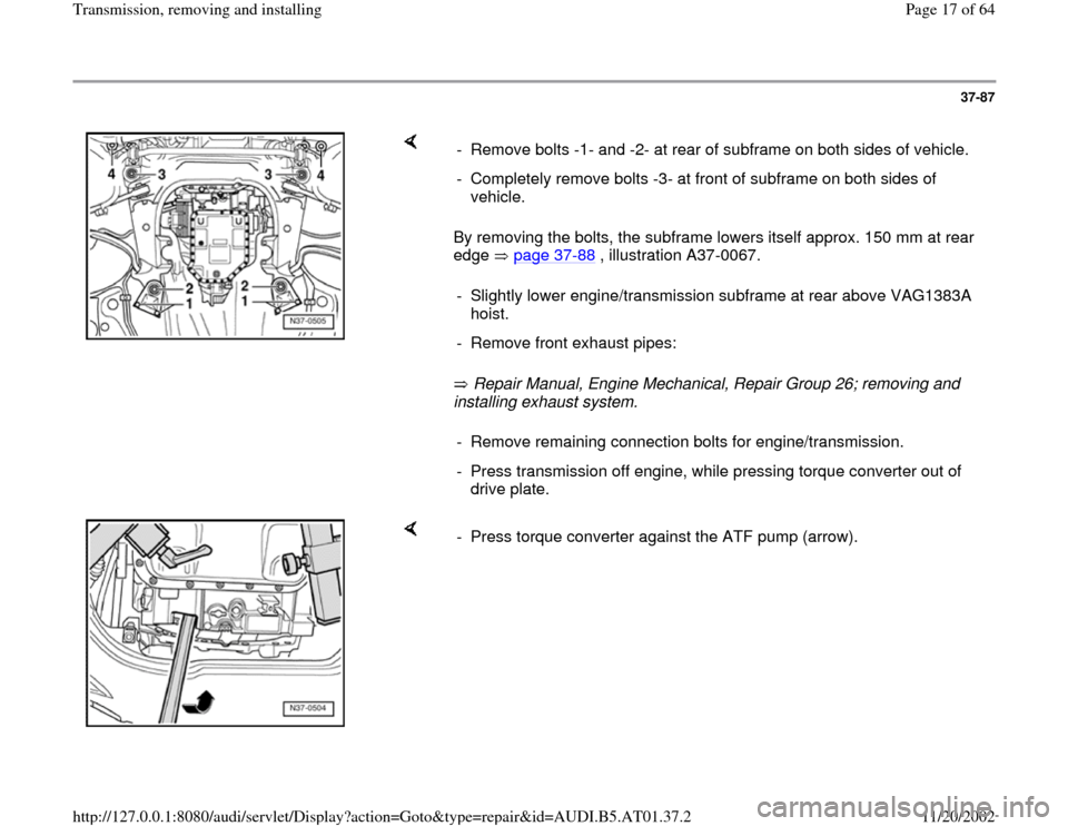
By removing the bolts, the subframe lowers itself approx. 150 mm at rear
edge page 37
-88
, illustration A37-0067.
Repair Manual, Engine Mechanical, Repair Group 26; removing and
installing exhaust system. - Remove bolts -1- and -2- at rear of subframe on both sides of vehicle.
- Completely remove bolts -3- at front of subframe on both sides of
vehicle.
- Slightly lower engine/transmission subframe at rear above VAG1383A
hoist.
- Remove front exhaust pipes:- Remove remaining connection bolts for engine/transmission.
- Press transmission off engine, while pressing torque converter out of
drive plate.
- Press torque converter against the ATF pump (arrow).
Pa
ge 17 of 64 Transmission, removin
g and installin
g
11/20/2002 htt
p://127.0.0.1:8080/audi/servlet/Dis
play?action=Goto&t
yp
e=re
pair&id=AUDI.B5.AT01.37.2
Page 19 of 64
37-89
Installing
Installation is reverse of removal, noting the
following:
Before installing:
All-wheel-drive vehicles
- Clean threads in driveshaft flange!
Continuation for all vehicles
- Clean ATF lines page 37
-158
.
- Insert torque converter into transmission page
32
-8 .
WARNING!
Check installation dimension of torque
converter before installing transmission
page 32
-8
- Make sure bushings are correctly seated.
Note:
If the bushings get stuck in the transmission
housing, they must be removed and new
bushings must be installed on the engine.
Pa
ge 19 of 64 Transmission, removin
g and installin
g
11/20/2002 htt
p://127.0.0.1:8080/audi/servlet/Dis
play?action=Goto&t
yp
e=re
pair&id=AUDI.B5.AT01.37.2
Page 20 of 64
37-90
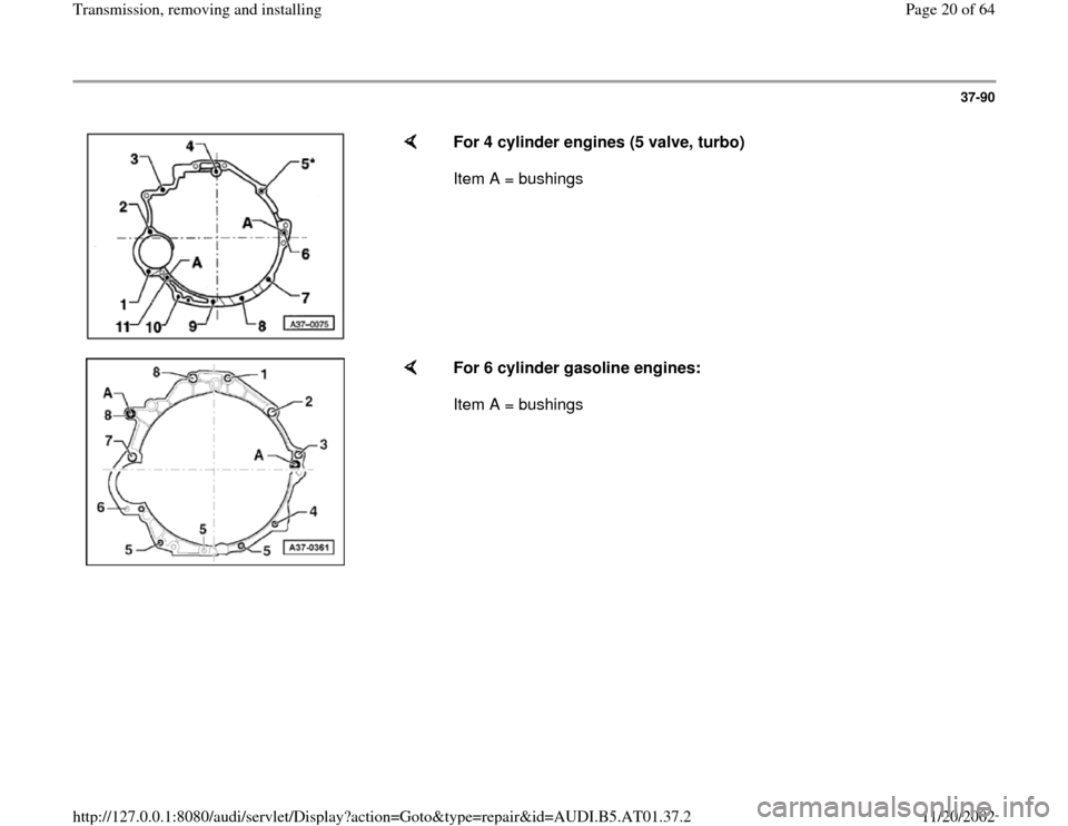
For 4 cylinder engines (5 valve, turbo)
Item A = bushings
For 6 cylinder gasoline engines:
Item A = bushings
Pa
ge 20 of 64 Transmission, removin
g and installin
g
11/20/2002 htt
p://127.0.0.1:8080/audi/servlet/Dis
play?action=Goto&t
yp
e=re
pair&id=AUDI.B5.AT01.37.2
Page 21 of 64
37-91
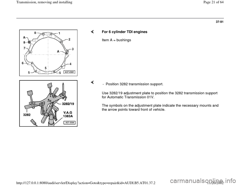
For 6 cylinder TDI engines
Item A = bushings
Use 3282/19 adjustment plate to position the 3282 transmission support
for Automatic Transmission 01V.
The symbols on the adjustment plate indicate the necessary mounts and
the arrow points toward front of vehicle. - Position 3282 transmission support.
Pa
ge 21 of 64 Transmission, removin
g and installin
g
11/20/2002 htt
p://127.0.0.1:8080/audi/servlet/Dis
play?action=Goto&t
yp
e=re
pair&id=AUDI.B5.AT01.37.2
Page 22 of 64
37-92
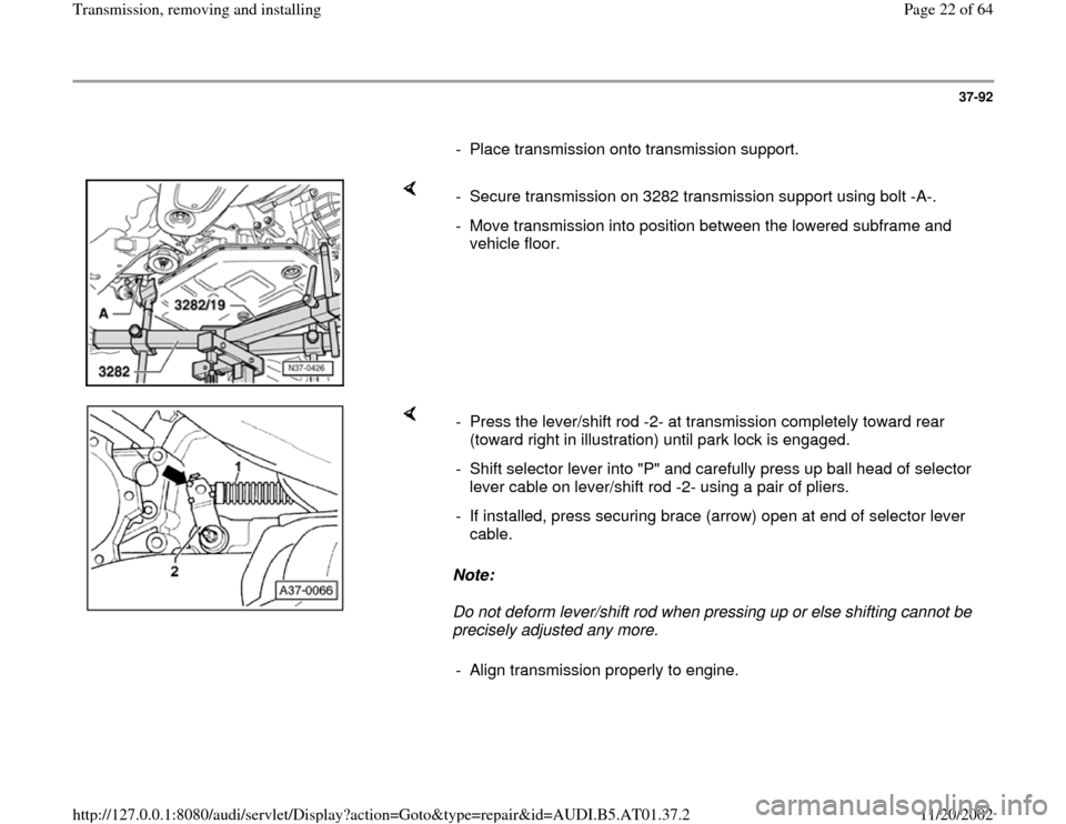
- Place transmission onto transmission support.
- Secure transmission on 3282 transmission support using bolt -A-.
- Move transmission into position between the lowered subframe and
vehicle floor.
Note:
Do not deform lever/shift rod when pressing up or else shifting cannot be
precisely adjusted any more. - Press the lever/shift rod -2- at transmission completely toward rear
(toward right in illustration) until park lock is engaged.
- Shift selector lever into "P" and carefully press up ball head of selector
lever cable on lever/shift rod -2- using a pair of pliers.
- If installed, press securing brace (arrow) open at end of selector lever
cable.
- Align transmission properly to engine.
Pa
ge 22 of 64 Transmission, removin
g and installin
g
11/20/2002 htt
p://127.0.0.1:8080/audi/servlet/Dis
play?action=Goto&t
yp
e=re
pair&id=AUDI.B5.AT01.37.2
Page 23 of 64
37-93
Note:
If installed, place intermediate plate onto
bushings.
Make sure that wires do not get pinched as
transmission is docked at engine.
Check whether the torque converter is still
properly installed and has not slid out of the
converter housing toward the font:
- It must be possible to easily turn torque
converter by hand without much force.
WARNING!
In case of an incorrectly inserted torque
converter, the coupling plate of the torque
converter or the ATF-pump will be destroyed,
if the transmission is flanged to the engine.
- If the torque converter is difficult to move, check
installation dimension once again page 32
-8 .
Pa
ge 23 of 64 Transmission, removin
g and installin
g
11/20/2002 htt
p://127.0.0.1:8080/audi/servlet/Dis
play?action=Goto&t
yp
e=re
pair&id=AUDI.B5.AT01.37.2
Page 24 of 64
37-94
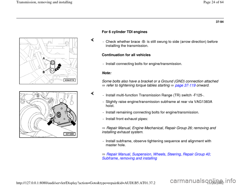
For 6 cylinder TDI engines
Continuation for all vehicles
Note:
Some bolts also have a bracket or a Ground (GND) connection attached
refer to tightening torque tables starting page 37
-119
onward. - Check whether brace -B- is still swung to side (arrow direction) before
installing the transmission.
- Install connecting bolts for engine/transmission.
Repair Manual, Engine Mechanical, Repair Group 26; removing and
installing exhaust system.
Repair Manual, Suspension, Wheels, Steering, Repair Group 40;
Subframe, removing and installing
- Install multi-function Transmission Range (TR) switch -F125-.
- Slightly raise engine/transmission subframe at rear via VAG1383A
hoist.
- Install remaining connecting bolts for engine/transmission.
- Install front exhaust pipes:
- Install subframe, observe tightening sequence and alignment with
master hole.
Pa
ge 24 of 64 Transmission, removin
g and installin
g
11/20/2002 htt
p://127.0.0.1:8080/audi/servlet/Dis
play?action=Goto&t
yp
e=re
pair&id=AUDI.B5.AT01.37.2