battery AUDI A4 1996 B5 / 1.G AEB Engine Motronic MFI And Ignition System
[x] Cancel search | Manufacturer: AUDI, Model Year: 1996, Model line: A4, Model: AUDI A4 1996 B5 / 1.GPages: 135, PDF Size: 0.71 MB
Page 5 of 135
24-5
Safety precautions
WARNING!
Fire hazard! Do not smoke, work near heaters
or open flame, or have anything nearby that
could ignite fuel. The fuel system is under
pressure. Before opening, cover connections
with a rag, and open carefully to release
pressure. Be alert when working on or near
the engine and ignition wires. High secondary
ignition voltage can cause serious personal
injury and damage vehicle components.
DO NOT touch or disconnect ignition system
wires when the engine is running or being
cranked at starting RPM.
DO NOT operate starter if fuel injectors are
removed.
Be sure the ignition is switched OFF, when:
Disconnecting or connecting the battery,
ignition wires, or test equipment leads
Disconnecting fuel injection system wiring
Washing the engine or engine
compartment.
Pa
ge 5 of 135 Motronic Multi
port Fuel In
jection
(MFI
) and i
gnition s
ystem
11/19/2002 htt
p://127.0.0.1:8080/audi/servlet/Dis
play?action=Goto&t
yp
e=re
pair&id=AUDI.B5.FU02.24.1
Page 7 of 135
24-6
CAUTION!
BEFORE disconnecting the battery:
Stop the engine.
Be sure the ignition is switched OFF (also
applies when connecting the battery). Failure
to do so may damage the Engine Control
Module (ECM).
Be sure of the proper radio code (for vehicles
equipped with coded anti-theft radio).
Be sure the battery negative (-) cable is
disconnected, when:
Working on the electrical system
Resistance (spot) welding or electric arc
welding anywhere on the vehicle.
When connecting and disconnecting
electrical test equipment (LED voltage tester,
multimeter, etc.):
Be sure the ignition is switched OFF.
Use correct adapters from the VW 1594
Pa
ge 7 of 135 Motronic Multi
port Fuel In
jection
(MFI
) and i
gnition s
ystem
11/19/2002 htt
p://127.0.0.1:8080/audi/servlet/Dis
play?action=Goto&t
yp
e=re
pair&id=AUDI.B5.FU02.24.1
Page 12 of 135
24-9
Fuel injection system, servicing
Servicing ignition system:
Repair Group 28
Notes:
Fuel hoses in the engine compartment must be
secured with spring-type clamps. Screw-type
clamps or equivalent must not be used.
The Engine Control Module (ECM) has On
Board Diagnostic (OBD) capability, and is
equipped with Diagnostic Trouble Code (DTC)
memory. Before repairing or adjusting any
components or systems, first check DTC
memory. Also check all vacuum connections for
leaks ("false air").
For proper operation of electrical and electronic
components, a Battery Positive Voltage (B+)
supply of at least 11.5 volts is required.
Do not use any gasket sealers or other
automotive chemical compounds that contain
silicone. Traces of silicone drawn into the
engine pass unburned into the exhaust and can
damage the oxygen sensors.
Pa
ge 12 of 135 Motronic Multi
port Fuel In
jection
(MFI
) and i
gnition s
ystem
11/19/2002 htt
p://127.0.0.1:8080/audi/servlet/Dis
play?action=Goto&t
yp
e=re
pair&id=AUDI.B5.FU02.24.1
Page 46 of 135
24-33
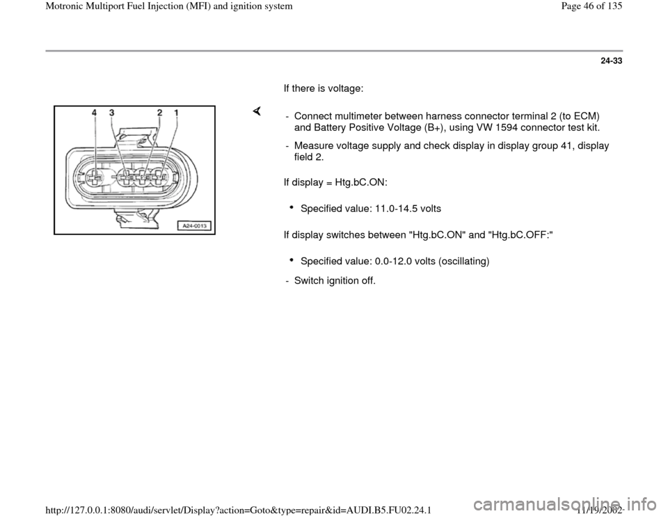
If there is voltage:
If display = Htg.bC.ON:
If display switches between "Htg.bC.ON" and "Htg.bC.OFF:" - Connect multimeter between harness connector terminal 2 (to ECM)
and Battery Positive Voltage (B+), using VW 1594 connector test kit.
- Measure voltage supply and check display in display group 41, display
field 2.
Specified value: 11.0-14.5 volts Specified value: 0.0-12.0 volts (oscillating)
- Switch ignition off.
Pa
ge 46 of 135 Motronic Multi
port Fuel In
jection
(MFI
) and i
gnition s
ystem
11/19/2002 htt
p://127.0.0.1:8080/audi/servlet/Dis
play?action=Goto&t
yp
e=re
pair&id=AUDI.B5.FU02.24.1
Page 65 of 135
24-49
If there is voltage:
If display = Htg.aC.ON:
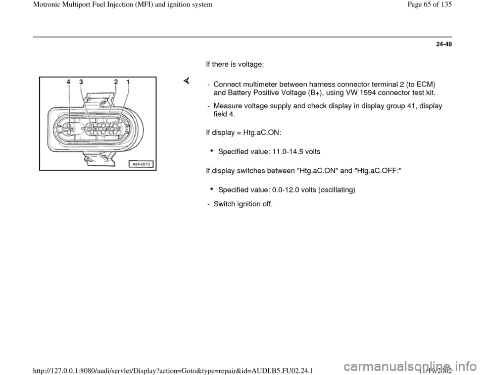
If display switches between "Htg.aC.ON" and "Htg.aC.OFF:" - Connect multimeter between harness connector terminal 2 (to ECM)
and Battery Positive Voltage (B+), using VW 1594 connector test kit.
- Measure voltage supply and check display in display group 41, display
field 4.
Specified value: 11.0-14.5 volts Specified value: 0.0-12.0 volts (oscillating)
- Switch ignition off.
Pa
ge 65 of 135 Motronic Multi
port Fuel In
jection
(MFI
) and i
gnition s
ystem
11/19/2002 htt
p://127.0.0.1:8080/audi/servlet/Dis
play?action=Goto&t
yp
e=re
pair&id=AUDI.B5.FU02.24.1
Page 82 of 135
24-62
- Check wiring for short circuits between terminals
of 4-pin connector, and between connector and
ECM/test box.
Connector terminal 4 to ECM/test box
socket 12
Specified value:
- Switch multimeter to 20 VDC measuring
range.
- Check wiring at 4-pin connector for short circuit
to B+ (battery positive voltage), according to
applicable wiring diagram.
Connector terminal 2 to vehicle Ground
Connector terminal 4 to vehicle Ground
Specified value: 0 volts
If wiring is OK:
- Replace Mass Air Flow sensor (MAF) -G70-.
-
Check readiness code Page 01
-59
. If
Pa
ge 82 of 135 Motronic Multi
port Fuel In
jection
(MFI
) and i
gnition s
ystem
11/19/2002 htt
p://127.0.0.1:8080/audi/servlet/Dis
play?action=Goto&t
yp
e=re
pair&id=AUDI.B5.FU02.24.1
Page 90 of 135
24-67
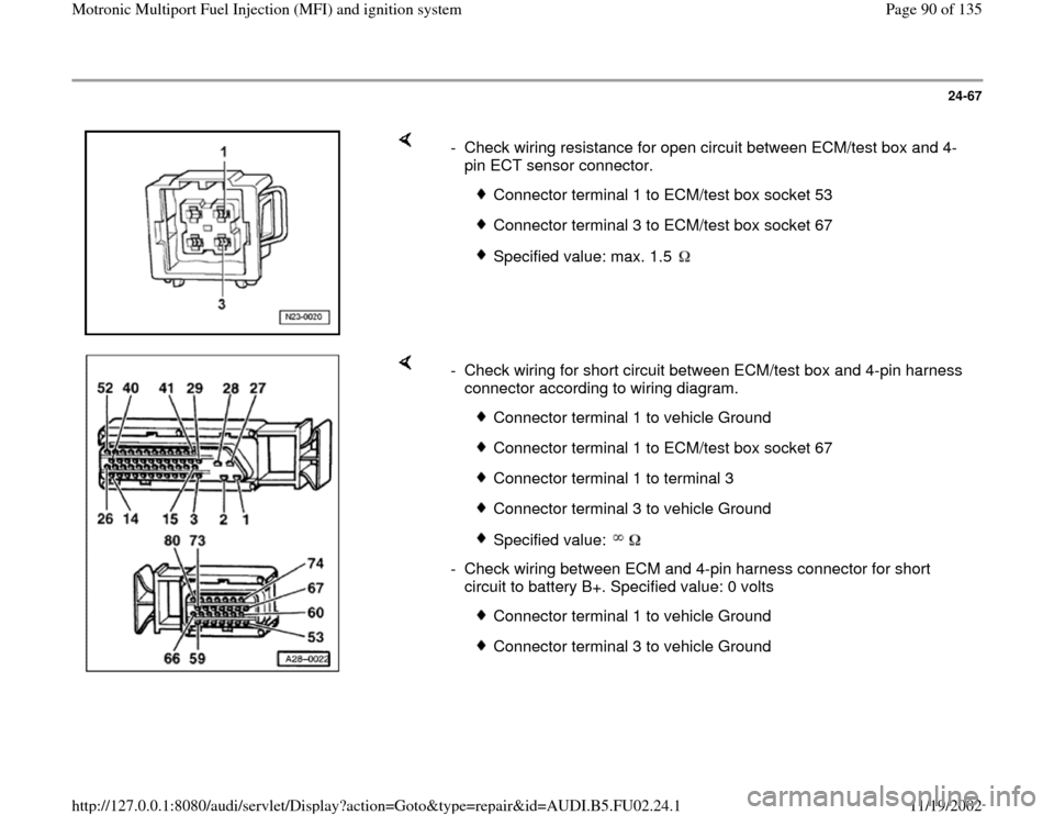
- Check wiring resistance for open circuit between ECM/test box and 4-
pin ECT sensor connector.
Connector terminal 1 to ECM/test box socket 53
Connector terminal 3 to ECM/test box socket 67
Specified value: max. 1.5
- Check wiring for short circuit between ECM/test box and 4-pin harness
connector according to wiring diagram.
Connector terminal 1 to vehicle Ground
Connector terminal 1 to ECM/test box socket 67
Connector terminal 1 to terminal 3
Connector terminal 3 to vehicle Ground
Specified value:
- Check wiring between ECM and 4-pin harness connector for short
circuit to battery B+. Specified value: 0 volts
Connector terminal 1 to vehicle Ground
Connector terminal 3 to vehicle Ground
Pa
ge 90 of 135 Motronic Multi
port Fuel In
jection
(MFI
) and i
gnition s
ystem
11/19/2002 htt
p://127.0.0.1:8080/audi/servlet/Dis
play?action=Goto&t
yp
e=re
pair&id=AUDI.B5.FU02.24.1
Page 94 of 135
24-71
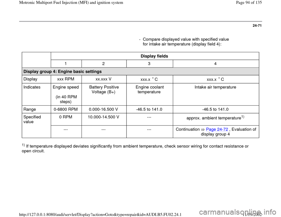
- Compare displayed value with specified value
for intake air temperature (display field 4):
Display fields
1 2 3 4
Display group 4: Engine basic settings
Display xxx RPM xx.xxx V
xxx.x C
xxx.x C
Indicates Engine speed
(in 40 RPM
steps) Battery Positive
Voltage (B+) Engine coolant
temperature Intake air temperature
Range 0-6800 RPM 0.000-16.500 V -46.5 to 141.0 -46.5 to 141.0
Specified
value 0 RPM 10.000-14.500 V ---
approx. ambient temperature
1)
--- --- --- Continuation Page 24
-72
, Evaluation of
display group 4
1) If temperature displayed deviates significantly from ambient temperature, check sensor wiring for contact resistance or
open circuit.
Pa
ge 94 of 135 Motronic Multi
port Fuel In
jection
(MFI
) and i
gnition s
ystem
11/19/2002 htt
p://127.0.0.1:8080/audi/servlet/Dis
play?action=Goto&t
yp
e=re
pair&id=AUDI.B5.FU02.24.1
Page 97 of 135
24-73
- Check wiring for short circuit between ECM/test
box and 2-pin harness connector according to
wiring diagram.
Connector terminal 1 to vehicle Ground
Connector terminal 1 to ECM/test box
socket 67
Connector terminal 1 to terminal 2
Connector terminal 2 to vehicle Ground
Specified value:
- Check wiring between ECM and 2-pin harness
connector for short circuit to battery B+.
Connector terminal 1 to vehicle Ground
Connector terminal 2 to vehicle Ground
Specified value: 0 volts
- Check resistance across terminals of IAT sensor -G42-.
Pa
ge 97 of 135 Motronic Multi
port Fuel In
jection
(MFI
) and i
gnition s
ystem
11/19/2002 htt
p://127.0.0.1:8080/audi/servlet/Dis
play?action=Goto&t
yp
e=re
pair&id=AUDI.B5.FU02.24.1
Page 105 of 135
24-78
- Check battery positive voltage (B+) in display
field 2.
Display fields
1 2 3 4
Display group 4: Basic engine setting
Display xxx RPM xx.xxx V
xxx.x C
xxx.x 5C
Indicates Engine speed
(in 40 RPM
steps) Battery Positive Voltage (B+) Engine coolant
temperature Intake air
temperature
Range 0-6800 RPM 0.000-16.500 V -46.5 to 141.0 -46.5 to 141.0
Specified
value 0 RPM 10.000-14.500 V --- ---
--- If not as specified Page 24
-79
, Evaluation
of display group 4
--- ---
If displayed value is OK (as specified):
-
Press button to advance program
sequence.
- Press buttons -0- and -6- to select "End Output"
function 06, and press -Q- button to confirm
input.
Pa
ge 105 of 135 Motronic Multi
port Fuel In
jection
(MFI
) and i
gnition s
ystem
11/19/2002 htt
p://127.0.0.1:8080/audi/servlet/Dis
play?action=Goto&t
yp
e=re
pair&id=AUDI.B5.FU02.24.1