relay AUDI A4 1996 B5 / 1.G AEB Engine Motronic MFI And Ignition System
[x] Cancel search | Manufacturer: AUDI, Model Year: 1996, Model line: A4, Model: AUDI A4 1996 B5 / 1.GPages: 135, PDF Size: 0.71 MB
Page 1 of 135
24-1
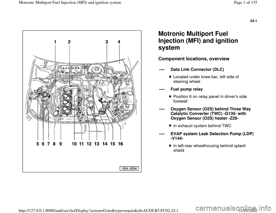
Motronic Multiport Fuel
Injection (MFI) and ignition
system Component locations, overview
----
Data Link Connector (DLC)
Located under knee bar, left side of
steering wheel
----
Fuel pump relayPosition 6 on relay panel in driver's side
footwell
----
Oxygen Sensor (O2S) behind Three Way
Catalytic Converter (TWC) -G130- with
Oxygen Sensor (O2S) heater -Z29- In exhaust system behind TWC
----
EVAP system Leak Detection Pump (LDP)
-V144- In left-rear wheelhousing behind splash
shield
Pa
ge 1 of 135 Motronic Multi
port Fuel In
jection
(MFI
) and i
gnition s
ystem
11/19/2002 htt
p://127.0.0.1:8080/audi/servlet/Dis
play?action=Goto&t
yp
e=re
pair&id=AUDI.B5.FU02.24.1
Page 45 of 135
24-32
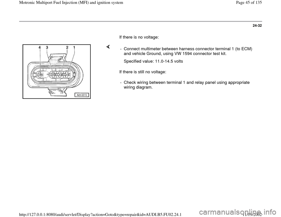
If there is no voltage:
If there is still no voltage: - Connect multimeter between harness connector terminal 1 (to ECM)
and vehicle Ground, using VW 1594 connector test kit.
Specified value: 11.0-14.5 volts
- Check wiring between terminal 1 and relay panel using appropriate
wiring diagram.
Pa
ge 45 of 135 Motronic Multi
port Fuel In
jection
(MFI
) and i
gnition s
ystem
11/19/2002 htt
p://127.0.0.1:8080/audi/servlet/Dis
play?action=Goto&t
yp
e=re
pair&id=AUDI.B5.FU02.24.1
Page 64 of 135
24-48
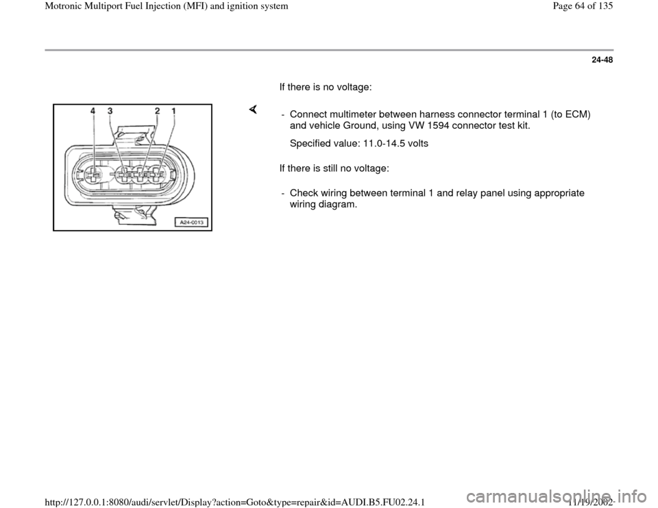
If there is no voltage:
If there is still no voltage: - Connect multimeter between harness connector terminal 1 (to ECM)
and vehicle Ground, using VW 1594 connector test kit.
Specified value: 11.0-14.5 volts
- Check wiring between terminal 1 and relay panel using appropriate
wiring diagram.
Pa
ge 64 of 135 Motronic Multi
port Fuel In
jection
(MFI
) and i
gnition s
ystem
11/19/2002 htt
p://127.0.0.1:8080/audi/servlet/Dis
play?action=Goto&t
yp
e=re
pair&id=AUDI.B5.FU02.24.1
Page 110 of 135
24-81
Fuel pump relay and connections,
checking
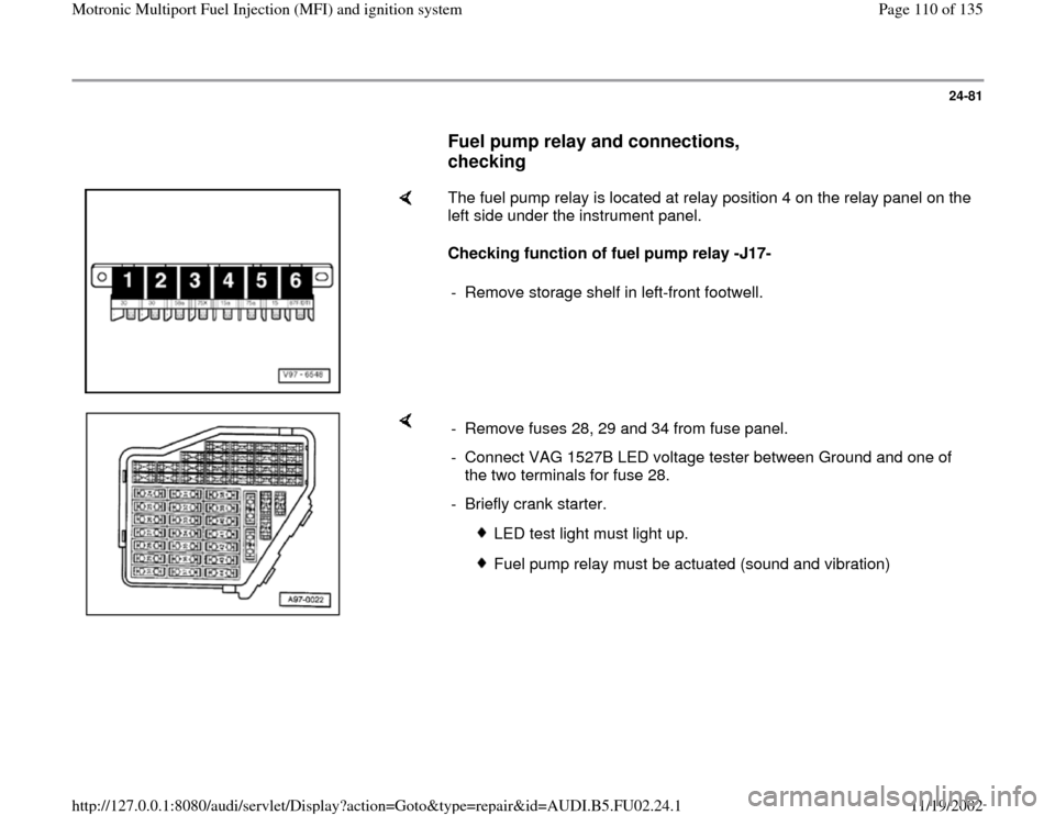
The fuel pump relay is located at relay position 4 on the relay panel on the
left side under the instrument panel.
Checking function of fuel pump relay -J17-
- Remove storage shelf in left-front footwell.
- Remove fuses 28, 29 and 34 from fuse panel.
- Connect VAG 1527B LED voltage tester between Ground and one of
the two terminals for fuse 28.
- Briefly crank starter.
LED test light must light up.
Fuel pump relay must be actuated (sound and vibration)
Pa
ge 110 of 135 Motronic Multi
port Fuel In
jection
(MFI
) and i
gnition s
ystem
11/19/2002 htt
p://127.0.0.1:8080/audi/servlet/Dis
play?action=Goto&t
yp
e=re
pair&id=AUDI.B5.FU02.24.1
Page 111 of 135
24-82
If the fuel pump does not respond:
- Check power supply wiring Page 24
-84
.
If the LED test light does not light up:
- Repeat test at other terminal of fuse 28.
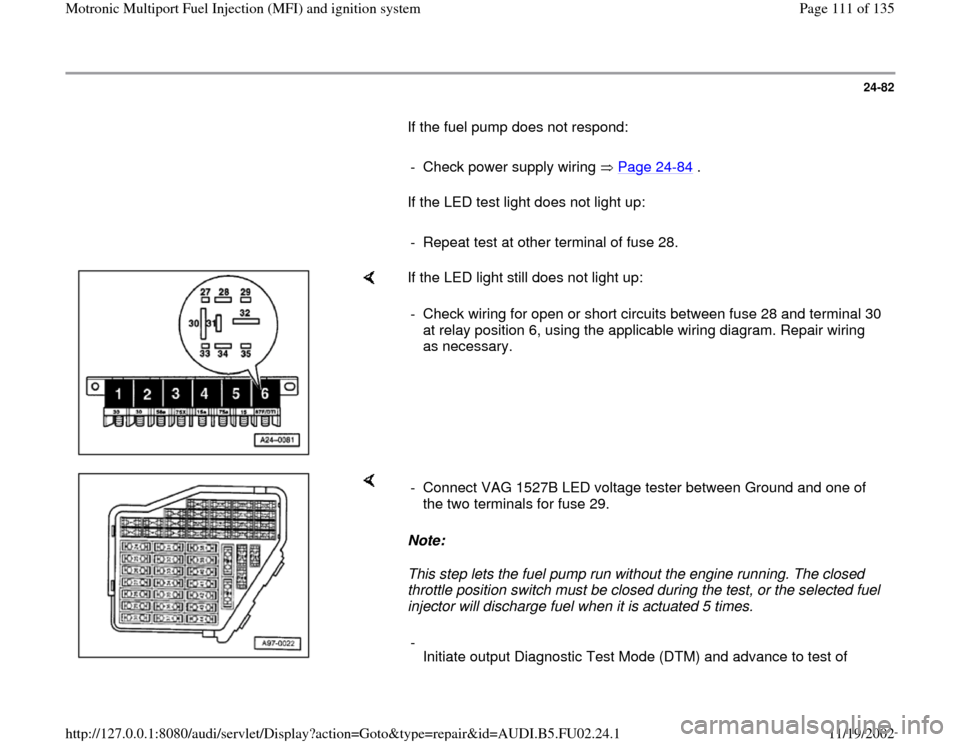
If the LED light still does not light up:
- Check wiring for open or short circuits between fuse 28 and terminal 30
at relay position 6, using the applicable wiring diagram. Repair wiring
as necessary.
Note:
This step lets the fuel pump run without the engine running. The closed
throttle position switch must be closed during the test, or the selected fuel
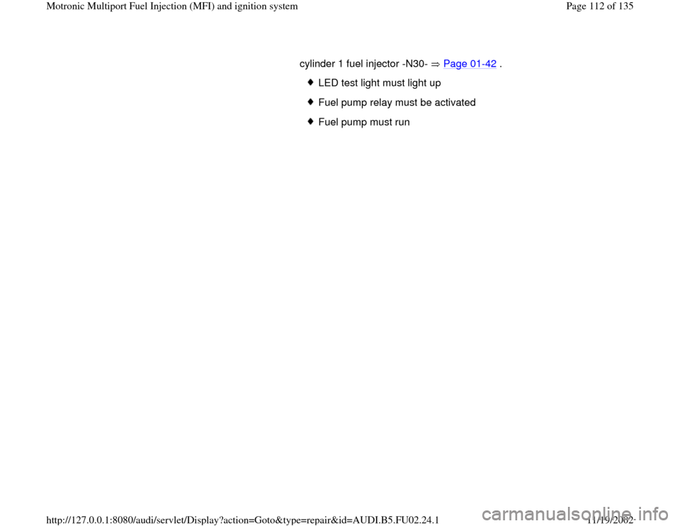
injector will discharge fuel when it is actuated 5 times. - Connect VAG 1527B LED voltage tester between Ground and one of
the two terminals for fuse 29.
-
Initiate output Diagnostic Test Mode (DTM) and advance to test of
Pa
ge 111 of 135 Motronic Multi
port Fuel In
jection
(MFI
) and i
gnition s
ystem
11/19/2002 htt
p://127.0.0.1:8080/audi/servlet/Dis
play?action=Goto&t
yp
e=re
pair&id=AUDI.B5.FU02.24.1
Page 112 of 135
cylinder 1 fuel injector -N30- Page 01
-42
.
LED test light must light up
Fuel pump relay must be activated
Fuel pump must run
Pa
ge 112 of 135 Motronic Multi
port Fuel In
jection
(MFI
) and i
gnition s
ystem
11/19/2002 htt
p://127.0.0.1:8080/audi/servlet/Dis
play?action=Goto&t
yp
e=re
pair&id=AUDI.B5.FU02.24.1
Page 113 of 135
24-83
If the LED test light does not light up:
- Repeat test at other terminal of fuse 29.
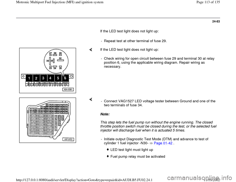
If the LED test light does not light up:
- Check wiring for open circuit between fuse 29 and terminal 30 at relay
position 6, using the applicable wiring diagram. Repair wiring as
necessary.
Note:
This step lets the fuel pump run without the engine running. The closed
throttle position switch must be closed during the test, or the selected fuel
injector will discharge fuel when it is actuated 5 times. - Connect VAG1527 LED voltage tester between Ground and one of the
two terminals of fuse 34.
- Initiate output Diagnostic Test Mode (DTM) and advance to test of
cylinder 1 fuel injector -N30- Page 01
-42
.
LED test light must light up
Fuel pump relay must be activated
Pa
ge 113 of 135 Motronic Multi
port Fuel In
jection
(MFI
) and i
gnition s
ystem
11/19/2002 htt
p://127.0.0.1:8080/audi/servlet/Dis
play?action=Goto&t
yp
e=re
pair&id=AUDI.B5.FU02.24.1
Page 115 of 135
24-84
If the LED test light does not light up:
- Repeat test at other terminal of fuse 34.
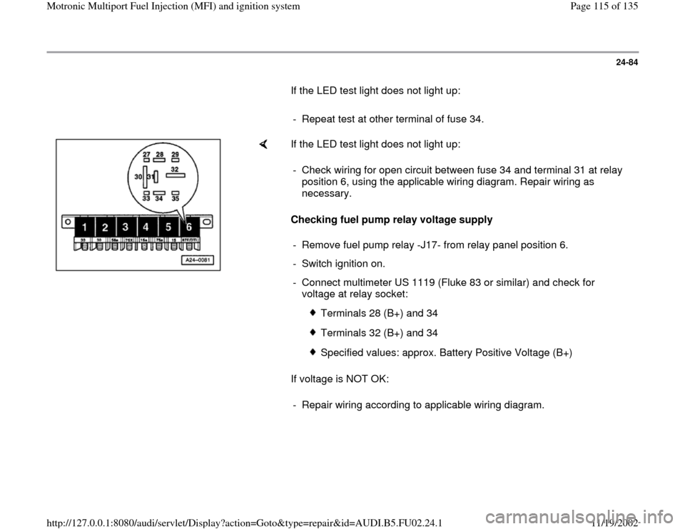
If the LED test light does not light up:
Checking fuel pump relay voltage supply
If voltage is NOT OK: - Check wiring for open circuit between fuse 34 and terminal 31 at relay
position 6, using the applicable wiring diagram. Repair wiring as
necessary.
- Remove fuel pump relay -J17- from relay panel position 6.
- Switch ignition on.
- Connect multimeter US 1119 (Fluke 83 or similar) and check for
voltage at relay socket:
Terminals 28 (B+) and 34
Terminals 32 (B+) and 34
Specified values: approx. Battery Positive Voltage (B+)
- Repair wiring according to applicable wiring diagram.
Pa
ge 115 of 135 Motronic Multi
port Fuel In
jection
(MFI
) and i
gnition s
ystem
11/19/2002 htt
p://127.0.0.1:8080/audi/servlet/Dis
play?action=Goto&t
yp
e=re
pair&id=AUDI.B5.FU02.24.1
Page 116 of 135
24-85
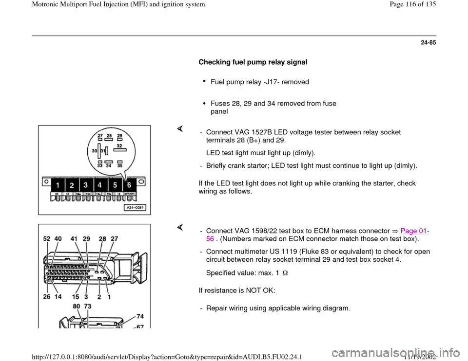
Checking fuel pump relay signal
Fuel pump relay -J17- removed
Fuses 28, 29 and 34 removed from fuse
panel
If the LED test light does not light up while cranking the starter, check
wiring as follows. - Connect VAG 1527B LED voltage tester between relay socket
terminals 28 (B+) and 29.
LED test light must light up (dimly).
- Briefly crank starter; LED test light must continue to light up (dimly).
If resistance is NOT OK: - Connect VAG 1598/22 test box to ECM harness connector Page 01
-
56
. (Numbers marked on ECM connector match those on test box).
- Connect multimeter US 1119 (Fluke 83 or equivalent) to check for open
circuit between relay socket terminal 29 and test box socket 4.
Specified value: max. 1 - Repair wiring using applicable wiring diagram.
Pa
ge 116 of 135 Motronic Multi
port Fuel In
jection
(MFI
) and i
gnition s
ystem
11/19/2002 htt
p://127.0.0.1:8080/audi/servlet/Dis
play?action=Goto&t
yp
e=re
pair&id=AUDI.B5.FU02.24.1
Page 118 of 135
24-86
If the wiring is OK, but the LED test light does not
light up:
- Replace Engine Control Module (ECM) Page
01
-57
.
If the wiring is OK, and the signal to the fuel
pump relay is OK:
- Replace fuel pump relay -J17-.
- Reinstall fuses.
Pa
ge 118 of 135 Motronic Multi
port Fuel In
jection
(MFI
) and i
gnition s
ystem
11/19/2002 htt
p://127.0.0.1:8080/audi/servlet/Dis
play?action=Goto&t
yp
e=re
pair&id=AUDI.B5.FU02.24.1