engine AUDI A4 1996 B5 / 1.G AFC Engine Cylinder Block Crankshaft And Flywheel Component Assembly Manual
[x] Cancel search | Manufacturer: AUDI, Model Year: 1996, Model line: A4, Model: AUDI A4 1996 B5 / 1.GPages: 32, PDF Size: 0.44 MB
Page 5 of 32

13-8
12 -
Dual mass flywheel or drive plate
Removing and installing, installation
dimensions page 13
-17
Removing and installing pilot needle
bearing page 13
-16
Adjusting engine speed (RPM) sensor
bracket -G28- page 13
-20
13 -
Main bearing shell
Checking radial clearance page 13
-21
14 -
Seal
Replacing page 13
-14
15 -
10 Nm (7 ft lb)
16 -
25 Nm (18 ft lb)
Thread bolts in hand-tight before tightening
crankshaft main bearing caps
17 -
Cylinder block
Pa
ge 5 of 32 C
ylinder block, crankshaft and fl
ywheel, com
ponent la
yout
11/21/2002 htt
p://127.0.0.1:8080/audi/servlet/Dis
play?action=Goto&t
yp
e=re
pair&id=AUDI.B5.GE01.13.4
Page 6 of 32
13-9
Ribbed belt, removing and installing
CAUTION!
Mark the direction of belt travel before
removing, using a crayon or marker.
Reinstalling a used belt in the opposite
direction could damage the belt.
Removing
- Remove engine and ribbed-belt guard.
- Loosen ribbed-belt tensioner using 17 mm
wrench and secure with locking drift 3204.
- Remove ribbed belt.
Installing
- Install ribbed belt over the crankshaft belt pulley
and guide pulley first, and then push it onto the
tensioning pulley.
- Remove locking drift 3204.
- Install engine and ribbed belt guard.
Routing of ribbed belt drive -D-
Pa
ge 6 of 32 C
ylinder block, crankshaft and fl
ywheel, com
ponent la
yout
11/21/2002 htt
p://127.0.0.1:8080/audi/servlet/Dis
play?action=Goto&t
yp
e=re
pair&id=AUDI.B5.GE01.13.4
Page 9 of 32
13-11
Toothed belt, removing and installing
Removing
CAUTION!
Mark the direction of belt travel before
removing, using a crayon or marker.
Reinstalling a used belt in the opposite
direction could damage the belt.
- Remove ribbed belt page 13
-9 .
- Unclip toothed belt guard on both sides.
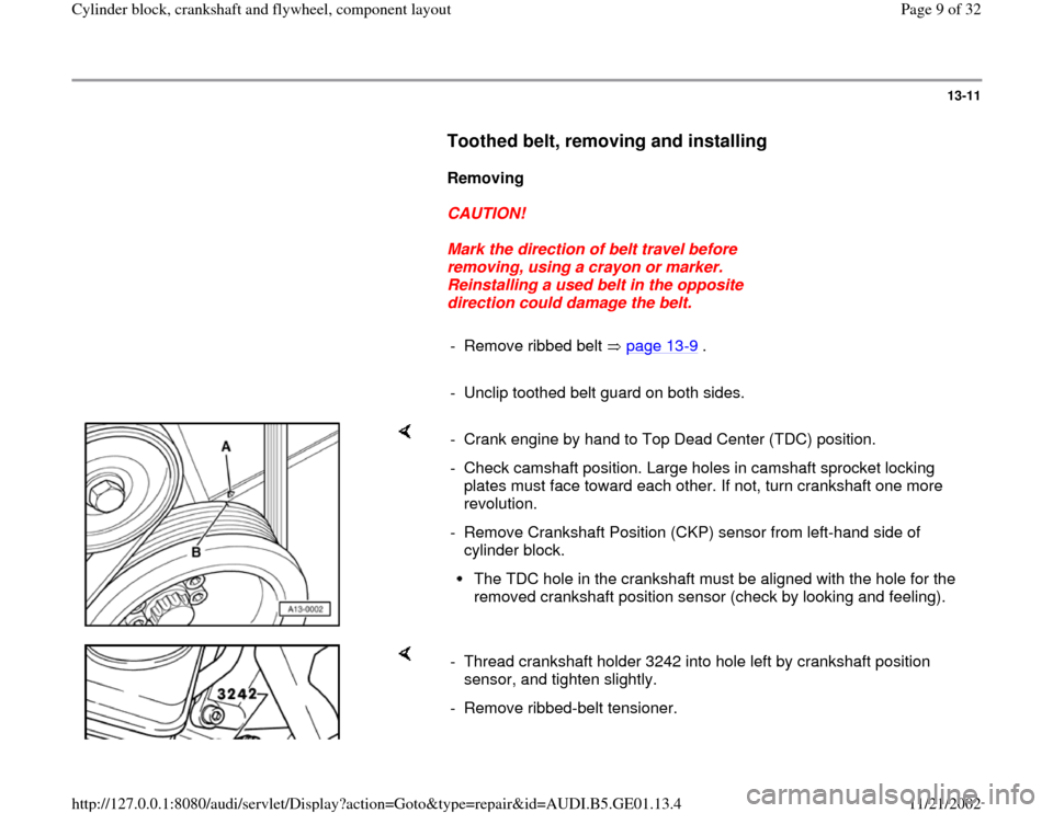
- Crank engine by hand to Top Dead Center (TDC) position.
- Check camshaft position. Large holes in camshaft sprocket locking
plates must face toward each other. If not, turn crankshaft one more
revolution.
- Remove Crankshaft Position (CKP) sensor from left-hand side of
cylinder block.
The TDC hole in the crankshaft must be aligned with the hole for the
removed crankshaft position sensor (check by looking and feeling).
- Thread crankshaft holder 3242 into hole left by crankshaft position
sensor, and tighten slightly.
- Remove ribbed-belt tensioner.
Pa
ge 9 of 32 C
ylinder block, crankshaft and fl
ywheel, com
ponent la
yout
11/21/2002 htt
p://127.0.0.1:8080/audi/servlet/Dis
play?action=Goto&t
yp
e=re
pair&id=AUDI.B5.GE01.13.4
Page 15 of 32
13-15
Flywheel/drive plate end (rear)
CAUTION!
Always replace the seal with the flange, if
available. Drain engine coolant before
removing flange ( Repair Group 19).
Replace only seal as described below if oil
seal with flange is not available.
- Remove clutch and flywheel, or drive plate, as
necessary.
Note:
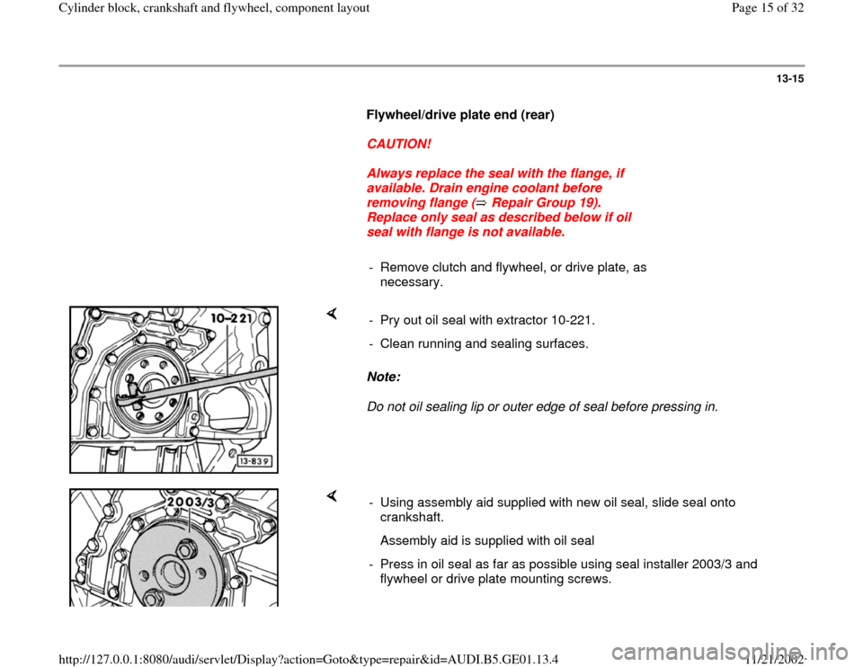
Do not oil sealing lip or outer edge of seal before pressing in. - Pry out oil seal with extractor 10-221.
- Clean running and sealing surfaces.
- Using assembly aid supplied with new oil seal, slide seal onto
crankshaft.
Assembly aid is supplied with oil seal
- Press in oil seal as far as possible using seal installer 2003/3 and
flywheel or drive plate mounting screws.
Pa
ge 15 of 32 C
ylinder block, crankshaft and fl
ywheel, com
ponent la
yout
11/21/2002 htt
p://127.0.0.1:8080/audi/servlet/Dis
play?action=Goto&t
yp
e=re
pair&id=AUDI.B5.GE01.13.4
Page 17 of 32
13-17
Dual mass flywheel or drive plate,
removing and installing
Flywheel
Note:
The needle roller bearing is in the flywheel and must be pressed in when
replacing the flywheel.
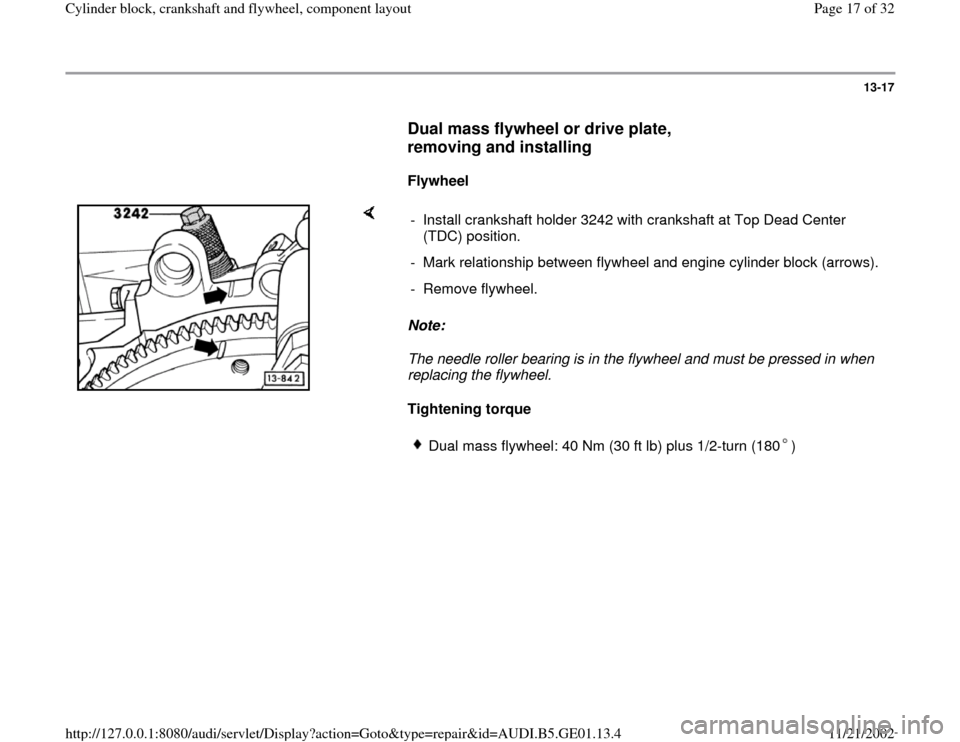
Tightening torque - Install crankshaft holder 3242 with crankshaft at Top Dead Center
(TDC) position.
- Mark relationship between flywheel and engine cylinder block (arrows).
- Remove flywheel.
Dual mass flywheel: 40 Nm (30 ft lb) plus 1/2-turn (180 )
Pa
ge 17 of 32 C
ylinder block, crankshaft and fl
ywheel, com
ponent la
yout
11/21/2002 htt
p://127.0.0.1:8080/audi/servlet/Dis
play?action=Goto&t
yp
e=re
pair&id=AUDI.B5.GE01.13.4
Page 19 of 32
13-19
Note:
Before installing the engine, make sure that the engine-to-transmission
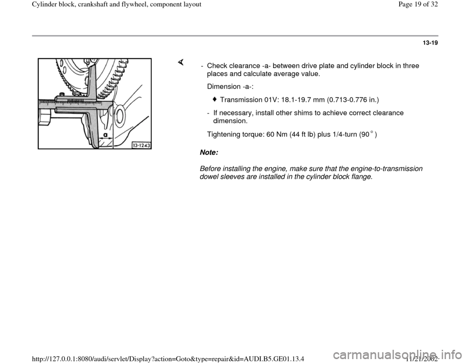
dowel sleeves are installed in the cylinder block flange. - Check clearance -a- between drive plate and cylinder block in three
places and calculate average value.
Dimension -a-:
Transmission 01V: 18.1-19.7 mm (0.713-0.776 in.)
- If necessary, install other shims to achieve correct clearance
dimension.
Tightening torque: 60 Nm (44 ft lb) plus 1/4-turn (90 )
Pa
ge 19 of 32 C
ylinder block, crankshaft and fl
ywheel, com
ponent la
yout
11/21/2002 htt
p://127.0.0.1:8080/audi/servlet/Dis
play?action=Goto&t
yp
e=re
pair&id=AUDI.B5.GE01.13.4
Page 20 of 32
13-20
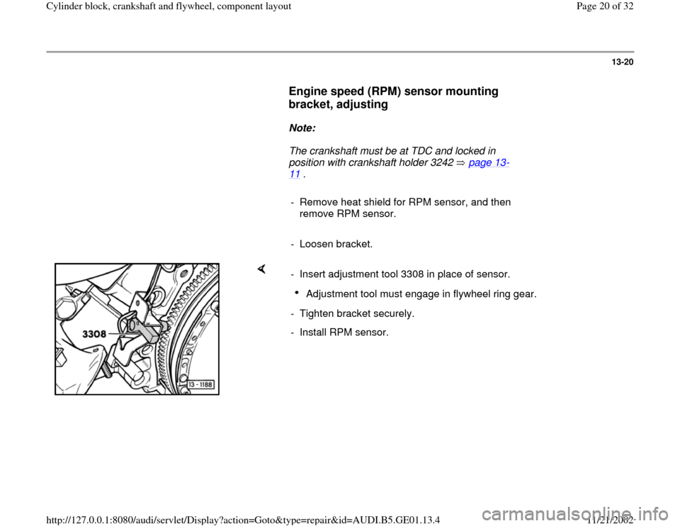
Engine speed (RPM) sensor mounting
bracket, adjusting
Note:
The crankshaft must be at TDC and locked in
position with crankshaft holder 3242 page 13
-
11
.
- Remove heat shield for RPM sensor, and then
remove RPM sensor.
- Loosen bracket.
- Insert adjustment tool 3308 in place of sensor.
Adjustment tool must engage in flywheel ring gear.
- Tighten bracket securely.
- Install RPM sensor.
Pa
ge 20 of 32 C
ylinder block, crankshaft and fl
ywheel, com
ponent la
yout
11/21/2002 htt
p://127.0.0.1:8080/audi/servlet/Dis
play?action=Goto&t
yp
e=re
pair&id=AUDI.B5.GE01.13.4