display AUDI A4 1996 B5 / 1.G AFC Engine On Board Diagnostic Multiport Fuel Injection Workshop Manual
[x] Cancel search | Manufacturer: AUDI, Model Year: 1996, Model line: A4, Model: AUDI A4 1996 B5 / 1.GPages: 366, PDF Size: 1.21 MB
Page 279 of 366
01-198
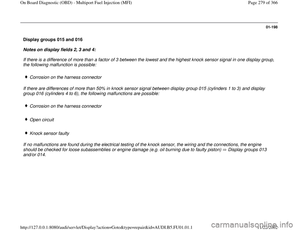
Display groups 015 and 016
Notes on display fields 2, 3 and 4:
If there is a difference of more than a factor of 3 between the lowest and the highest knock sensor signal in one display group,
the following malfunction is possible:
Corrosion on the harness connector
If there are differences of more than 50% in knock sensor signal between display group 015 (cylinders 1 to 3) and display
group 016 (cylinders 4 to 6), the following malfunctions are possible:
Corrosion on the harness connector
Open circuit
Knock sensor faulty
If no malfunctions are found during the electrical testing of the knock sensor, the wiring and the connections, the engine
should be checked for loose subassemblies or engine damage (e.g. oil burning due to faulty piston) Display groups 013
and/or 014.
Pa
ge 279 of 366 On Board Dia
gnostic
(OBD
) - Multi
port Fuel In
jection
(MFI
)
11/22/2002 htt
p://127.0.0.1:8080/audi/servlet/Dis
play?action=Goto&t
yp
e=re
pair&id=AUDI.B5.FU01.01.1
Page 280 of 366
01-199
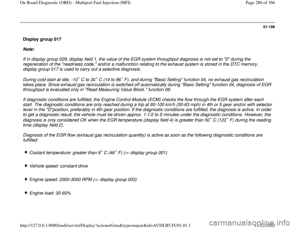
Display group 017
Note:
If in display group 029, display field 1, the value of the EGR system throughput diagnosis is not set to "0" during the
regeneration of the "readiness code," and/or a malfunction relating to the exhaust system is stored in the DTC memory,
display group 017 is used to carry out a selective diagnosis.
During cold start at idle, -10 C to 30 C (14 to 86 F), and during "Basic Setting" function 04, no exhaust gas recirculation
takes place. Since exhaust gas recirculation is switched off automatically during "Basic Setting" function 04, diagnosis of EGR
throughput is evaluated only in "Read Measuring Value Block." function 08. If diagnostic conditions are fulfilled, the Engine Control Module (ECM) checks the flow through the EGR system after each
start. The diagnostic conditions are only reached during a trip at 80-100 km/h (50-63 mph) in 4th or 5 gear and/or with selector
lever in the "D"position, preferably in 4th gear position. If the diagnostic conditions are fulfilled, the diagnosis is active. In order
to get a diagnostic result, the vehicle must be driven approx. 1-1/2 to 5 minutes under the diagnostic conditions. However, the
diagnosis is only considered OK when the EGR temperature (display field 4) is greater than 50 C (122 F) during the reading
time (display field 2). Diagnosis of the EGR flow (exhaust gas recirculation quantity) is active as soon as the following diagnostic conditions are
fulfilled:
Coolant temperature: greater than 8 C (46 F) ( display group 001) Vehicle speed: constant drive
Engine speed: 2000-3000 RPM ( display group 003) Engine load: 30-60%
Pa
ge 280 of 366 On Board Dia
gnostic
(OBD
) - Multi
port Fuel In
jection
(MFI
)
11/22/2002 htt
p://127.0.0.1:8080/audi/servlet/Dis
play?action=Goto&t
yp
e=re
pair&id=AUDI.B5.FU01.01.1
Page 281 of 366

01-200
Display shows
Specified display value
Designation
Basic setting 17
1 2 3 4 0 - 1 1 = Timer 1 (final value = 1)
0 - 225 2 = Timer 2 (final value = 48 or 160)
30% - 60% 3 = Momentary engine load
0C - 255C
4 = Exhaust gas recirculation temperature (EGR temperature sensor -G98-)
Notes on display fields 1 and 2:
In display fields 1 and 2, the timers are displayed. The final value of timer 2 is "48" or "160". The final values "48" and
"160" are reading times ("48" = reading time 1; "160" = reading time 2).
If the diagnostic conditions are fulfilled, the timers are incremented, outside the diagnostic conditions they are
decremented.
Counter 1 is incremented by "1" as soon as counter 2 reaches the value "255." If the value 255 is reached, counter 2 goes
back to "0" and starts to increment again up to "48" (reading time 1).
If reading time 1 has been reached, the Engine Control Module (ECM) -J192- checks the EGR temperature (display field
4). If the EGR temperature is greater than 50 C (122 F), the diagnosis is OK and the diagnostic program is discontinued.
If the EGR temperature during reading time 1 is less than 50 C (122 F),counter 2 counts up to "160"(reading time 2). When reading time 2 is reached, the -J192- checks the EGR temperature (display field 4) again. If the EGR temperature is
now greater than 50 C (122 F), the diagnosis is OK and the diagnostic program will be discontinued. If the EGR
temperature is again less than 50 C (122 F), the EGR flow test is carried out again.
Pa
ge 281 of 366 On Board Dia
gnostic
(OBD
) - Multi
port Fuel In
jection
(MFI
)
11/22/2002 htt
p://127.0.0.1:8080/audi/servlet/Dis
play?action=Goto&t
yp
e=re
pair&id=AUDI.B5.FU01.01.1
Page 283 of 366
01-201
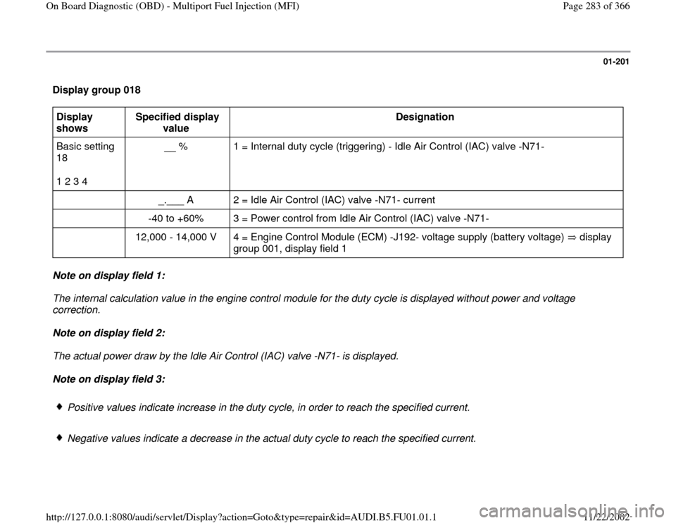
Display group 018 Display
shows Specified display
value Designation
Basic setting
18
1 2 3 4 __ % 1 = Internal duty cycle (triggering) - Idle Air Control (IAC) valve -N71-
_.___ A 2 = Idle Air Control (IAC) valve -N71- current
-40 to +60% 3 = Power control from Idle Air Control (IAC) valve -N71-
12,000 - 14,000 V 4 = Engine Control Module (ECM) -J192- voltage supply (battery voltage) display
group 001, display field 1 Note on display field 1:
The internal calculation value in the engine control module for the duty cycle is displayed without power and voltage
correction.
Note on display field 2:
The actual power draw by the Idle Air Control (IAC) valve -N71- is displayed.
Note on display field 3:
Positive values indicate increase in the duty cycle, in order to reach the specified current.
Negative values indicate a decrease in the actual duty cycle to reach the specified current.
Pa
ge 283 of 366 On Board Dia
gnostic
(OBD
) - Multi
port Fuel In
jection
(MFI
)
11/22/2002 htt
p://127.0.0.1:8080/audi/servlet/Dis
play?action=Goto&t
yp
e=re
pair&id=AUDI.B5.FU01.01.1
Page 284 of 366

If +60% is displayed for a longer time , this indicates contact resistance and/or an adjuster that is too hot.
If -40% is displayed for a longer time, this indicates a winding short in the idle adjuster.
Pa
ge 284 of 366 On Board Dia
gnostic
(OBD
) - Multi
port Fuel In
jection
(MFI
)
11/22/2002 htt
p://127.0.0.1:8080/audi/servlet/Dis
play?action=Goto&t
yp
e=re
pair&id=AUDI.B5.FU01.01.1
Page 285 of 366

01-202
Display group 019 Display shows
Specified display value
Designation/diagnose
Basic setting 19
1 2 3 4 At idle: 1.5 - 3.5% 1 = Momentary engine power (internal computation value)
At 2500 RPM:
6.5 - 9.5%
At idle:
3.0 - 5.5 g/s 2 = Intake air quantity (via mass air flow sensor)
At 2500 RPM:
9.5 - 13.5 g/s
___ km/h 3 = Momentary vehicle speed display group 003, display field 4 _._ m/s 4 = Fuel injection time (average of all cylinders) Note on display field 1:
The momentary engine power is a control module-internal calculated value that is calculated from the amount of air taken in
under normal conditions (air pressure 1013 mbar, air temperature 20 C or 68 F).
Pa
ge 285 of 366 On Board Dia
gnostic
(OBD
) - Multi
port Fuel In
jection
(MFI
)
11/22/2002 htt
p://127.0.0.1:8080/audi/servlet/Dis
play?action=Goto&t
yp
e=re
pair&id=AUDI.B5.FU01.01.1
Page 286 of 366

01-203
Display groups 020 and 021
Note:
Display groups 020 and 021 are only considered in vehicles with Secondary Air Injection (AIR) system. Display shows
Display/specified value
Designation/diagnose
Basic setting 20
1 2 3 4 0% 1 = Lean time of bank 1, HO2S 1 voltage signal
0% 2 = Lean time of bank 2, HO2S 1 voltage signal
69% 3 = Diagnosis limit value
00000000 4 = Diagnosis condition and/or result Display group 021 Display shows
Display/specified value
Designation/diagnose
Basic setting 21
1 2 3 4 0.0% 1 = Oxygen sensor control, bank 1 richens
0.0% 1 = Oxygen sensor control, bank 2 richens
14.0% 3 = Diagnosis limit value
00000000 4 = Diagnosis condition and/or result
Pa
ge 286 of 366 On Board Dia
gnostic
(OBD
) - Multi
port Fuel In
jection
(MFI
)
11/22/2002 htt
p://127.0.0.1:8080/audi/servlet/Dis
play?action=Goto&t
yp
e=re
pair&id=AUDI.B5.FU01.01.1
Page 287 of 366
01-204
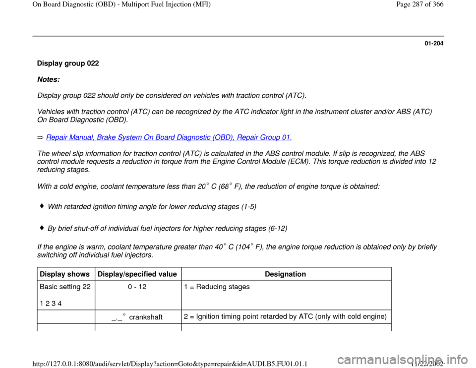
Display group 022
Notes:
Display group 022 should only be considered on vehicles with traction control (ATC).
Vehicles with traction control (ATC) can be recognized by the ATC indicator light in the instrument cluster and/or ABS (ATC)
On Board Diagnostic (OBD).
Repair Manual, Brake System On Board Diagnostic (OBD), Repair Group 01.
The wheel slip information for traction control (ATC) is calculated in the ABS control module. If slip is recognized, the ABS
control module requests a reduction in torque from the Engine Control Module (ECM). This torque reduction is divided into 12
reducing stages.
With a cold engine, coolant temperature less than 20 C (68 F), the reduction of engine torque is obtained:
With retarded ignition timing angle for lower reducing stages (1-5)
By brief shut-off of individual fuel injectors for higher reducing stages (6-12)
If the engine is warm, coolant temperature greater than 40 C (104 F), the engine torque reduction is obtained only by briefly
switching off individual fuel injectors.
Display shows
Display/specified value
Designation
Basic setting 22
1 2 3 4 0 - 12 1 = Reducing stages
_._ crankshaft
2 = Ignition timing point retarded by ATC (only with cold engine)
Pa
ge 287 of 366 On Board Dia
gnostic
(OBD
) - Multi
port Fuel In
jection
(MFI
)
11/22/2002 htt
p://127.0.0.1:8080/audi/servlet/Dis
play?action=Goto&t
yp
e=re
pair&id=AUDI.B5.FU01.01.1
Page 289 of 366
01-205
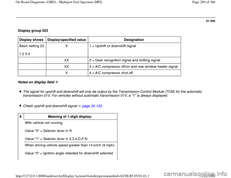
Display group 023 Display shows
Display/specified value
Designation
Basic setting 23
1 2 3 4 X 1 = Upshift or downshift signal
XX 2 = Gear recognition signal and shifting signal
XX 3 = A/C compressor off/on and rear window heater signal
X 4 = A/C compressor shut-off Notes on display field 1:
The signal for upshift and downshift will only be output by the Transmission Control Module (TCM) for the automatic
transmission 01V. For vehicles without automatic transmission 01V, a "1" is always displayed.
Check upshift and downshift signal page 24
-103
.
X
Meaning of 1-digit display:
With vehicle not running:
Value "0" = Selector lever in R
Value "1" = Selector lever in 2,3,4,D,P,N
When driving-vehicle speed greater than 14 km/h (9 mph):
Value "0" = Ignition angle retarded for downshift selected
Pa
ge 289 of 366 On Board Dia
gnostic
(OBD
) - Multi
port Fuel In
jection
(MFI
)
11/22/2002 htt
p://127.0.0.1:8080/audi/servlet/Dis
play?action=Goto&t
yp
e=re
pair&id=AUDI.B5.FU01.01.1
Page 291 of 366
01-206
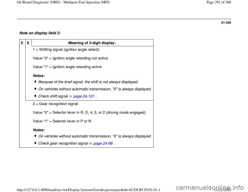
Note on display field 2: X
X
Meaning of 2-digit display:
1 = Shifting signal (ignition angle retard):
Value "0" = Ignition angle retarding not active
Value "1" = Ignition angle retarding active
Notes:
Because of the brief signal, the shift is not always displayed.
On vehicles without automatic transmission, "0" is always displayed.
Check shift signal page 24
-101
.
2 = Gear recognition signal:
Value "0" = Selector lever in R, D, 4, 3, or 2 (driving mode engaged)
Value "1" = Selector lever in P or N
Notes:
On vehicles without automatic transmission, "0" is always displayed.
Check gear recognition signal page 24
-99
.
Pa
ge 291 of 366 On Board Dia
gnostic
(OBD
) - Multi
port Fuel In
jection
(MFI
)
11/22/2002 htt
p://127.0.0.1:8080/audi/servlet/Dis
play?action=Goto&t
yp
e=re
pair&id=AUDI.B5.FU01.01.1