check engine AUDI A4 1996 B5 / 1.G AHA Engine Auxiliary Signals Checking Workshop Manual
[x] Cancel search | Manufacturer: AUDI, Model Year: 1996, Model line: A4, Model: AUDI A4 1996 B5 / 1.GPages: 22, PDF Size: 0.09 MB
Page 3 of 22
24-165
Checking
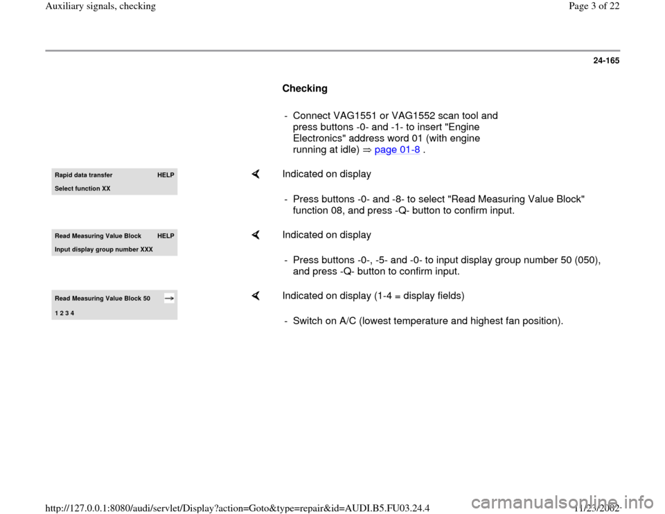
- Connect VAG1551 or VAG1552 scan tool and
press buttons -0- and -1- to insert "Engine
Electronics" address word 01 (with engine
running at idle) page 01
-8 .
Rapid data transfer
HELP
Select function XX
Indicated on display
- Press buttons -0- and -8- to select "Read Measuring Value Block"
function 08, and press -Q- button to confirm input.
Read Measurin
g Value Block
HELP
Input displa
y group number XXX
Indicated on display
- Press buttons -0-, -5- and -0- to input display group number 50 (050),
and press -Q- button to confirm input.
Read Measuring Value Block 50 1 2 3 4
Indicated on display (1-4 = display fields)
- Switch on A/C (lowest temperature and highest fan position).
Pa
ge 3 of 22 Auxiliar
y si
gnals, checkin
g
11/23/2002 htt
p://127.0.0.1:8080/audi/servlet/Dis
play?action=Goto&t
yp
e=re
pair&id=AUDI.B5.FU03.24.4
Page 4 of 22
24-166
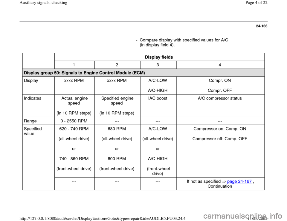
- Compare display with specified values for A/C
(in display field 4).
Display fields
1 2 3 4
Display group 50: Signals to Engine Control Module (ECM)
Display xxxx RPM xxxx RPM A/C-LOW
A/C-HIGH Compr. ON
Compr. OFF
Indicates Actual engine
speed
(in 10 RPM steps) Specified engine
speed
(in 10 RPM steps) IAC boost A/C compressor status
Range 0 - 2550 RPM --- --- ---
Specified
value 620 - 740 RPM
(all-wheel drive)
or
740 - 860 RPM
(front-wheel drive) 680 RPM
(all-wheel drive)
or
800 RPM
(front-wheel drive) A/C-LOW
(all-wheel drive)
or
A/C-HIGH
(front-wheel
drive) Compressor on: Comp. ON
Compressor off: Comp. OFF
--- --- --- If not as specified page 24
-167
,
Continuation
Pa
ge 4 of 22 Auxiliar
y si
gnals, checkin
g
11/23/2002 htt
p://127.0.0.1:8080/audi/servlet/Dis
play?action=Goto&t
yp
e=re
pair&id=AUDI.B5.FU03.24.4
Page 10 of 22
24-169
Test procedure
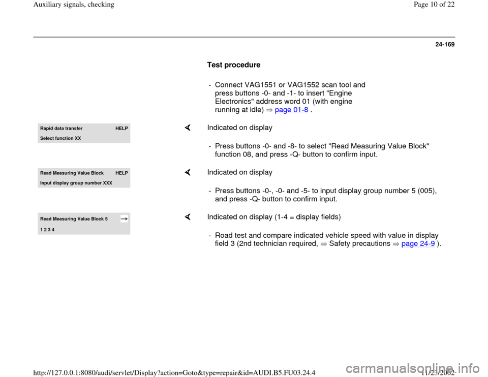
- Connect VAG1551 or VAG1552 scan tool and
press buttons -0- and -1- to insert "Engine
Electronics" address word 01 (with engine
running at idle) page 01
-8 .
Rapid data transfer
HELP
Select function XX
Indicated on display
- Press buttons -0- and -8- to select "Read Measuring Value Block"
function 08, and press -Q- button to confirm input.
Read Measurin
g Value Block
HELP
Input displa
y group number XXX
Indicated on display
- Press buttons -0-, -0- and -5- to input display group number 5 (005),
and press -Q- button to confirm input.
Read Measuring Value Block 5 1 2 3 4
Indicated on display (1-4 = display fields)
- Road test and compare indicated vehicle speed with value in display
field 3 (2nd technician required, Safety precautions page 24
-9 ).
Pa
ge 10 of 22 Auxiliar
y si
gnals, checkin
g
11/23/2002 htt
p://127.0.0.1:8080/audi/servlet/Dis
play?action=Goto&t
yp
e=re
pair&id=AUDI.B5.FU03.24.4
Page 11 of 22
24-170
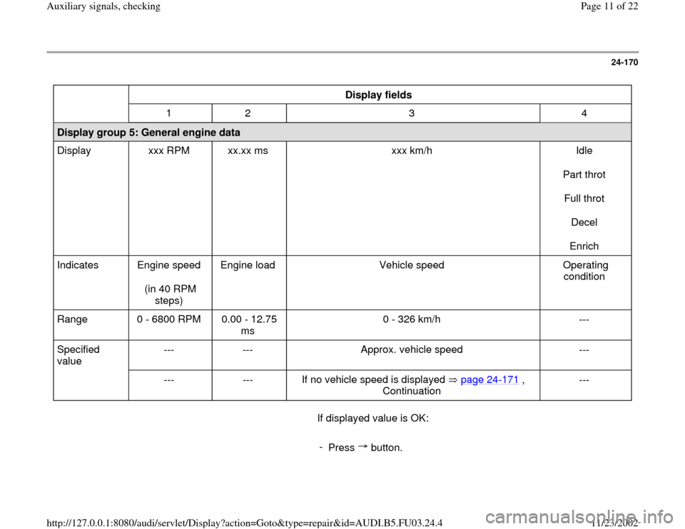
Display fields
1 2 3 4
Display group 5: General engine data
Display xxx RPM xx.xx ms xxx km/h Idle
Part throt
Full throt
Decel
Enrich
Indicates Engine speed
(in 40 RPM
steps) Engine load Vehicle speed Operating
condition
Range 0 - 6800 RPM 0.00 - 12.75
ms 0 - 326 km/h ---
Specified
value --- --- Approx. vehicle speed ---
--- --- If no vehicle speed is displayed page 24
-171
,
Continuation
---
If displayed value is OK:
-
Press button.
Pa
ge 11 of 22 Auxiliar
y si
gnals, checkin
g
11/23/2002 htt
p://127.0.0.1:8080/audi/servlet/Dis
play?action=Goto&t
yp
e=re
pair&id=AUDI.B5.FU03.24.4
Page 15 of 22
24-172
CAN-Bus, checking
When a CAN-Bus malfunction is indicated during
a check of DTC memory of the Engine Control
Module (ECM), refer to the following test to
eliminate the malfunction.
Note:
The information exchange occurs between the
Engine Control Module (ECM) and the
Transmission Control Module (TCM) via a CAN-
Bus.
All signals are carried by 2 wires between the
ECM and the TCM.
Required special tools and test equipment
VAG1551 or VAG1552 Scan Tool (ST) with
VAG1551/3 adapter cable
VAG1598/22 test box
VW1594 connector test kit
Wiring diagrams
Pa
ge 15 of 22 Auxiliar
y si
gnals, checkin
g
11/23/2002 htt
p://127.0.0.1:8080/audi/servlet/Dis
play?action=Goto&t
yp
e=re
pair&id=AUDI.B5.FU03.24.4
Page 16 of 22
24-173
Checking
- Check DTC memory of Transmission Control
Module (TCM).
Repair Manual, 5 Spd. Automatic
Transmission 01V, Repair Group 01 If a DTC regarding the CAN-Bus wire is also
stored in the TCM:
- Switch ignition off.
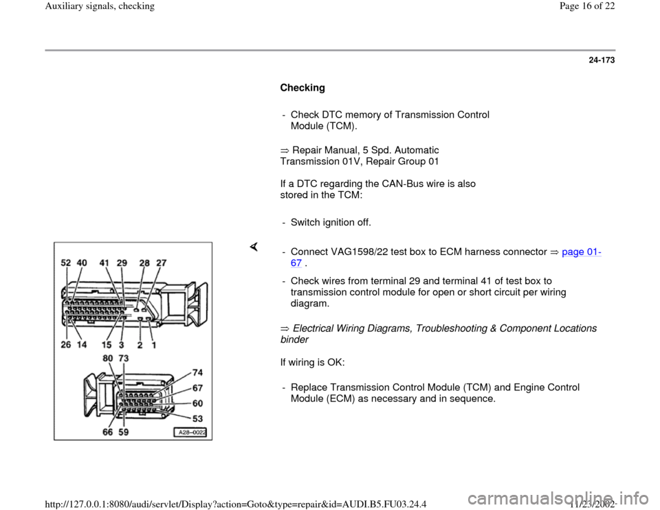
Electrical Wiring Diagrams, Troubleshooting & Component Locations
binder
If wiring is OK: - Connect VAG1598/22 test box to ECM harness connector page 01
-
67
.
- Check wires from terminal 29 and terminal 41 of test box to
transmission control module for open or short circuit per wiring
diagram. - Replace Transmission Control Module (TCM) and Engine Control
Module (ECM) as necessary and in sequence.
Pa
ge 16 of 22 Auxiliar
y si
gnals, checkin
g
11/23/2002 htt
p://127.0.0.1:8080/audi/servlet/Dis
play?action=Goto&t
yp
e=re
pair&id=AUDI.B5.FU03.24.4
Page 17 of 22
24-174
Rough road signal from ABS/EDL
control module, checking
Notes:
When the ABS/EDL control module senses a
wheel spinning, it produces the rough road
signal. When the ECM recognizes the rough
road signal, the misfire recognition is switched
off.
Check the rough road signal only when the
trouble code 18014 "Rough Road Spec Engine
Torque ABS-ECU Electrical Malfunction" is
stored. The possible "Misfire" malfunction is in
this case a subsequent malfunction that can be
disregarded.
The wiring and the rough road signal are
monitored by the ECM.
Emissions testing on a front-wheel drive vehicle
with ABS/EDL, during which only the front
wheels turn while the rear wheels are
stationary, can result in the DTC 18014 being
stored in DTC memory. Therefore, the fuse for
the ABS/EDL control module must be removed.
After the test, check DTC memory for the
ABS/EDL control module and the ECM. Then
erase DTC memory.
Pa
ge 17 of 22 Auxiliar
y si
gnals, checkin
g
11/23/2002 htt
p://127.0.0.1:8080/audi/servlet/Dis
play?action=Goto&t
yp
e=re
pair&id=AUDI.B5.FU03.24.4