wiring diagram AUDI A4 1996 B5 / 1.G ATW Engine On Board Diagnostic Workshop Manual
[x] Cancel search | Manufacturer: AUDI, Model Year: 1996, Model line: A4, Model: AUDI A4 1996 B5 / 1.GPages: 19, PDF Size: 0.1 MB
Page 8 of 19
01-7
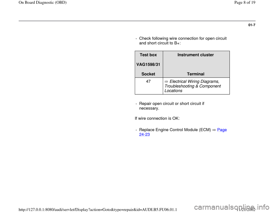
- Check following wire connection for open circuit
and short circuit to B+:
Test box
VAG1598/31
Socket
Instrument cluster
Terminal
47 Electrical Wiring Diagrams,
Troubleshooting & Component
Locations
- Repair open circuit or short circuit if
necessary.
If wire connection is OK:
- Replace Engine Control Module (ECM) Page
24
-23
Pa
ge 8 of 19 On Board Dia
gnostic
(OBD
)
11/21/2002 htt
p://127.0.0.1:8080/audi/servlet/Dis
play?action=Goto&t
yp
e=re
pair&id=AUDI.B5.FU06.01.1
Page 9 of 19
01-8
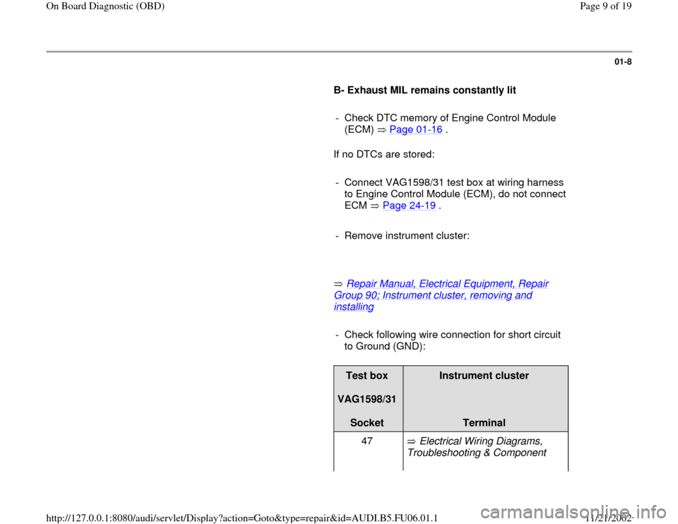
B- Exhaust MIL remains constantly lit
- Check DTC memory of Engine Control Module
(ECM) Page 01
-16
.
If no DTCs are stored:
- Connect VAG1598/31 test box at wiring harness
to Engine Control Module (ECM), do not connect
ECM Page 24
-19
.
- Remove instrument cluster:
Repair Manual, Electrical Equipment, Repair
Group 90; Instrument cluster, removing and installing
- Check following wire connection for short circuit
to Ground (GND):
Test box
VAG1598/31
Socket
Instrument cluster
Terminal
47 Electrical Wiring Diagrams,
Troubleshooting & Component
Pa
ge 9 of 19 On Board Dia
gnostic
(OBD
)
11/21/2002 htt
p://127.0.0.1:8080/audi/servlet/Dis
play?action=Goto&t
yp
e=re
pair&id=AUDI.B5.FU06.01.1
Page 12 of 19
01-10
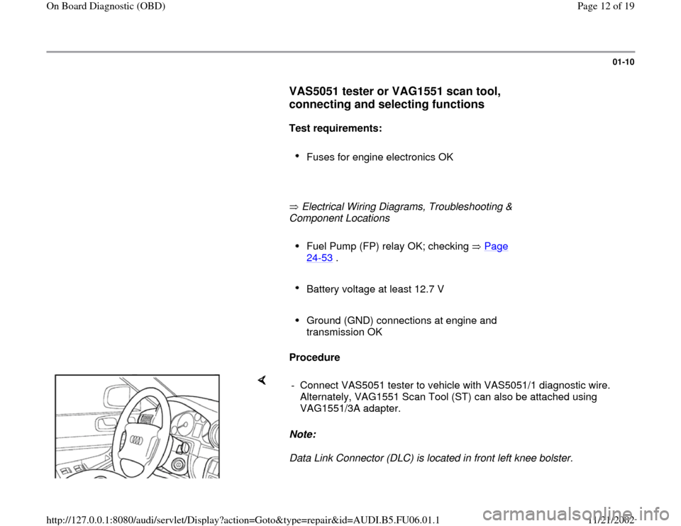
VAS5051 tester or VAG1551 scan tool,
connecting and selecting functions
Test requirements:
Fuses for engine electronics OK
Electrical Wiring Diagrams, Troubleshooting &
Component Locations
Fuel Pump (FP) relay OK; checking Page 24
-53
.
Battery voltage at least 12.7 V
Ground (GND) connections at engine and
transmission OK
Procedure
Note:
Data Link Connector (DLC) is located in front left knee bolster. - Connect VAS5051 tester to vehicle with VAS5051/1 diagnostic wire.
Alternately, VAG1551 Scan Tool (ST) can also be attached using
VAG1551/3A adapter.
Pa
ge 12 of 19 On Board Dia
gnostic
(OBD
)
11/21/2002 htt
p://127.0.0.1:8080/audi/servlet/Dis
play?action=Goto&t
yp
e=re
pair&id=AUDI.B5.FU06.01.1
Page 13 of 19
01-11
WARNING!
Observe safety precautions Page 01
-9 .
Note:
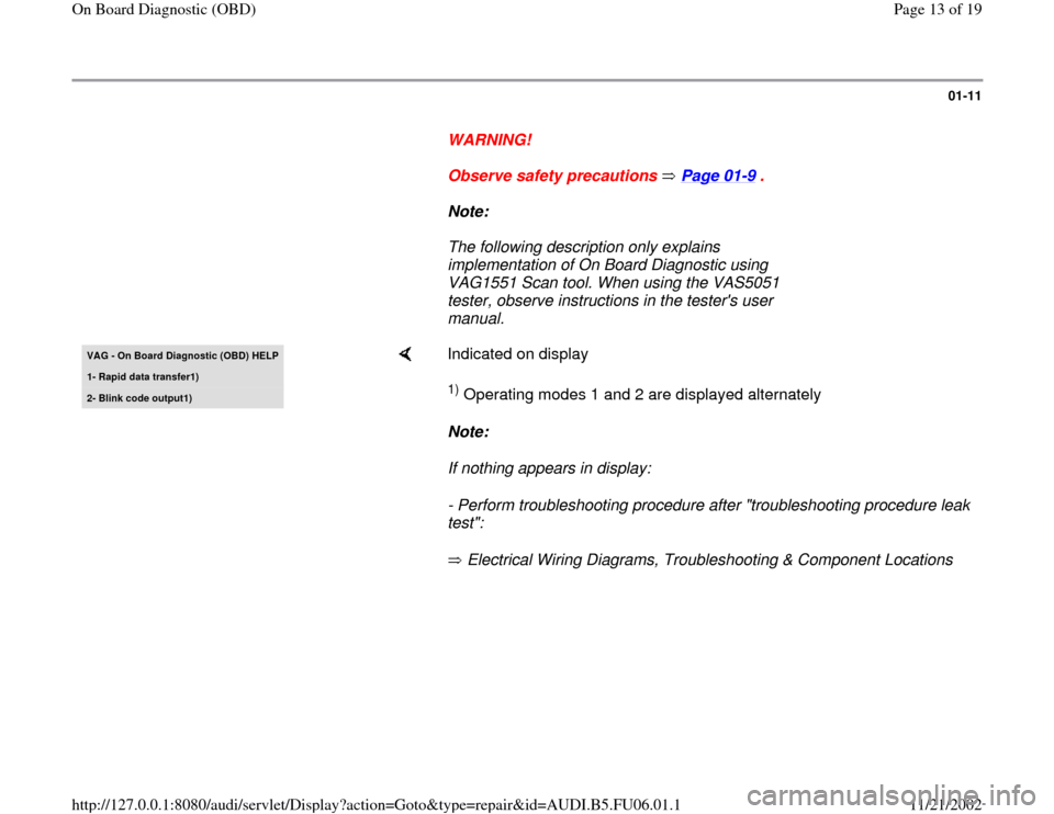
The following description only explains
implementation of On Board Diagnostic using
VAG1551 Scan tool. When using the VAS5051
tester, observe instructions in the tester's user
manual. VAG - On Board Diagnostic (OBD)
HELP
1- Rapid data transfer1
)
2- Blink code output1
)
Indicated on display 1) Operating modes 1 and 2 are displayed alternately
Note:
If nothing appears in display:
- Perform troubleshooting procedure after "troubleshooting procedure leak
test":
Electrical Wiring Diagrams, Troubleshooting & Component Locations
Pa
ge 13 of 19 On Board Dia
gnostic
(OBD
)
11/21/2002 htt
p://127.0.0.1:8080/audi/servlet/Dis
play?action=Goto&t
yp
e=re
pair&id=AUDI.B5.FU06.01.1
Page 17 of 19
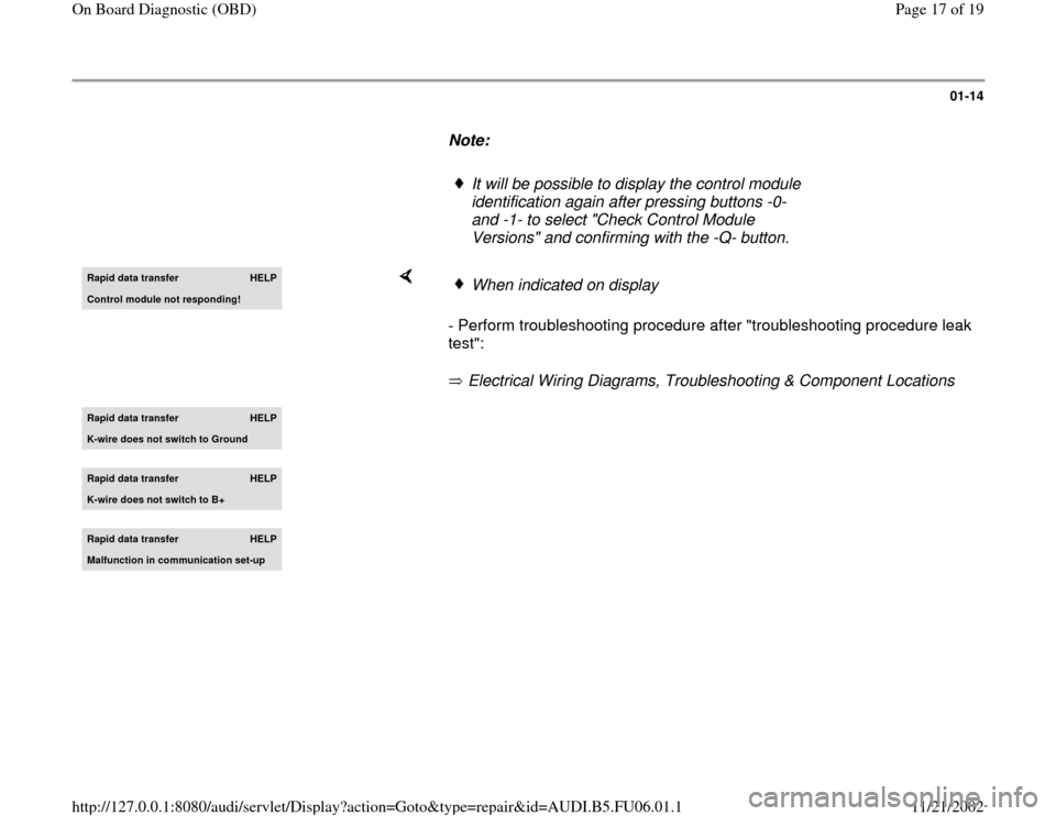
01-14
Note:
It will be possible to display the control module
identification again after pressing buttons -0-
and -1- to select "Check Control Module
Versions" and confirming with the -Q- button.
Rapid data transfer
HELP
Control module not respondin
g!
- Perform troubleshooting procedure after "troubleshooting procedure leak
test":
Electrical Wiring Diagrams, Troubleshooting & Component Locations
When indicated on display
Rapid data transfer
HELP
K-wire does not switch to Ground
Rapid data transfer
HELP
K-wire does not switch to B+
Rapid data transfer
HELP
Malfunction in communication set-up
Pa
ge 17 of 19 On Board Dia
gnostic
(OBD
)
11/21/2002 htt
p://127.0.0.1:8080/audi/servlet/Dis
play?action=Goto&t
yp
e=re
pair&id=AUDI.B5.FU06.01.1