coolant AUDI A4 1996 B5 / 1.G AWM Engine Cooling System Components User Guide
[x] Cancel search | Manufacturer: AUDI, Model Year: 1996, Model line: A4, Model: AUDI A4 1996 B5 / 1.GPages: 38, PDF Size: 0.7 MB
Page 15 of 38
19-12
Coolant pump, removing and installing
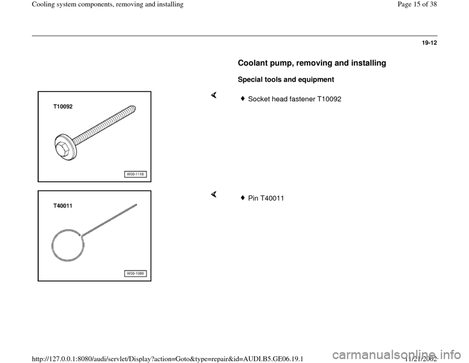
Special tools and equipment
Socket head fastener T10092
Pin T40011
Pa
ge 15 of 38 Coolin
g system com
ponents, removin
g and installin
g
11/21/2002 htt
p://127.0.0.1:8080/audi/servlet/Dis
play?action=Goto&t
yp
e=re
pair&id=AUDI.B5.GE06.19.1
Page 16 of 38
19-13
Removing
Engine in vehicle.
Lock carrier must be in service position
Page 13
-1 .
- Drain coolant Page 19
-4 .
- Remove ribbed belt and tensioner for ribbed belt
Page 13
-18
.
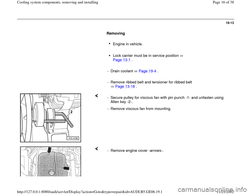
- Secure pulley for viscous fan with pin punch -1- and unfasten using
Allen key -2-.
- Remove viscous fan from mounting.
- Remove engine cover -arrows-.
Pa
ge 16 of 38 Coolin
g system com
ponents, removin
g and installin
g
11/21/2002 htt
p://127.0.0.1:8080/audi/servlet/Dis
play?action=Goto&t
yp
e=re
pair&id=AUDI.B5.GE06.19.1
Page 18 of 38
19-15
- Take toothed belt off camshaft sprocket and
coolant pump.
Note:
The vibration damper and lower toothed belt
guard do not have to be removed.
The toothed belt should be left in position on
the crankshaft sprocket.
Before removing the coolant pump, cover
toothed belt with a cloth to protect from coolant.
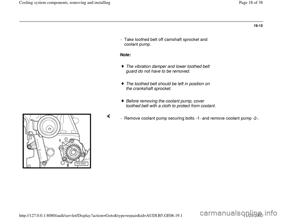
- Remove coolant pump securing bolts -1- and remove coolant pump -2-.
Pa
ge 18 of 38 Coolin
g system com
ponents, removin
g and installin
g
11/21/2002 htt
p://127.0.0.1:8080/audi/servlet/Dis
play?action=Goto&t
yp
e=re
pair&id=AUDI.B5.GE06.19.1
Page 19 of 38
19-16
Installing
Installation is carried out in the reverse order of
removal; note the following:
Note:
Always replace seals and gaskets.
- Clean and smooth down sealing surface for O-
ring as required.
Note:
Observe all instructions on removing and installing the toothed belt
Page 13
-40
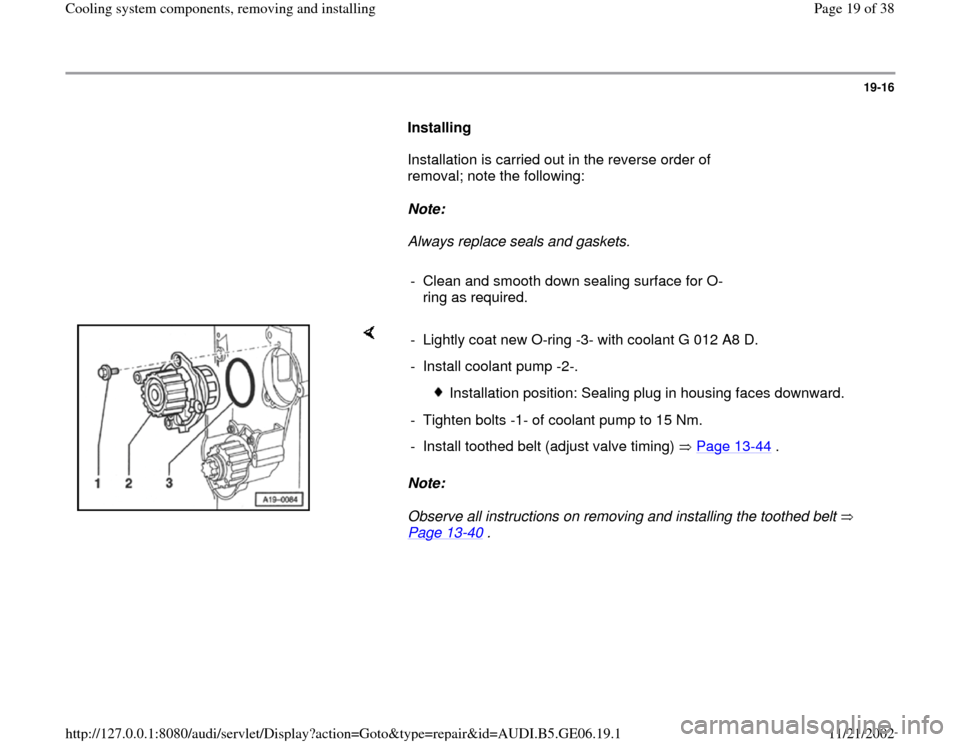
. - Lightly coat new O-ring -3- with coolant G 012 A8 D.
- Install coolant pump -2-.
Installation position: Sealing plug in housing faces downward.
- Tighten bolts -1- of coolant pump to 15 Nm.
- Install toothed belt (adjust valve timing) Page 13
-44
.
Pa
ge 19 of 38 Coolin
g system com
ponents, removin
g and installin
g
11/21/2002 htt
p://127.0.0.1:8080/audi/servlet/Dis
play?action=Goto&t
yp
e=re
pair&id=AUDI.B5.GE06.19.1
Page 20 of 38
19-17
- Install ribbed belt and tensioner for ribbed belt
Page 13
-20
.
- Install viscous fan Page 13
-21
.
- Install lock carrier Page 13
-1 .
- Top up coolant Page 19
-7 .
Tightening torque
Component
Nm
Coolant pump to cylinder block 15
Center section of toothed belt guard to
cylinder block
10
1)
Hose clamps for coolant hoses 2
1) Install with locking fluid D 000 600 A2
Pa
ge 20 of 38 Coolin
g system com
ponents, removin
g and installin
g
11/21/2002 htt
p://127.0.0.1:8080/audi/servlet/Dis
play?action=Goto&t
yp
e=re
pair&id=AUDI.B5.GE06.19.1
Page 21 of 38
19-18
Coolant thermostat, removing and
installing, checking
Removing
- Observe or obtain radio code on vehicles with
coded radio.
- Disconnect Ground strap at battery with ignition
switched off.
- Drain coolant Page 19
-4 .
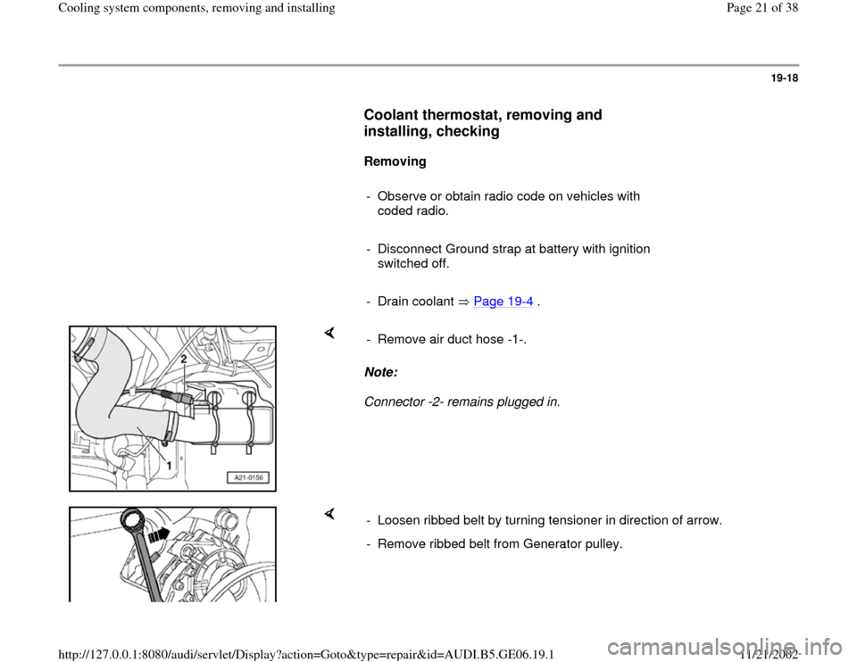
Note:
Connector -2- remains plugged in. - Remove air duct hose -1-.
- Loosen ribbed belt by turning tensioner in direction of arrow.
- Remove ribbed belt from Generator pulley.
Pa
ge 21 of 38 Coolin
g system com
ponents, removin
g and installin
g
11/21/2002 htt
p://127.0.0.1:8080/audi/servlet/Dis
play?action=Goto&t
yp
e=re
pair&id=AUDI.B5.GE06.19.1
Page 23 of 38
19-20
Installing
Installation is carried out in the reverse order of removal; note the
following:
Note:
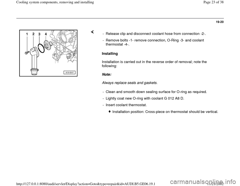
Always replace seals and gaskets. - Release clip and disconnect coolant hose from connection -2-.
- Remove bolts -1- remove connection, O-Ring -3- and coolant
thermostat -4-.
- Clean and smooth down sealing surface for O-ring as required.
- Lightly coat new O-ring with coolant G 012 A8 D.
- Insert coolant thermostat.
Installation position: Cross-piece on thermostat should be vertical.
Pa
ge 23 of 38 Coolin
g system com
ponents, removin
g and installin
g
11/21/2002 htt
p://127.0.0.1:8080/audi/servlet/Dis
play?action=Goto&t
yp
e=re
pair&id=AUDI.B5.GE06.19.1
Page 24 of 38
19-21
- Install viscous fan Page 13
-21
.
- Install ribbed belt and tensioner for ribbed belt
Page 13
-20
.
- After connecting battery, enter anti-theft code for
radio.
Radio operating instructions
- Close windows fully using power window
switches.
- Actuate all power window switches again for at
least one second in the "close" direction to
activate automatic open/close function.
- Set clock to correct time.
- Top up coolant Page 19
-7 .
Pa
ge 24 of 38 Coolin
g system com
ponents, removin
g and installin
g
11/21/2002 htt
p://127.0.0.1:8080/audi/servlet/Dis
play?action=Goto&t
yp
e=re
pair&id=AUDI.B5.GE06.19.1
Page 25 of 38
19-22
Tightening torques
Component
Nm
Connection to cylinder block 15
Support for intake manifold
to intake manifold 20
to bracket 20
Generator at bracket
M8 23
M10 46
Hose clamps for air duct hoses
3.5
Check coolant thermostat
- Heat thermostat in water bath.
Starts to
open
Fully open
Opening
travel
approx. 87 C
approx. 102 C
1)
at least 8 mm
1) cannot be tested
Pa
ge 25 of 38 Coolin
g system com
ponents, removin
g and installin
g
11/21/2002 htt
p://127.0.0.1:8080/audi/servlet/Dis
play?action=Goto&t
yp
e=re
pair&id=AUDI.B5.GE06.19.1
Page 26 of 38
19-23
Lower coolant line, removing and
installing
Special tools and equipment
Removing
VAG 1921
- Drain coolant Page 19
-4 .
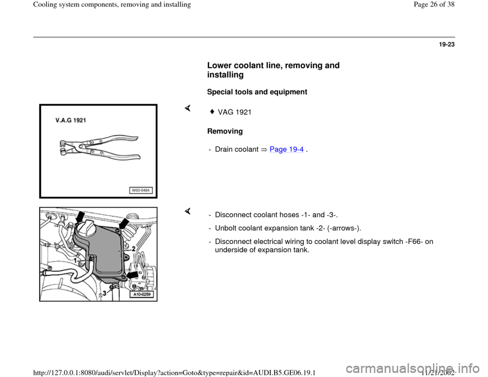
- Disconnect coolant hoses -1- and -3-.
- Unbolt coolant expansion tank -2- (-arrows-).
- Disconnect electrical wiring to coolant level display switch -F66- on
underside of expansion tank.
Pa
ge 26 of 38 Coolin
g system com
ponents, removin
g and installin
g
11/21/2002 htt
p://127.0.0.1:8080/audi/servlet/Dis
play?action=Goto&t
yp
e=re
pair&id=AUDI.B5.GE06.19.1