wiring AUDI A4 1996 B5 / 1.G Brakes ESP DTC Table User Guide
[x] Cancel search | Manufacturer: AUDI, Model Year: 1996, Model line: A4, Model: AUDI A4 1996 B5 / 1.GPages: 96, PDF Size: 0.3 MB
Page 18 of 96
01-372
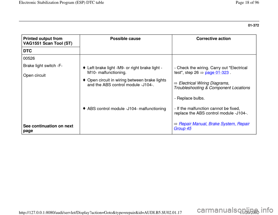
Printed output from
VAG1551 Scan Tool (ST) Possible cause
Corrective action
DTC
00526
Brake light switch -F-
Open circuit
Left brake light -M9- or right brake light -
M10- malfunctioning. Open circuit in wiring between brake lights
and the ABS control module -J104-. Electrical Wiring Diagrams,
Troubleshooting & Component Locations - Check the wiring. Carry out "Electrical
test", step 26 page 01
-323
.
- Replace bulbs.
See continuation on next
page
ABS control module -J104- malfunctioning
Repair Manual, Brake System, Repair
Group 45
- If the malfunction cannot be fixed,
replace the ABS control module -J104-.
Pa
ge 18 of 96 Electronic Stabilization Pro
gram
(ESP
) DTC table
11/20/2002 htt
p://127.0.0.1:8080/audi/servlet/Dis
play?action=Goto&t
yp
e=re
pair&id=AUDI.B5.SU02.01.17
Page 19 of 96
01-373
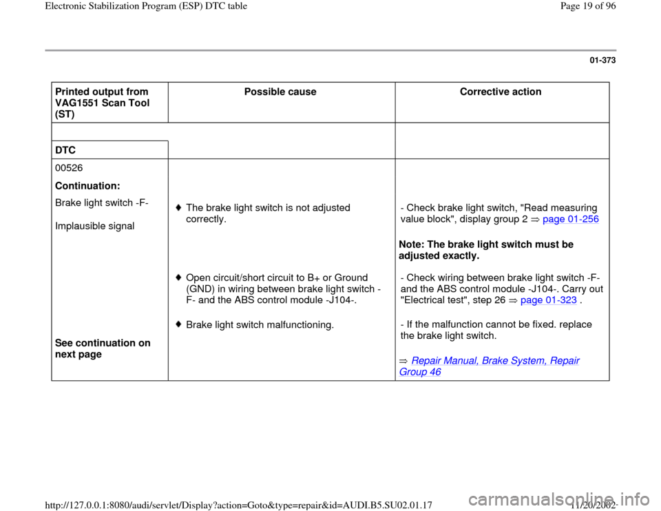
Printed output from
VAG1551 Scan Tool
(ST) Possible cause
Corrective action
DTC
00526
Continuation:
Brake light switch -F-
Implausible signal
The brake light switch is not adjusted
correctly.
Note: The brake light switch must be
adjusted exactly. - Check brake light switch, "Read measuring
value block", display group 2 page 01
-256
Open circuit/short circuit to B+ or Ground
(GND) in wiring between brake light switch -
F- and the ABS control module -J104-. - Check wiring between brake light switch -F-
and the ABS control module -J104-. Carry out
"Electrical test", step 26 page 01
-323
.
See continuation on
next page
Brake light switch malfunctioning.
Repair Manual, Brake System, Repair
Group 46
- If the malfunction cannot be fixed. replace
the brake light switch.
Pa
ge 19 of 96 Electronic Stabilization Pro
gram
(ESP
) DTC table
11/20/2002 htt
p://127.0.0.1:8080/audi/servlet/Dis
play?action=Goto&t
yp
e=re
pair&id=AUDI.B5.SU02.01.17
Page 21 of 96
01-375
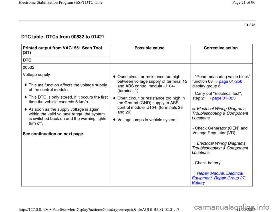
DTC table; DTCs from 00532 to 01421
Printed output from VAG1551 Scan Tool
(ST) Possible cause
Corrective action
DTC
00532
Voltage supply
See continuation on next page
This malfunction affects the voltage supply
of the control module.
This DTC is only stored, if it occurs the first
time the vehicle exceeds 6 km/h.
As soon as the supply voltage is again
within the valid voltage range, the system
is switched back on and the warning lights
turn off.
Open circuit or resistance too high
between voltage supply of terminal 15
and ABS control module -J104-
(terminal 1). Open circuit or resistance too high in
the Ground (GND) supply to ABS
control module -J104- (terminals 28
and 29). Voltage jumps in vehicle system. Electrical Wiring Diagrams,
Troubleshooting & Component
Locations
Electrical Wiring Diagrams,
Troubleshooting & Component
Locations
Repair Manual, Electrical
Equipment, Repair Group 27, Battery
- "Read measuring value block"
function 08 page 01
-256
,
display group 6.
- Carry out "Electrical test",
step 21 page 01
-323
- Check Generator (GEN) and
Voltage Regulator (VR). - Check battery
Pa
ge 21 of 96 Electronic Stabilization Pro
gram
(ESP
) DTC table
11/20/2002 htt
p://127.0.0.1:8080/audi/servlet/Dis
play?action=Goto&t
yp
e=re
pair&id=AUDI.B5.SU02.01.17
Page 22 of 96
01-376
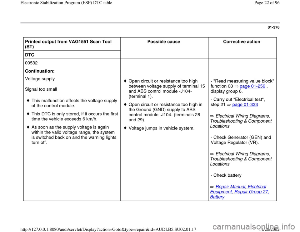
Printed output from VAG1551 Scan Tool
(ST) Possible cause
Corrective action
DTC
00532
Continuation:
Voltage supply
Signal too small
This malfunction affects the voltage supply
of the control module.
This DTC is only stored, if it occurs the first
time the vehicle exceeds 6 km/h.
As soon as the supply voltage is again
within the valid voltage range, the system
is switched back on and the warning lights
turn off.
Open circuit or resistance too high
between voltage supply of terminal 15
and ABS control module -J104-
(terminal 1). Open circuit or resistance too high in
the Ground (GND) supply to ABS
control module -J104- (terminals 28
and 29). Voltage jumps in vehicle system. Electrical Wiring Diagrams,
Troubleshooting & Component
Locations
Electrical Wiring Diagrams,
Troubleshooting & Component
Locations
Repair Manual, Electrical
Equipment, Repair Group 27, Battery
- "Read measuring value block"
function 08 page 01
-256
,
display group 6.
- Carry out "Electrical test",
step 21 page 01
-323
- Check Generator (GEN) and
Voltage Regulator (VR). - Check battery
Pa
ge 22 of 96 Electronic Stabilization Pro
gram
(ESP
) DTC table
11/20/2002 htt
p://127.0.0.1:8080/audi/servlet/Dis
play?action=Goto&t
yp
e=re
pair&id=AUDI.B5.SU02.01.17
Page 28 of 96
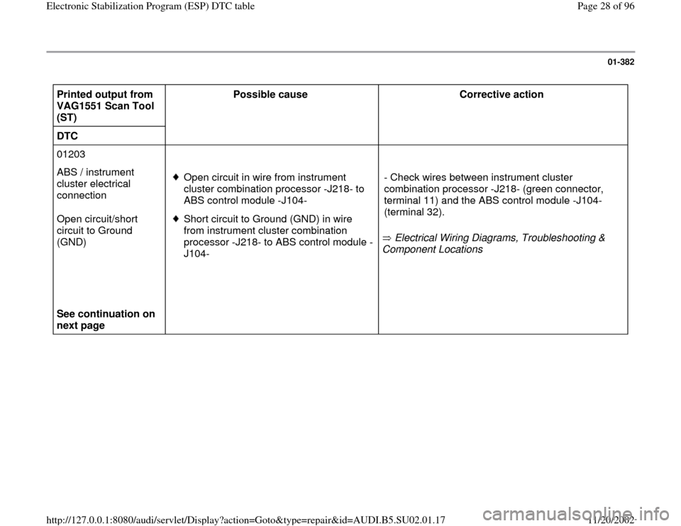
01-382
Printed output from
VAG1551 Scan Tool
(ST) Possible cause
Corrective action
DTC
01203
ABS / instrument
cluster electrical
connection
Open circuit/short
circuit to Ground
(GND)
See continuation on
next page
Open circuit in wire from instrument
cluster combination processor -J218- to
ABS control module -J104-
Short circuit to Ground (GND) in wire
from instrument cluster combination
processor -J218- to ABS control module -
J104- Electrical Wiring Diagrams, Troubleshooting &
Component Locations
- Check wires between instrument cluster
combination processor -J218- (green connector,
terminal 11) and the ABS control module -J104-
(terminal 32).
Pa
ge 28 of 96 Electronic Stabilization Pro
gram
(ESP
) DTC table
11/20/2002 htt
p://127.0.0.1:8080/audi/servlet/Dis
play?action=Goto&t
yp
e=re
pair&id=AUDI.B5.SU02.01.17
Page 29 of 96
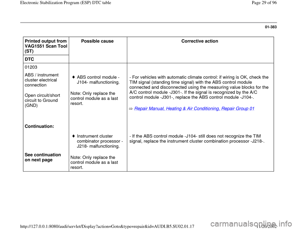
01-383
Printed output from
VAG1551 Scan Tool
(ST) Possible cause
Corrective action
DTC
01203
ABS / instrument
cluster electrical
connection
Open circuit/short
circuit to Ground
(GND)
Continuation: Note: Only replace the
control module as a last
resort.
ABS control module -
J104- malfunctioning.
Repair Manual, Heating & Air Conditioning, Repair Group 01
- For vehicles with automatic climate control: if wiring is OK, check the
TIM signal (standing time signal) with the ABS control module
connected and disconnected using the measuring value blocks for the
A/C control module -J301-. If the signal is recognized by the A/C
control module -J301-, replace the ABS control module -J104-.
See continuation
on next page Note: Only replace the
control module as a last
resort.
Instrument cluster
combinator processor -
J218- malfunctioning. - If the ABS control module -J104- still does not recognize the TIM
signal, replace the instrument cluster combination processor -J218-.
Pa
ge 29 of 96 Electronic Stabilization Pro
gram
(ESP
) DTC table
11/20/2002 htt
p://127.0.0.1:8080/audi/servlet/Dis
play?action=Goto&t
yp
e=re
pair&id=AUDI.B5.SU02.01.17
Page 31 of 96
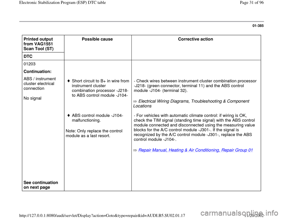
01-385
Printed output
from VAG1551
Scan Tool (ST) Possible cause
Corrective action
DTC
01203
Continuation:
ABS / instrument
cluster electrical
connection
No signal
Short circuit to B+ in wire from
instrument cluster
combination processor -J218-
to ABS control module -J104-
Electrical Wiring Diagrams, Troubleshooting & Component
Locations - Check wires between instrument cluster combination processor
-J218- (green connector, terminal 11) and the ABS control
module -J104- (terminal 32).
See continuation
on next page Note: Only replace the control
module as a last resort.
ABS control module -J104-
malfunctioning.
Repair Manual, Heating & Air Conditioning, Repair Group 01
- For vehicles with automatic climate control: if wiring is OK,
check the TIM signal (standing time signal) with the ABS control
module connected and disconnected using the measuring value
blocks for the A/C control module -J301-. If the signal is
recognized by the A/C control module -J301-, replace the ABS
control module -J104-.
Pa
ge 31 of 96 Electronic Stabilization Pro
gram
(ESP
) DTC table
11/20/2002 htt
p://127.0.0.1:8080/audi/servlet/Dis
play?action=Goto&t
yp
e=re
pair&id=AUDI.B5.SU02.01.17
Page 34 of 96
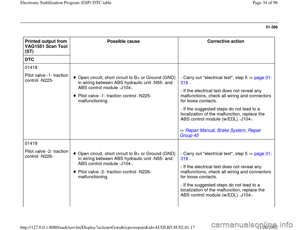
01-388
Printed output from
VAG1551 Scan Tool
(ST) Possible cause
Corrective action
DTC
01418
Pilot valve -1- traction
control -N225-
Open circuit, short circuit to B+ or Ground (GND)
in wiring between ABS hydraulic unit -N55- and
ABS control module -J104-.
Pilot valve -1- traction control -N225-
malfunctioning.
Repair Manual, Brake System, Repair
Group 45
- Carry out "electrical test", step 5 page 01
-
318
.
- If the electrical test does not reveal any
malfunctions, check all wiring and connectors
for loose contacts.
- If the suggested steps do not lead to a
localization of the malfunction, replace the
ABS control module (w/EDL) -J104-.
01419
Pilot valve -2- traction
control -N226-
Open circuit, short circuit to B+ or Ground (GND)
in wiring between ABS hydraulic unit -N55- and
ABS control module -J104-.
Pilot valve -2- traction control -N226-
malfunctioning. - Carry out "electrical test", step 5 page 01
-
318
.
- If the electrical test does not reveal any
malfunctions, check all wiring and connectors
for loose contacts.
- If the suggested steps do not lead to a
localization of the malfunction, replace the
ABS control module (w/EDL) -J104-.
Pa
ge 34 of 96 Electronic Stabilization Pro
gram
(ESP
) DTC table
11/20/2002 htt
p://127.0.0.1:8080/audi/servlet/Dis
play?action=Goto&t
yp
e=re
pair&id=AUDI.B5.SU02.01.17
Page 36 of 96
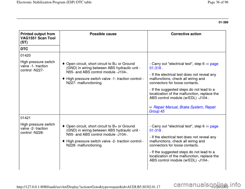
01-389
Printed output from
VAG1551 Scan Tool
(ST) Possible cause
Corrective action
DTC
01420
High pressure switch
valve -1- traction
control -N227-
Open circuit, short circuit to B+ or Ground
(GND) in wiring between ABS hydraulic unit -
N55- and ABS control module -J104-.
High pressure switch valve -1- traction control -
N227- malfunctioning.
Repair Manual, Brake System, Repair
Group 45
- Carry out "electrical test", step 6 page
01
-318
.
- If the electrical test does not reveal any
malfunctions, check all wiring and
connectors for loose contacts.
- If the suggested steps do not lead to a
localization of the malfunction, replace the
ABS control module (w/EDL) -J104-.
01421
High pressure switch
valve -2- traction
control -N228-
Open circuit, short circuit to B+ or Ground
(GND) in wiring between ABS hydraulic unit -
N55- and ABS control module -J104-.
High pressure switch valve -2- traction control -
N228- malfunctioning. - Carry out "electrical test", step 6 page
01
-318
.
- If the electrical test does not reveal any
malfunctions, check all wiring and
connectors for loose contacts.
- If the suggested steps do not lead to a
localization of the malfunction, replace the
ABS control module (w/EDL) -J104-.
Pa
ge 36 of 96 Electronic Stabilization Pro
gram
(ESP
) DTC table
11/20/2002 htt
p://127.0.0.1:8080/audi/servlet/Dis
play?action=Goto&t
yp
e=re
pair&id=AUDI.B5.SU02.01.17
Page 38 of 96
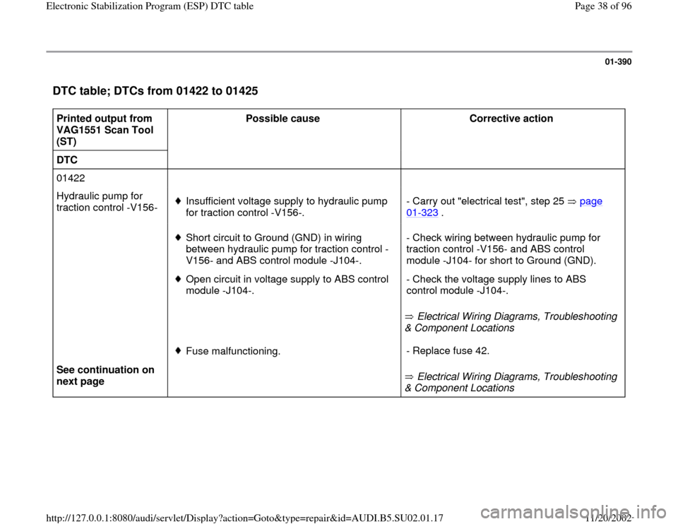
01-390
DTC table; DTCs from 01422 to 01425
Printed output from
VAG1551 Scan Tool
(ST) Possible cause
Corrective action
DTC
01422
Hydraulic pump for
traction control -V156-
Insufficient voltage supply to hydraulic pump
for traction control -V156-. - Carry out "electrical test", step 25 page
01
-323
.
Short circuit to Ground (GND) in wiring
between hydraulic pump for traction control -
V156- and ABS control module -J104-.
Open circuit in voltage supply to ABS control
module -J104-.
Electrical Wiring Diagrams, Troubleshooting
& Component Locations - Check wiring between hydraulic pump for
traction control -V156- and ABS control
module -J104- for short to Ground (GND).
- Check the voltage supply lines to ABS
control module -J104-.
See continuation on
next page
Fuse malfunctioning.
Electrical Wiring Diagrams, Troubleshooting
& Component Locations - Replace fuse 42.
Pa
ge 38 of 96 Electronic Stabilization Pro
gram
(ESP
) DTC table
11/20/2002 htt
p://127.0.0.1:8080/audi/servlet/Dis
play?action=Goto&t
yp
e=re
pair&id=AUDI.B5.SU02.01.17