check engine AUDI A4 1996 B5 / 1.G EVAP Workshop Manual
[x] Cancel search | Manufacturer: AUDI, Model Year: 1996, Model line: A4, Model: AUDI A4 1996 B5 / 1.GPages: 65, PDF Size: 0.77 MB
Page 2 of 65
20-131
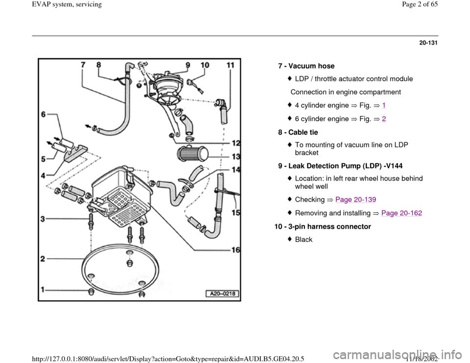
7 -
Vacuum hose
LDP / throttle actuator control module
Connection in engine compartment4 cylinder engine Fig. 16 cylinder engine Fig. 2
8 -
Cable tie
To mounting of vacuum line on LDP
bracket
9 -
Leak Detection Pump (LDP) -V144 Location: in left rear wheel house behind
wheel well Checking Page 20
-139
Removing and installing Page 20
-162
10 -
3-pin harness connector
Black
Pa
ge 2 of 65 EVAP s
ystem, servicin
g
11/18/2002 htt
p://127.0.0.1:8080/audi/servlet/Dis
play?action=Goto&t
yp
e=re
pair&id=AUDI.B5.GE04.20.5
Page 14 of 65
20-140
Checking LDP via Read Measuring Value
Block (vehicles with mechanical throttle
control)
Note:
Always replace O-rings, sealing rings and
gaskets.
Radiator fan must not come on during the
test!
Troubleshooting requirements
DTC memory checked and no DTCs stored
All electrical consumers switched OFF
A/C switched OFF
Intake Air Temperature lower than 90 C
Display group 004, channel 4.
Engine Coolant Temperature less than 95
C Display group 004, channel 3.
Throttle angle less than 10 % Display
Pa
ge 14 of 65 EVAP s
ystem, servicin
g
11/18/2002 htt
p://127.0.0.1:8080/audi/servlet/Dis
play?action=Goto&t
yp
e=re
pair&id=AUDI.B5.GE04.20.5
Page 17 of 65
20-142
- Press 0 and 1 buttons to select Address word
01: "Engine electronics".
- Press Q button to enter input.
-
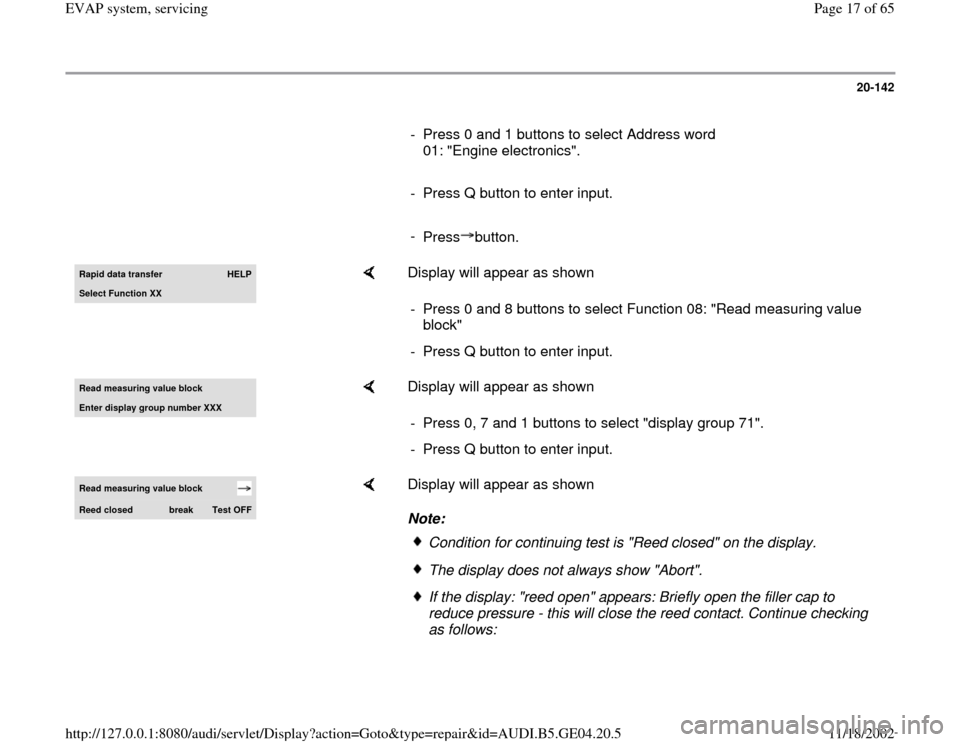
Press button.Rapid data transfer
HELP
Select Function XX
Display will appear as shown
- Press 0 and 8 buttons to select Function 08: "Read measuring value
block"
- Press Q button to enter input.
Read measurin
g value block
Enter displa
y group number XXX
Display will appear as shown
- Press 0, 7 and 1 buttons to select "display group 71".
- Press Q button to enter input.
Read measuring value block Reed closed
break
Test OFF
Display will appear as shown
Note:
Condition for continuing test is "Reed closed" on the display.The display does not always show "Abort".If the display: "reed open" appears: Briefly open the filler cap to
reduce pressure - this will close the reed contact. Continue checking
as follows:
Pa
ge 17 of 65 EVAP s
ystem, servicin
g
11/18/2002 htt
p://127.0.0.1:8080/audi/servlet/Dis
play?action=Goto&t
yp
e=re
pair&id=AUDI.B5.GE04.20.5
Page 26 of 65
20-151
Checking voltage supply (all vehicles)
Note:
Voltage supply to the LDP is via the fuel pump
relay.
Test condition:
Fuse for LDP is OK
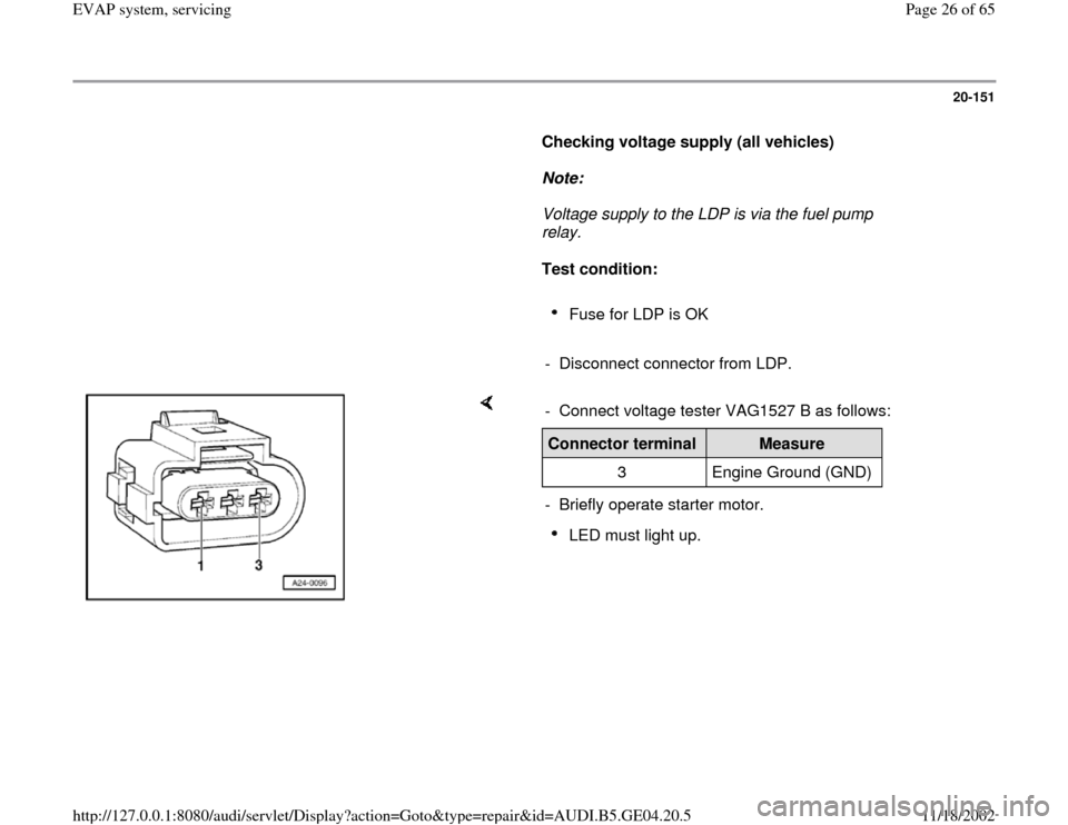
- Disconnect connector from LDP.
- Connect voltage tester VAG1527 B as follows:Connector terminal
Measure
3 Engine Ground (GND)
- Briefly operate starter motor.
LED must light up.
Pa
ge 26 of 65 EVAP s
ystem, servicin
g
11/18/2002 htt
p://127.0.0.1:8080/audi/servlet/Dis
play?action=Goto&t
yp
e=re
pair&id=AUDI.B5.GE04.20.5
Page 28 of 65
20-153
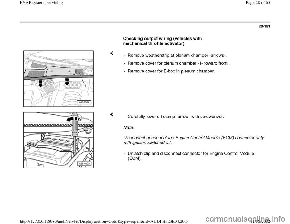
Checking output wiring (vehicles with
mechanical throttle activator)
- Remove weatherstrip at plenum chamber -arrows-.
- Remove cover for plenum chamber -1- toward front.
- Remove cover for E-box in plenum chamber.
Note:
Disconnect or connect the Engine Control Module (ECM) connector only
with ignition switched off. - Carefully lever off clamp -arrow- with screwdriver.
- Unlatch clip and disconnect connector for Engine Control Module
(ECM).
Pa
ge 28 of 65 EVAP s
ystem, servicin
g
11/18/2002 htt
p://127.0.0.1:8080/audi/servlet/Dis
play?action=Goto&t
yp
e=re
pair&id=AUDI.B5.GE04.20.5
Page 56 of 65
20-176
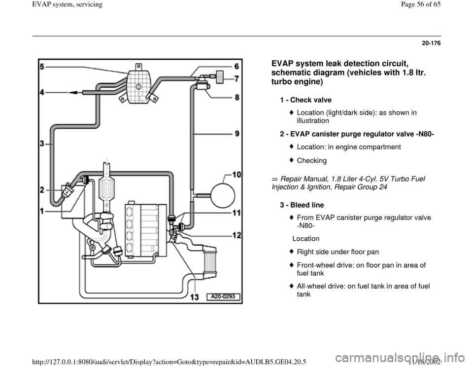
EVAP system leak detection circuit,
schematic diagram (vehicles with 1.8 ltr.
turbo engine)
Repair Manual, 1.8 Liter 4-Cyl. 5V Turbo Fuel
Injection & Ignition, Repair Group 24 1 -
Check valve
Location (light/dark side): as shown in
illustration
2 -
EVAP canister purge regulator valve -N80-Location: in engine compartmentChecking
3 -
Bleed line
From EVAP canister purge regulator valve
-N80-
LocationRight side under floor panFront-wheel drive: on floor pan in area of
fuel tank All-wheel drive: on fuel tank in area of fuel
tank
Pa
ge 56 of 65 EVAP s
ystem, servicin
g
11/18/2002 htt
p://127.0.0.1:8080/audi/servlet/Dis
play?action=Goto&t
yp
e=re
pair&id=AUDI.B5.GE04.20.5
Page 60 of 65
20-180
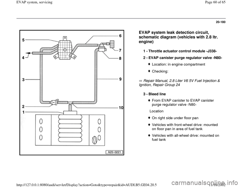
EVAP system leak detection circuit,
schematic diagram (vehicles with 2.8 ltr.
engine)
Repair Manual, 2.8 Liter V6 5V Fuel Injection &
Ignition, Repair Group 24 1 -
Throttle actuator control module -J338-
2 -
EVAP canister purge regulator valve -N80-Location: in engine compartmentChecking:
3 -
Bleed line
From EVAP canister to EVAP canister
purge regulator valve -N80-
LocationOn right side under floor panVehicles with front-wheel drive: mounted
on floor pan in area of fuel tank Vehicles with all-wheel drive: mounted on
fuel tank
Pa
ge 60 of 65 EVAP s
ystem, servicin
g
11/18/2002 htt
p://127.0.0.1:8080/audi/servlet/Dis
play?action=Goto&t
yp
e=re
pair&id=AUDI.B5.GE04.20.5
Page 63 of 65
20-183
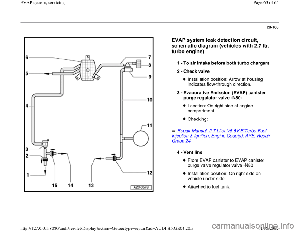
EVAP system leak detection circuit,
schematic diagram (vehicles with 2.7 ltr.
turbo engine)
Repair Manual, 2.7 Liter V6 5V BiTurbo Fuel
Injection & Ignition, Engine Code(s): APB, Repair Group 24
1 -
To air intake before both turbo chargers
2 -
Check valve Installation position: Arrow at housing
indicates flow-through direction.
3 -
Evaporative Emission (EVAP) canister
purge regulator valve -N80- Location: On right side of engine
compartment Checking:
4 -
Vent line
From EVAP canister to EVAP canister
purge valve regulator valve -N80 Installation position: On right side on
vehicle under-side. Attached to fuel tank.
Pa
ge 63 of 65 EVAP s
ystem, servicin
g
11/18/2002 htt
p://127.0.0.1:8080/audi/servlet/Dis
play?action=Goto&t
yp
e=re
pair&id=AUDI.B5.GE04.20.5