torque AUDI A4 1997 B5 / 1.G 01A Transmission Pinion Shaft Remove And Install Workshop Manual
[x] Cancel search | Manufacturer: AUDI, Model Year: 1997, Model line: A4, Model: AUDI A4 1997 B5 / 1.GPages: 13, PDF Size: 0.3 MB
Page 3 of 13
39-135
3062 thrust pad
3138 drift
3253 wheel bearing assembly set with 3253/3
and 3253/4
3304 bracket
VAG1383A engine/transmission support
VAG1359/2 universal mount
Kukko 17/2 separating tool
Kukko 21/7 extractor
Kukko 22/2 support
Torque gauge 0-600 Ncm (0-53 in. lb)
32 mm socket
Pa
ge 3 of 13 Pinion shaft, removin
g, installin
g and servicin
g
11/20/2002 htt
p://127.0.0.1:8080/audi/servlet/Dis
play?action=Goto&t
yp
e=re
pair&id=AUDI.B5.TM02.39.16
Page 4 of 13
39-136
Notes:
Observe general repair instructions Page 00
-
14
.
With the final drive installed, remove the drive
flange housing from the rear final drive Page 39
-86
.
With the final drive removed, remove the drive
flange housing from the rear final drive Page 39
-119
.
Always replace both tapered roller bearings
together as a set. If possible, use same
manufacturer.
Do not oil new tapered roller bearings for the
friction torque measurement. The bearings are
already factory treated with a special oil.
Remove differential Page 39
-114
.
Adjustments are required when replacing
components marked with "1)" List of
adjustments, Page 39
-149
.
Pa
ge 4 of 13 Pinion shaft, removin
g, installin
g and servicin
g
11/20/2002 htt
p://127.0.0.1:8080/audi/servlet/Dis
play?action=Goto&t
yp
e=re
pair&id=AUDI.B5.TM02.39.16
Page 5 of 13
39-137
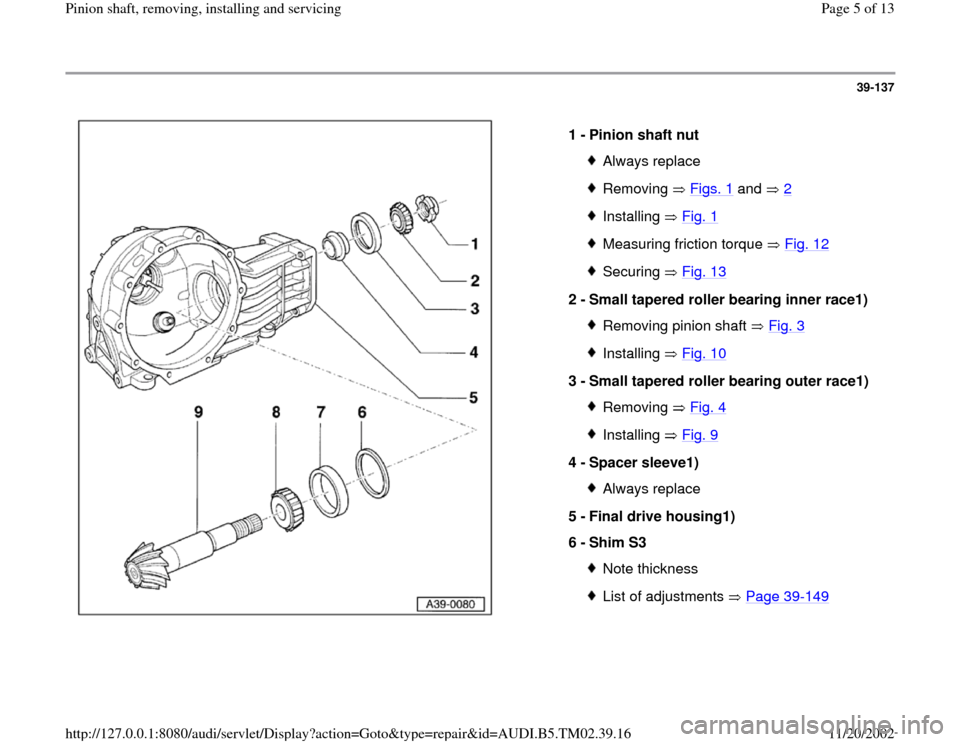
1 -
Pinion shaft nut
Always replaceRemoving Figs. 1
and 2
Installing Fig. 1Measuring friction torque Fig. 12Securing Fig. 13
2 -
Small tapered roller bearing inner race1)
Removing pinion shaft Fig. 3Installing Fig. 10
3 -
Small tapered roller bearing outer race1)
Removing Fig. 4Installing Fig. 9
4 -
Spacer sleeve1)
Always replace
5 -
Final drive housing1)
6 -
Shim S3 Note thicknessList of adjustments Page 39
-149
Pa
ge 5 of 13 Pinion shaft, removin
g, installin
g and servicin
g
11/20/2002 htt
p://127.0.0.1:8080/audi/servlet/Dis
play?action=Goto&t
yp
e=re
pair&id=AUDI.B5.TM02.39.16
Page 12 of 13
39-144
Note:
If the specified friction torque is exceeded, the spacer sleeve must be
replaced and the adjustment repeated. A spacer sleeve that has been
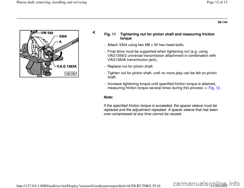
over-compressed at any time cannot be reused. Fig. 11 Tightening nut for pinion shaft and measuring friction
torque
- Attach 3304 using two M8 x 30 hex-head bolts.
- Final drive must be supported when tightening nut (e.g. using
VAG1359/2 universal transmission attachment in combination with
VAG1383A transmission jack).
- Replace nut for pinion shaft.
- Tighten nut for pinion shaft, until no more play can be felt on pinion
shaft.
- Increase tightening torque until specified friction torque is attained,
measuring friction torque several times during this process Fig. 12
.
Pa
ge 12 of 13 Pinion shaft, removin
g, installin
g and servicin
g
11/20/2002 htt
p://127.0.0.1:8080/audi/servlet/Dis
play?action=Goto&t
yp
e=re
pair&id=AUDI.B5.TM02.39.16
Page 13 of 13
39-145
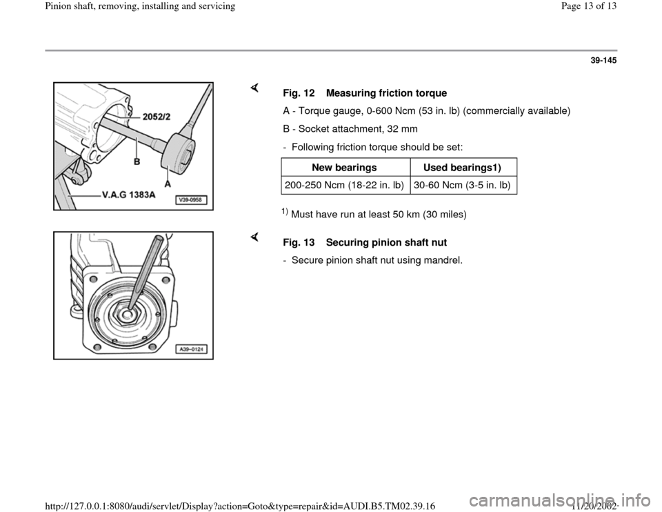
1) Must have run at least 50 km (30 miles) Fig. 12 Measuring friction torque
A - Torque gauge, 0-600 Ncm (53 in. lb) (commercially available)
B - Socket attachment, 32 mm
- Following friction torque should be set:
New bearings
Used bearings1)
200-250 Ncm (18-22 in. lb) 30-60 Ncm (3-5 in. lb)
Fig. 13 Securing pinion shaft nut
- Secure pinion shaft nut using mandrel.
Pa
ge 13 of 13 Pinion shaft, removin
g, installin
g and servicin
g
11/20/2002 htt
p://127.0.0.1:8080/audi/servlet/Dis
play?action=Goto&t
yp
e=re
pair&id=AUDI.B5.TM02.39.16