instrument cluster AUDI A4 1997 B5 / 1.G AC System Electrical Testing Workshop Manual
[x] Cancel search | Manufacturer: AUDI, Model Year: 1997, Model line: A4, Model: AUDI A4 1997 B5 / 1.GPages: 47, PDF Size: 0.16 MB
Page 22 of 47
01-132
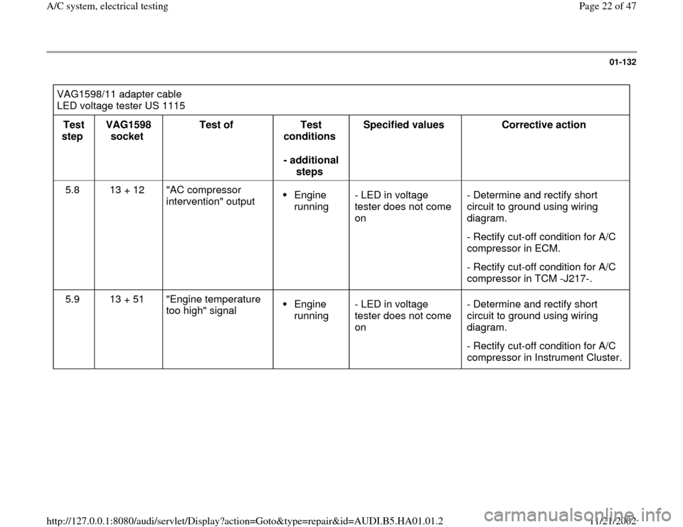
VAG1598/11 adapter cable
LED voltage tester US 1115
Test
step VAG1598
socket Test of
Test
conditions
- additional
steps Specified values
Corrective action
5.8 13 + 12 "AC compressor
intervention" output
Engine
running - LED in voltage
tester does not come
on - Determine and rectify short
circuit to ground using wiring
diagram.
- Rectify cut-off condition for A/C
compressor in ECM.
- Rectify cut-off condition for A/C
compressor in TCM -J217-.
5.9 13 + 51 "Engine temperature
too high" signal Engine
running - LED in voltage
tester does not come
on - Determine and rectify short
circuit to ground using wiring
diagram.
- Rectify cut-off condition for A/C
compressor in Instrument Cluster.
Pa
ge 22 of 47 A/C s
ystem, electrical testin
g
11/21/2002 htt
p://127.0.0.1:8080/audi/servlet/Dis
play?action=Goto&t
yp
e=re
pair&id=AUDI.B5.HA01.01.2
Page 28 of 47
01-137
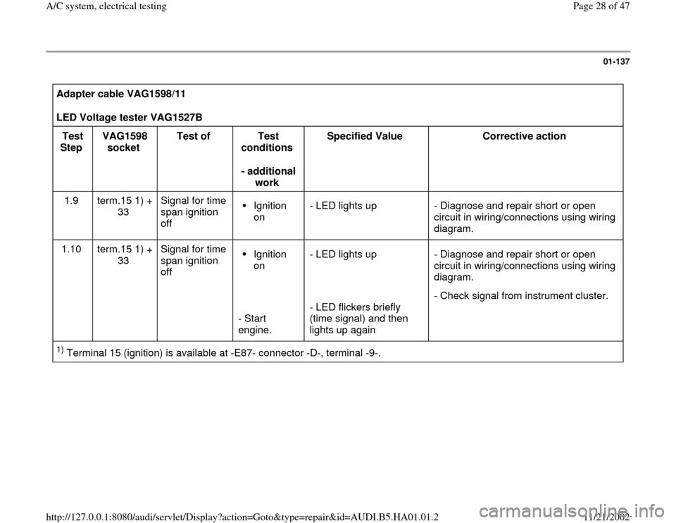
Adapter cable VAG1598/11
LED Voltage tester VAG1527B
Test
Step VAG1598
socket Test of
Test
conditions
- additional
work Specified Value
Corrective action
1.9 term.15 1) +
33 Signal for time
span ignition
off
Ignition
on - LED lights up - Diagnose and repair short or open
circuit in wiring/connections using wiring
diagram.
1.10 term.15 1) +
33 Signal for time
span ignition
off Ignition
on
- Start
engine. - LED lights up
- LED flickers briefly
(time signal) and then
lights up again - Diagnose and repair short or open
circuit in wiring/connections using wiring
diagram.
- Check signal from instrument cluster.
1) Terminal 15 (ignition) is available at -E87- connector -D-, terminal -9-.
Pa
ge 28 of 47 A/C s
ystem, electrical testin
g
11/21/2002 htt
p://127.0.0.1:8080/audi/servlet/Dis
play?action=Goto&t
yp
e=re
pair&id=AUDI.B5.HA01.01.2
Page 34 of 47
01-142
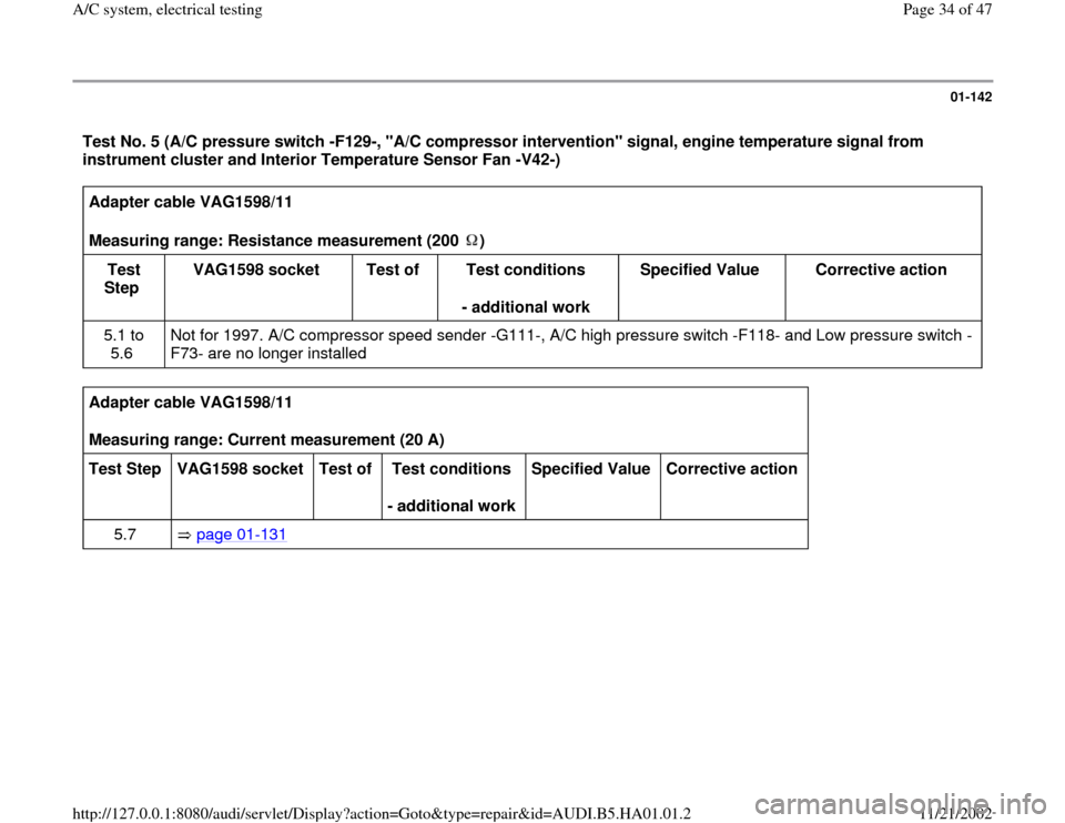
Test No. 5 (A/C pressure switch -F129-, "A/C compressor intervention" signal, engine temperature signal from
instrument cluster and Interior Temperature Sensor Fan -V42-) Adapter cable VAG1598/11
Measuring range: Resistance measurement (200 )
Test
Step VAG1598 socket
Test of
Test conditions
- additional work Specified Value
Corrective action
5.1 to
5.6 Not for 1997. A/C compressor speed sender -G111-, A/C high pressure switch -F118- and Low pressure switch -
F73- are no longer installed
Adapter cable VAG1598/11
Measuring range: Current measurement (20 A)
Test Step
VAG1598 socket
Test of
Test conditions
- additional work Specified Value
Corrective action
5.7 page 01
-131
Pa
ge 34 of 47 A/C s
ystem, electrical testin
g
11/21/2002 htt
p://127.0.0.1:8080/audi/servlet/Dis
play?action=Goto&t
yp
e=re
pair&id=AUDI.B5.HA01.01.2
Page 35 of 47

01-143
A/C control head -E87- connected to test box with adapter cable VAG1598/11
LED Voltage tester VAG1527B
Test
Step VAG1598
socket Test of
Test conditions
- additional work Specified
Value Corrective action
5.8 14 + 12 "A/C compressor
intervention"
output.
Engine
running. A/C
compressor
off
- Switch on A/C
compressor - LED lights
up
- LED lights
up slightly
dimmer. - Diagnose and repair open or short circuit in
wiring/connections using wiring diagram.
- Diagnose and eliminate A/C compressor
cut-off condition(s) from Engine Control
Module (ECM) or Transmission Control
Module (TCM)
- Diagnose and repair short circuit to ground
in wiring/connections using wiring diagram.
5.9 Ground
and
51 "Engine
temperature too
high" signal. Engine
running. - LED lights
up. - Diagnose and repair short circuit to ground
in wiring/connections using wiring diagram.
- Diagnose and eliminate A/C compressor
cut-off condition from Instrument cluster
Pa
ge 35 of 47 A/C s
ystem, electrical testin
g
11/21/2002 htt
p://127.0.0.1:8080/audi/servlet/Dis
play?action=Goto&t
yp
e=re
pair&id=AUDI.B5.HA01.01.2
Page 42 of 47
01-149
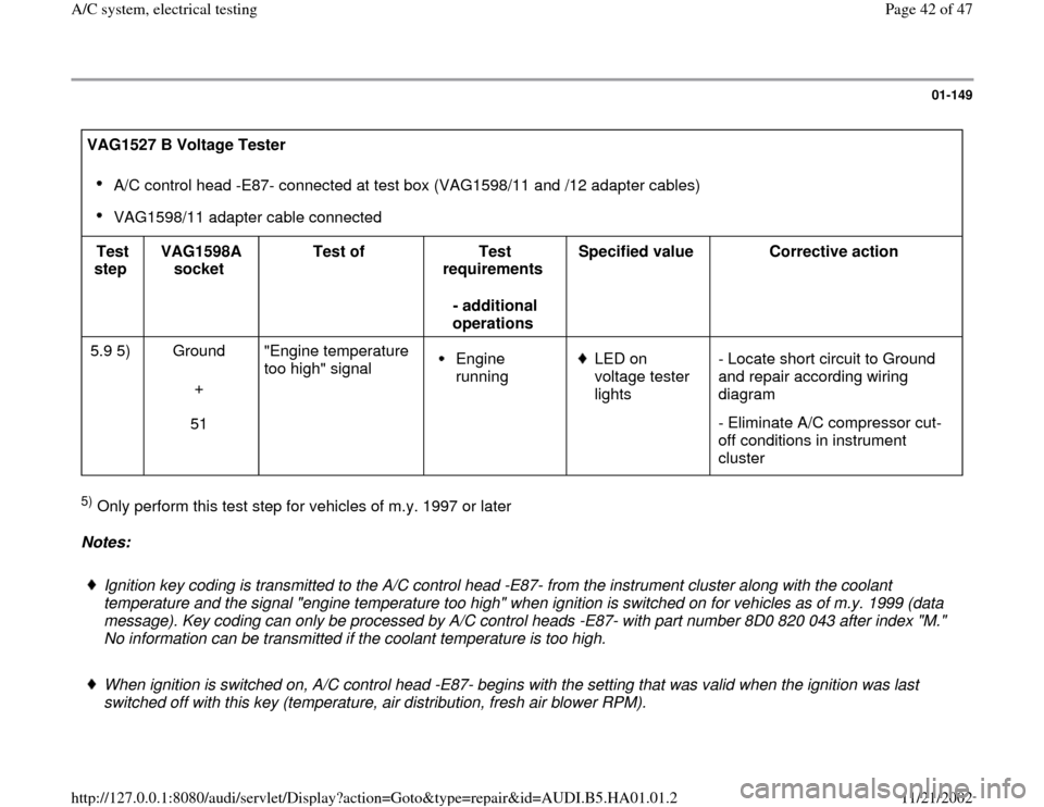
VAG1527 B Voltage Tester
A/C control head -E87- connected at test box (VAG1598/11 and /12 adapter cables)
VAG1598/11 adapter cable connected
Test
step VAG1598A
socket Test of
Test
requirements
- additional
operations Specified value
Corrective action
5.9 5) Ground
+
51 "Engine temperature
too high" signal
Engine
running
LED on
voltage tester
lights - Locate short circuit to Ground
and repair according wiring
diagram
- Eliminate A/C compressor cut-
off conditions in instrument
cluster
5) Only perform this test step for vehicles of m.y. 1997 or later
Notes:
Ignition key coding is transmitted to the A/C control head -E87- from the instrument cluster along with the coolant
temperature and the signal "engine temperature too high" when ignition is switched on for vehicles as of m.y. 1999 (data
message). Key coding can only be processed by A/C control heads -E87- with part number 8D0 820 043 after index "M."
No information can be transmitted if the coolant temperature is too high.
When ignition is switched on, A/C control head -E87- begins with the setting that was valid when the ignition was last
switched off with this key (temperature, air distribution, fresh air blower RPM).
Pa
ge 42 of 47 A/C s
ystem, electrical testin
g
11/21/2002 htt
p://127.0.0.1:8080/audi/servlet/Dis
play?action=Goto&t
yp
e=re
pair&id=AUDI.B5.HA01.01.2
Page 43 of 47

The signal from instrument cluster (data message) cannot be checked with tools available.
Repair Manual, "Electrical Equipment," Repair Group 90, instrument cluster, repairing.
Pa
ge 43 of 47 A/C s
ystem, electrical testin
g
11/21/2002 htt
p://127.0.0.1:8080/audi/servlet/Dis
play?action=Goto&t
yp
e=re
pair&id=AUDI.B5.HA01.01.2
Page 44 of 47
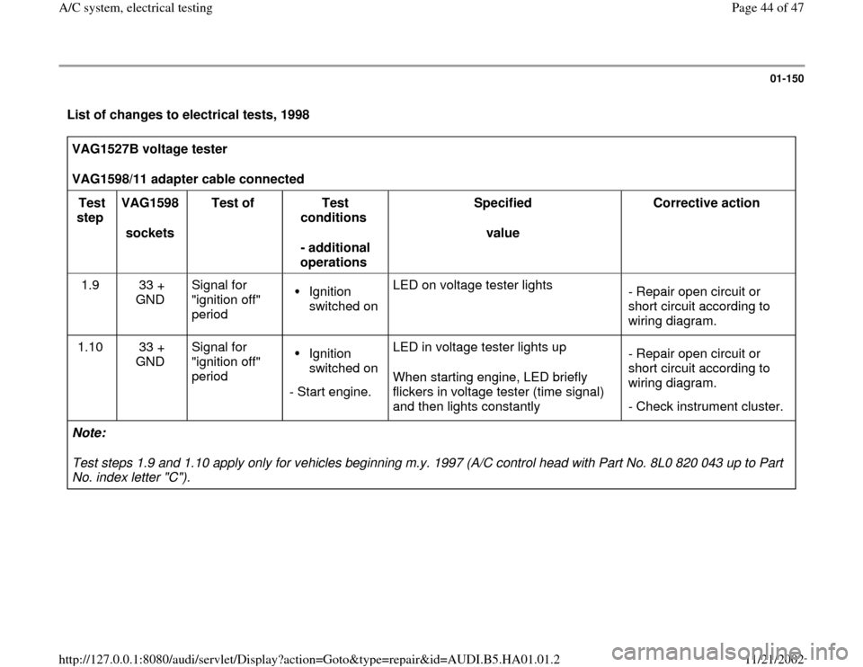
01-150
List of changes to electrical tests, 1998 VAG1527B voltage tester
VAG1598/11 adapter cable connected
Test
step VAG1598
sockets Test of
Test
conditions
- additional
operations Specified
value Corrective action
1.9 33 +
GND Signal for
"ignition off"
period
Ignition
switched on LED on voltage tester lights
- Repair open circuit or
short circuit according to
wiring diagram.
1.10 33 +
GND Signal for
"ignition off"
period Ignition
switched on
- Start engine.LED in voltage tester lights up
When starting engine, LED briefly
flickers in voltage tester (time signal)
and then lights constantly - Repair open circuit or
short circuit according to
wiring diagram.
- Check instrument cluster.
Note:
Test steps 1.9 and 1.10 apply only for vehicles beginning m.y. 1997 (A/C control head with Part No. 8L0 820 043 up to Part
No. index letter "C").
Pa
ge 44 of 47 A/C s
ystem, electrical testin
g
11/21/2002 htt
p://127.0.0.1:8080/audi/servlet/Dis
play?action=Goto&t
yp
e=re
pair&id=AUDI.B5.HA01.01.2
Page 46 of 47

01-152
Voltage test - switch multimeter to 20V measuring range
VAG1598/11 adapter cable connected
Test
step VAG1598
sockets Test of
Test conditions
- additional
operations Specified
value Corrective action
1.13 45 +
GND Terminal 58d on -
E87-
Ignition switched
on Parking light
switched on 0 to12 V
- Repair open circuit or short circuit
according to wiring diagram.
1.14 45 +
GND Terminal 58d on -
E87- Ignition switched
on Parking light
switched off 0 to 12 V
- Repair open circuit or short circuit
according to wiring diagram.
Notes:
Test steps 1.11 - 1.14 apply for vehicles beginning m.y. 1998 (A/C control head with Part No 8L0 820 043 from Part No.
index letter "D").
The Ground connection can be made via connector D, terminals 14 and 15 (for example).
The voltage to terminal 58d is created as a square-wave signal from the instrument cluster. The brightness of the display
on A/C control head -E87- is determined by the period of activation. The multimeter will indicate the average value.
Pa
ge 46 of 47 A/C s
ystem, electrical testin
g
11/21/2002 htt
p://127.0.0.1:8080/audi/servlet/Dis
play?action=Goto&t
yp
e=re
pair&id=AUDI.B5.HA01.01.2
Page 47 of 47

The period of activation for terminal 58d is dependent on the setting of the illumination dimmer control and on the
brightness level detected by the photo sensor in the instrument cluster.
Pa
ge 47 of 47 A/C s
ystem, electrical testin
g
11/21/2002 htt
p://127.0.0.1:8080/audi/servlet/Dis
play?action=Goto&t
yp
e=re
pair&id=AUDI.B5.HA01.01.2